A mixer for concrete mixing plant
Technical Field
The utility model belongs to the technical field of concrete mixing equipment technique and specifically relates to just a mixer for concrete mixing plant.
Background
Brief introduction: the production of concrete, which is called concrete for short, dates back to the ancient times, and the used cementing materials are clay, lime, gypsum, volcanic ash and the like. The concrete is prepared by mixing and stirring a plurality of raw materials according to a certain proportion, and different raw materials and different proportions can generate great influence on the property of the concrete. The concrete mixing plant equipment is a building material manufacturing equipment consisting of five composition systems of a mixing host machine, a material weighing system, a material conveying system, a material storage system and a control system and other accessory facilities, and the main working principle of the concrete mixing plant equipment is that cement is used as a cementing material, raw materials such as sand stone, lime, coal cinder and the like are mixed and stirred, and finally, concrete is manufactured. A multipurpose horizontal mixer is used in a concrete mixing plant, a spiral mixing paddle is mostly adopted in the horizontal mixer in the prior art, concrete on the wall of a mixing tank cannot be scraped out, and the filling volume of the concrete is easy to reduce for a long time and is difficult to clean;
quote: for example, a single-shaft horizontal forced concrete mixer with publication number CN205889526U can effectively scrape out the concrete on the side wall of the mixing tank by arranging L-shaped mixing rollers, but has poor mixing and scraping effects on the concrete at the two ends of the mixing tank, and the mixing roller has small volume and poor mixing effect on the concrete;
the novel conception is as follows: a mixer for concrete mixing plant is designed, the effect of stirring and scraping concrete inside and at two ends of a mixing tank is improved, and the efficiency of stirring inside concrete is improved to be very necessary.
SUMMERY OF THE UTILITY MODEL
For solving the inside stirring of above-mentioned concrete mixing tank and scraping the not good problem of effect, the utility model provides a mixer for concrete mixing plant.
The utility model provides a technical scheme that its technical problem adopted is: the utility model provides a mixer for concrete mixing plant, includes stirring part, agitator tank and support part, the stirring part set up in the agitator tank, the agitator tank set up in support part, the stirring part include (mixing) shaft, stirring vane and stirring end piece set up on the (mixing) shaft, stirring vane include the stirring pillar and stir wide piece, the wide piece of stirring set up on the stirring pillar, the stirring pillar set up on the (mixing) shaft.
As optimization, the stirring pillar set up perpendicularly on the (mixing) shaft, stirring pillar end be equipped with the scraper blade, the (mixing) shaft on be equipped with a plurality of stirring pillar, the even symmetry of a plurality of stirring pillar set up on the (mixing) shaft, the wide piece of stirring be equipped with a plurality of, the wide piece interval of a plurality of stirring set up on the stirring pillar.
Preferably, the stirring end pieces are triangular, the number of the stirring end pieces is two, and the two stirring end pieces are symmetrically arranged at two ends of the stirring shaft.
Preferably, two ends of the stirring shaft are provided with two stirring motors.
Preferably, the support part comprises a shaft support and a motor support, the shaft support is arranged on the stirring shaft, and the motor support is arranged below the motor.
The whole beneficial effect of this scheme is: the utility model provides a mixer for concrete mixing plant, is through setting up stirring end piece on the (mixing) shaft in the agitator tank, not only can improve the stirring effect to agitator tank both ends concrete, also can carry out effectual scraping to the concrete on the lateral wall of agitator tank both ends simultaneously, sets up stirring vane and stirring width piece on the (mixing) shaft, can improve equipment's stirring efficiency greatly when scraping through the concrete to on the agitator tank lateral wall, shortens the churning time, improves the concrete quality.
Drawings
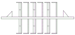
Fig. 1 is a schematic axial view of the present invention.
Figure 2 is the structure schematic diagram of the stirring component of the utility model.
Fig. 3 is a schematic view of the stirring component of the present invention.
The stirring device comprises a stirring component 1, a stirring tank 2, a stirring tank 3, a support part 4, a stirring shaft 5, a stirring blade 6, a stirring end piece 7, a stirring support column 8, a stirring wide piece 9, a scraping plate 10, a stirring motor 11, a shaft support 12 and a motor support.
Detailed Description
In order to make the objects, technical solutions and advantages of the embodiments of the present invention clearer, the embodiments of the present invention will be clearly and completely described below with reference to the accompanying drawings in the embodiments of the present invention, and it is obvious that the described embodiments are some, but not all, embodiments of the present invention. The components of embodiments of the present invention, as generally described and illustrated in the figures herein, may be arranged and designed in a wide variety of different configurations. Thus, the following detailed description of the embodiments of the present invention, presented in the accompanying drawings, is not intended to limit the scope of the invention, as claimed, but is merely representative of selected embodiments of the invention. Based on the embodiments in the present invention, all other embodiments obtained by a person skilled in the art without creative work belong to the protection scope of the present invention.
It should be noted that: like reference numbers and letters refer to like items in the following figures, and thus, once an item is defined in one figure, it need not be further defined and explained in subsequent figures.
In the description of the present invention, it should be noted that the terms "center", "upper", "lower", "left", "right", "vertical", "horizontal", "inner", "outer", and the like indicate the position or positional relationship based on the position or positional relationship shown in the drawings, or the position or positional relationship which is usually placed when the product of the present invention is used, and are only for convenience of description and simplification of the description, but do not indicate or imply that the device or element referred to must have a specific position, be constructed and operated in a specific orientation, and thus, should not be construed as limiting the present invention. Furthermore, the terms "first," "second," "third," and the like are used solely to distinguish one from another and are not to be construed as indicating or implying relative importance.
As shown in fig. 1 and 2, a mixer for a concrete mixing plant comprises a mixing component 1, a mixing tank 2 and a support part 3, wherein the mixing component 1 is arranged in the mixing tank 2, the mixing tank 2 is arranged on the support part 3, the mixing component 1 comprises a mixing shaft 4, a mixing blade 5 and a mixing end piece 6, the mixing blade 5 and the mixing end piece 6 are arranged on the mixing shaft 4, the mixing blade 5 comprises a mixing support column 7 and a mixing wide piece 8, the mixing wide piece 8 is arranged on the mixing support column 7, and the mixing support column 7 is arranged on the mixing shaft 4.
Stirring pillar 7 set up perpendicularly on (mixing) shaft 4, stirring pillar 7 end be equipped with scraper blade 9, (mixing) shaft 4 on be equipped with a plurality of stirring pillar 7, the even symmetry of a plurality of stirring pillar 7 set up on (mixing) shaft 4, stirring wide piece 8 be equipped with a plurality of, the wide piece 8 interval of a plurality of stirring set up on stirring pillar 7.
The stirring end plates 6 are triangular, the number of the stirring end plates 6 is two, and the two stirring end plates 6 are symmetrically arranged at two ends of the stirring shaft 4.
Stirring motor 10 is equipped with at (mixing) shaft 4 both ends, stirring motor 10 be equipped with two.
The support part 3 comprises a shaft support 11 and a motor support 12, the shaft support 11 is arranged on the stirring shaft 4, and the motor support 12 is arranged below the stirring motor 10.
The device is when specifically using, pour into the material into agitator tank 2 in, start agitator motor 10, agitator motor 10 is equipped with two, two agitator motor 10 simultaneous workings can improve agitator motor 10's life, stirring end piece 6 sets up both ends in agitator tank 2, carry out the efficient stirring to the concrete at 2 both ends of agitator tank, and can prevent that the concrete adhesion from to 2 inner walls of agitator tank, stirring vane 5 and stirring end piece 8 set up on (mixing) shaft 4, scraper blade 9 on the stirring vane 5 can carry out effectual scraping to the concrete that the adhesion was to on the 2 lateral walls of agitator tank and prevent its dry knot, stirring wide piece 8 then can effectively improve the stirring efficiency of concrete.
The above embodiments are only specific cases of the present invention, and the protection scope of the present invention includes but is not limited to the product form and style of the above embodiments, any mixer for concrete mixing plant according to the claims of the present invention and any suitable changes or modifications made thereto by those skilled in the art shall fall within the protection scope of the present invention.