CN213459401U - Automatic PIN foot cutting assembly line for injection molding product Bobbin - Google Patents
Automatic PIN foot cutting assembly line for injection molding product Bobbin Download PDFInfo
- Publication number
- CN213459401U CN213459401U CN202022041513.0U CN202022041513U CN213459401U CN 213459401 U CN213459401 U CN 213459401U CN 202022041513 U CN202022041513 U CN 202022041513U CN 213459401 U CN213459401 U CN 213459401U
- Authority
- CN
- China
- Prior art keywords
- plate
- clamping
- injection molding
- block
- cylinder
- Prior art date
- Legal status (The legal status is an assumption and is not a legal conclusion. Google has not performed a legal analysis and makes no representation as to the accuracy of the status listed.)
- Active
Links
Images


Landscapes
- Moulds For Moulding Plastics Or The Like (AREA)
Abstract
The utility model discloses a PIN foot assembly line is cut in injection moulding product Bobbin's automation. The automatic PIN cutting assembly line of the Bobbin comprises a variable pitch rotary table, a PIN cutting machine and a transfer material placing table which are sequentially and transversely arranged on the rear side of a rack, wherein a discharging part of an injection molding machine is independently arranged on the right side of the rack, and the discharging part of the injection molding machine comprises two rows of n/2 rows of first material clamping modules; an XYZ moving module of the clamping and transferring machine is fixed on the front side of the rack, and two Z shaft assemblies of the XYZ moving module are respectively connected with two clamping seats; the lower surface and the front side surface of the clamp seat are both connected with a movable plate in a sliding manner, and the two movable plates are respectively used for fixing a left clamping arm and a right clamping arm of a plurality of clamps; the blanking module is arranged at the rear side of the transfer material placing table and is provided with a plurality of first material clamping modules; the pin inserting machine is independently arranged on the left of the frame. The utility model discloses PIN production is cut in automation that has Bobbin, and is fast, efficient effect.
Description
Technical Field
The utility model relates to a 3C product processingequipment, in particular to PIN foot assembly line is cut in automation of injection moulding product Bobbin.
Background
Among the cell-phone spare part, the Bobbin product is for the batch production of moulding plastics of watering, need carry out during the Bobbin product excision PIN foot process, need be to the part in the casting equipment fast unloading to excision PIN foot, current adoption manual work unloading and cut PIN foot, it is slow to have a speed, and efficiency is poor, cuts PIN and produces badly easily, has the human factor error moreover, harms the phenomenon on staff and product surface easily.
SUMMERY OF THE UTILITY MODEL
In order to solve one or more of the above-mentioned problem, the utility model provides an automatic PIN foot assembly line of cutting of injection moulding product Bobbin.
According to one aspect of the utility model, the automatic PIN cutting assembly line for injection molding products Bobbin comprises a variable pitch rotary table, a PIN cutting machine and a transfer pendulum material table which are sequentially and transversely arranged at the rear side of a frame from right to left, wherein the variable pitch rotary table, the PIN cutting machine and the transfer pendulum material table are all provided with the same number of material positions of the Bobbin, the longitudinal center line distances of the variable pitch rotary table, the PIN cutting machine, the transfer pendulum material table are the same,
the feeding part of the injection molding machine is independently arranged on the right side of the rack and comprises two rows of a plurality of rows of first material clamping modules;
the clamping and transferring machine comprises a plurality of groups of clamps and an XYZ moving module, the XYZ moving module is fixed on the front side of the rack, and two Z shaft assemblies of the XYZ moving module are respectively connected with two clamping seats; the distance between the two clamping seats and the distance between the two Z shaft assemblies are the same; a plurality of groups of clamps are fixed on each clamp seat,
the clamp comprises a left clamp arm and a right clamp arm, the lower surface and the front side surface of the clamp seat are both connected with a movable plate in a sliding manner, a plurality of left clamp arms are connected with the lower surface of the movable plate with lower horizontal cloth swinging at equal intervals, and a plurality of right clamp arms are connected with the side surface of the movable plate with upper vertical cloth swinging at equal intervals;
the transfer material placing table comprises a plurality of material receiving jigs, one group of the material receiving jigs at odd number positions or even number positions is fixedly arranged, and the other group of the material receiving jigs is rotatably arranged;
the blanking module is arranged at the rear side of the transfer material placing table and is provided with a plurality of first material clamping modules;
the pin inserting machine is independently arranged on the left side of the machine frame, and the blanking module clamps the Bobbin on the transfer material placing table and places the Bobbin on a track of the pin inserting machine.
In some embodiments, the gripping transfer machine further comprises a pulling assembly, wherein the pulling assembly comprises two pulling cylinders with telescopic ends arranged transversely and oppositely; the telescopic ends of the pulling cylinders are respectively connected with a moving plate;
the upper surface of the lower moving plate and the rear side surface of the vertical moving plate are provided with a plurality of first sliding blocks; the front side surface of the clamping seat is connected with a transverse first guide rail, and the first guide rail is connected with a plurality of first sliding blocks in a sliding manner.
In some embodiments, the holder comprises a lower plate and a vertical wall plate which are vertically connected with each other, the lower surface of the lower plate and the front side surface of the vertical wall plate are connected with a transverse first guide rail,
the cylinder barrel of one pulling cylinder is fixed on the lower flat plate through a first cylinder plate, the cylinder barrel of the other pulling cylinder is fixed on the vertical wall plate through the first cylinder plate, and the telescopic ends of the two pulling cylinders are respectively connected with the moving plate through second cylinder plates; the lower flat plate or the vertical wall plate is respectively provided with a limiting seat opposite to the second cylinder plate.
In some embodiments, the right side surface of the left clamping arm is provided with a left arc groove, the left side surface of the right clamping arm is provided with a right arc groove, and the left arc groove and the right arc groove are horizontally and symmetrically arranged and are respectively matched with the outer contour of the hollow pipe body of the Bobbin; the upper end of the hollow pipe body forms an upper retainer ring body and the lower end forms a lower retainer ring body.
In some embodiments, the XYZ translation module comprises an X axis assembly comprising a laterally disposed first servo linear module, a Y axis assembly, and two Z axis assemblies; the Y-axis assembly comprises a second servo linear module which is longitudinally arranged; the Z shaft assembly comprises a third servo linear module which is vertically arranged.
In some embodiments, the first clamping module comprises a soft and elastic upper clamping block, the upper clamping block is in threaded connection with the lower surface of an upper connecting plate, and the upper connecting plate is connected to the middle of the lower surface of the vertical base plate; two vertical side clamping blocks are symmetrically arranged on two sides of the upper clamping block, the upper ends of the inner side surfaces of the side clamping blocks are provided with arc surfaces, and the lower ends of the inner side surfaces of the side clamping blocks protrude inwards to form limit stop blocks;
the left side of the lower end of the side connecting block is provided with a lower lug plate, the right side of the lower end of the side connecting block is provided with a rectangular notch, the side clamping block is positioned in the notch and connected with the inner side surface of the lower lug plate, and a positioning groove in the upper end of the side connecting block is in inserted fit with a rectangular claw of the clamping jaw cylinder; the cylinder barrel of the clamping jaw cylinder is fixed on the front side surface of the vertical substrate.
In some embodiments, the upper retainer ring body is provided with a right end block which is integrally convex and a left end block which is locally convex, an upper convex column is formed on the upper surface of the right end block,
the upper clamping block is provided with a first avoidance groove matched with the left end block, a second avoidance groove matched with the right end block and a through hole corresponding to the upper convex column in position, and the through hole is in large clearance fit with the upper convex column; and positioning pins are also arranged at two ends of the lower surface of the upper clamping block and correspond to the positioning holes in the upper retainer ring body.
In some embodiments, the two ends of the lower surface of the upper clamping block are also provided with a vacuum suction nozzle,
the lower surface of the upper clamping block is provided with a touch sensor.
In some embodiments, the variable-pitch rotary table comprises a main material table and a movable material table arranged outside the left end and the right end of the main material table, and a plurality of product jigs are arranged on the upper surfaces of the main material table and the movable material table;
the front side surface and the rear side surface of the main material platform are both connected with a transverse variable-pitch cylinder, and the telescopic ends of the two variable-pitch cylinders are oppositely arranged and are respectively connected with a movable material platform; the front side surface and the rear side surface of the main material platform are respectively fixed with a transverse second sliding block, each second sliding block is in sliding fit with a transverse linear sliding rail, the other end of each linear sliding rail is connected with a movable material platform,
the lower surface of the main material platform is connected with the upper end of a corner part, and the corner part is connected to the main frame.
In some embodiments, one end of the upper base plate of the main material platform extends forwards to form an upper wing plate, the other end of the upper base plate extends backwards to form an upper wing plate, and a second sliding block is mounted on the lower surface of each upper wing plate; the linear slide rail moves in the C-shaped groove of the upper wing plate, a transverse groove is formed in the lower surface of the movable material platform, and the linear slide rail is in threaded connection with the transverse groove.
Drawings
Fig. 1 is a three-dimensional schematic view of an automatic PIN cutting assembly line for an injection molding product Bobbin according to an embodiment of the present invention;
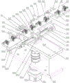
FIG. 2 is a three-dimensional schematic view of the pitch turret of FIG. 1;
FIG. 3 is a three-dimensional schematic view of the master batch table of FIG. 2;
FIG. 4 is a three-dimensional schematic view of the mobile material table shown in FIG. 2;
FIG. 5 is a three-dimensional schematic representation of Bobbin shown in FIG. 2;
FIG. 6 is a three-dimensional schematic view of the material swinging table shown in FIG. 1;
fig. 7 is a three-dimensional schematic view of the gripping transfer machine shown in fig. 1;
FIG. 8 is a three-dimensional schematic view of the clamp and pulling assembly of FIG. 7;
FIG. 9 is a three-dimensional schematic view of the left clamp arm and pull assembly shown in FIG. 8;
FIG. 10 is a three-dimensional schematic view of the right clamp arm and pulling assembly of FIG. 8;
FIG. 11 is a three-dimensional schematic diagram of the XYZ moving module shown in FIG. 7;
FIG. 12 is a three-dimensional schematic view of the first clamping module shown in FIG. 1;
FIG. 13 is a three-dimensional schematic view of the upper clamp block of FIG. 12;
FIG. 14 is a three-dimensional schematic view of the side clamp block of FIG. 12;
the pipe comprises a Bobbin00, a hollow pipe body 001, an upper retainer ring body 002 and a lower retainer ring body 003; front PIN 004, right end block 005, left end block 006, upper boss 007, positioning hole 008 and rear PIN 009;
the device comprises a variable-pitch rotating table 01, a main material table 011, an upper substrate 0100, an upper wing plate 0101, a lower substrate 0102, a first positioning groove 0103, a product jig 0110, an adapter plate 0111, a top block 0112, an upper lug 0113, a limit stop 0114, a positioning column 0115, a movable material table 012, a vertical groove 0121, a heightening table 0122, a horizontal groove 0123, a second positioning groove 0124, a variable-pitch cylinder 013, a second sliding block 014, a linear sliding rail 015, a corner part 016, a rotating shaft 0161, a servo motor 0162, a seated bearing 0163, a coupler 0164, a main frame 017 and a position sensor 018, wherein the main material table comprises a main material table, a lower flange and; cutting the PIN 02; a frame 03;
the material receiving device comprises a transfer material placing table 04, a material receiving jig 041, a rotating shaft 042, a transfer frame 043, a transfer motor 044, a bearing with a seat 045 and a heightening table 046;
the clamping and transferring machine 05, a clamp 051, a left clamping arm 1 and a left arc groove 11; the right clamping arm 2, the right arc groove 21, the pulling assembly 052, the pulling cylinder 3, the moving plate 4 and the first sliding block 5; an XYZ moving module 053, an X-axis assembly 6, a first servo linear module 61, a first slide rail slider assembly 62, a first movable plate 63, a Y-axis assembly 7, a second servo linear module 71, a second slide rail slider assembly 72, a second movable plate 73, a Z-axis assembly 8, a third servo linear module 81 and a vertical seat 82; the device comprises a clamping seat 9, a lower flat plate 91, a vertical wall plate 92, a first guide rail 93, a rear connecting plate 94, a first cylinder plate 95, a second cylinder plate 96 and a limiting seat 97; a blanking module 06; a pin inserting machine 07; a blanking part 08 of the injection molding machine;
the device comprises a first clamping module 09, an upper clamping block 091, a through hole 0911, a counter bore 0912, a first avoiding groove 0913 and a second avoiding groove 0914; a side clamping block 092, an arc surface 0921 and a limit stop 0922; a clamping jaw cylinder 093, a vertical base plate 094, an upper link plate 095, a side link block 096, a lower lug plate 0961, a guide bracket 097, a linear bearing 0971, a guide shaft 0972, an upper link plate 0973, a lower link plate 0974, an inner guide shaft 0975, an upper seat 0976 and a spring 0977.
Detailed Description
The present invention will be described in further detail with reference to the accompanying drawings. It should be noted that the terms "front," "back," "left," "right," "upper" and "lower" used in the following description refer to directions in the drawings, and the terms "inner" and "outer" refer to directions toward and away from, respectively, the geometric center of a particular component.
Fig. 1 to 14 schematically show an automatic PIN cutting assembly line for an injection molding product Bobbin according to an embodiment of the present invention. As shown in the figure, the device comprises a variable pitch rotary table 01, a PIN cutting machine 02 and a transfer material placing table 04 which are sequentially and transversely arranged on the rear side of a rack 03 from right to left, wherein the variable pitch rotary table 01, the PIN cutting machine 02 and the transfer material placing table 04 are provided with material levels n of Bobbin00 with the same number, the longitudinal centerline intervals m of the variable pitch rotary table 01, the PIN cutting machine 02 and the transfer material placing table 04 are the same,
the injection molding machine blanking part 08 is independently arranged on the right side of the rack 03, the injection molding machine blanking part 08 comprises two rows of n/2 rows of first clamping modules 09, the arrangement of the first clamping modules 09 is the same as that of Bobbin00 in a finished product cavity of the injection molding machine, and the first clamping modules 09 can clamp the Bobbin00 in the injection molding machine at one time;
the variable-pitch rotary table 01 rotates to the longitudinal direction, the distance is changed to the maximum, the material level distribution at two ends of the variable-pitch rotary table 01 is the same as the arrangement of the row of first material clamping modules 09, and the first material clamping modules 09 place two rows of Bobbin00 at the material levels at two ends of the variable-pitch rotary table 01 in sequence; the variable-pitch rotary table 01 rotates to the transverse direction and the variable pitch is minimum, and the material level arrangement of the variable-pitch rotary table 01 is the same as the material level arrangement of the PIN cutter 02;
the PIN cutting machine 02 simultaneously cuts off front PIN feet 004 and rear PIN feet 009 of all Bobbin00 on two sides;
the clamping and transferring machine 05 comprises a plurality of groups of clamps 051 and an XYZ moving module 053, the XYZ moving module 053 is fixed on the front side of the rack 03, and two Z shaft assemblies 8 of the XYZ moving module 053 are respectively connected with two clamping seats 9; the distance between the two clamping seats 9 and the distance between the two Z shaft assemblies 8 are both m; n groups of clamps 051 are fixed on each clamping seat 9, each group of clamps 051 can clamp or release one Bobbin00, the clamping and transferring machine 05 can simultaneously take n Bobbins 00 from the variable-pitch rotary table 01 and the PIN cutting machine 02 or simultaneously place n Bobbins 00 on the PIN cutting machine 02 and the transfer material placing table 04,
the clamp 051 comprises a left clamping arm 1 and a right clamping arm 2, the lower surface and the front side surface of a clamping seat 9 are both connected with a moving plate 4 in a sliding manner, n left clamping arms 1 are connected with the lower surface of the moving plate 4 horizontally arranged below at equal intervals, n right clamping arms 2 are connected with the side surface of the moving plate 4 vertically arranged above at equal intervals, and the two moving plates 4 can move oppositely or away from each other, so that the clamping or the releasing of the Bobbin00 of the left clamping arm 1 and the right clamping arm 2 is realized;
the middle rotating material placing table 04 comprises a plurality of material receiving jigs 041, one group of the material receiving jigs 041 at odd-numbered positions or even-numbered positions is fixedly arranged, the other group of the material receiving jigs 041 is rotatably arranged, and the rotatably arranged material receiving jigs 041 are rotated 180 degrees, so that the positions of the Bobbin00 in the two groups of material receiving jigs 041 are the same;
the blanking module 06 is arranged at the rear side of the transfer material placing table 04, and a plurality of first material clamping modules 09 are arranged on the blanking module 06;
the pin inserting machine 07 is independently arranged on the left of the rack 03, and the blanking module 06 clamps and places the Bobbin00 on the transfer material placing table 04 on a track of the pin inserting machine 07. The beneficial effects are as follows: firstly, the device realizes automatic production of automatic blanking, positioning, feeding, PIN cutting, blanking and transfer positioning, has high speed and high efficiency, is suitable for large-scale continuous production, avoids human factor errors and protects operating personnel and products; secondly, the variable-pitch rotary table 01 and the first material clamping module 09 realize that products on the casting equipment are directly and completely taken down, are subjected to variable-pitch arrangement and positioning, and are directly loaded and unloaded, so that the phenomenon that too many transposition processes are added in the previous period is avoided, and the production efficiency can be greatly improved; thirdly, the clamping transfer machine 05 can simultaneously carry out feeding or discharging operation, so that the speed is further increased, conversion is carried out, and products enter the detection position in order at the same angle; fourthly, the special clamp 051 can flexibly clamp the Bobbin super, and the pin inserting machine 07 receives materials in order.
Preferably, the gripping transfer machine 05 further comprises a pulling assembly 052, and the pulling assembly 052 comprises two pulling cylinders 3 with telescopic ends transversely arranged oppositely; the telescopic ends of the pulling cylinders 3 are respectively connected with a moving plate 4;
the upper surface of the lower moving plate 4 and the back side surface of the vertical moving plate 4 are provided with a plurality of first sliding blocks 5; the front side of the holder 9 is connected with a transverse first guide rail 93, and the first guide rail 93 is connected with a plurality of first sliding blocks 5 in a sliding manner. The device adopts a linear guide rail slide block and a pulling assembly 02 of which the cylinder outputs linear motion, so that the material can be simultaneously taken from a feeding station, a PIN cutting table and a blanking jig among the feeding station, the PIN cutting table and the blanking jig, or the products can be simultaneously placed on the PIN cutting table and the blanking jig; the beneficial effects are as follows: specially designed pulling assembly 02, the slide rail slider direction, the straight line output precision is high, can accomplish the high accuracy pulling of a plurality of products simultaneously.
Preferably, the holder 9 comprises a lower plate 91 and a vertical wall plate 92 vertically connected to each other, a first transverse guide rail 93 is connected to the lower surface of the lower plate 91 and the front side of the vertical wall plate 92,
the cylinder barrel of one pulling cylinder 3 is fixed on the lower flat plate 91 through a first cylinder plate 95, the cylinder barrel of the other pulling cylinder 3 is fixed on the vertical wall plate 92 through the first cylinder plate 95, and the telescopic ends of the two pulling cylinders 3 are respectively connected with the moving plate 4 through a second cylinder plate 96; a limiting seat 97 opposite to the second cylinder plate 96 is respectively arranged on the lower flat plate 91 or the vertical wall plate 92;
a floating joint is provided between the telescopic end of the pulling cylinder 3 and the second cylinder plate 96.
The rear end of the lower plate 91 is vertically connected to a rear yoke plate 94, and the rear yoke plate 94 is connected to the moving end of the Z-axis assembly 8. The specially-made clamping seat 9 is adopted, the stability is high, the two moving plates 4 are arranged on the upper surface and the front side face of the clamping seat 9, the structure is compact, high parallelism can be achieved, and high-precision stable grabbing and blanking of a plurality of products can be achieved.
Preferably, the two first cylinder plates 95 are respectively provided with a third positioning slot having the same width as the lower plate 91 or the vertical wall plate 92, and the second cylinder plate 96 is provided with a fourth positioning slot having the same width as the moving plate 4.
Preferably, the holder 9 further comprises an upper holding plate, a front side of the upper holding plate is screwed with the vertical base plate 91, a rear side of the upper holding plate is screwed with the rear yoke plate 94, and a lower surface of the upper holding plate is screwed with the lower flat plate 91.
Preferably, the left clamping arm 1 comprises a left clamping head for horizontally and longitudinally arranging cloth, a left arc groove 11 is formed in the right side surface of the left clamping head, the right clamping arm 2 comprises a right clamping head for horizontally and longitudinally arranging cloth, a right arc groove 21 is formed in the left side surface of the right clamping head, and the left arc groove 11 and the right arc groove 21 are horizontally and symmetrically arranged and are respectively matched with the outer contour of the hollow pipe body 001 of Bobbin 00; adopt anchor clamps 051 that the characteristic set up, left arm lock 1 and right arm lock 2 cooperate with the product, realized that the high accuracy of product is got material
An upper retainer ring body 002 is formed at the upper end of the hollow tube body 001, a lower retainer ring body 003 is formed at the lower end of the hollow tube body 001, and the distance between the upper retainer ring body 002 and the lower retainer ring body 003 is larger than the height of the left chuck and the right chuck;
the left clamping arm 1 and the right clamping arm 2 are made of polyurethane or acrylic materials with certain elasticity and micro deformation.
The left arc groove 11 and the right arc groove 21 are adhered with arc sheets made of polyurethane or acrylic. The beneficial effects are as follows: the product surface is protected, and the undesirable characteristics such as pressure loss and the like are avoided.
Preferably, the rear end of the left chuck vertically extends upwards to form a left vertical section, and the upper end of the left vertical section vertically extends backwards to form a rear connection section;
the rear end of the right chuck vertically extends upwards to form a right vertical section, the upper end of the right vertical section vertically extends backwards to form a middle flat section, and the rear end of the middle flat section vertically extends upwards to form an upper connection section.
The two moving plates 4 move towards or away from each other, each group of left clamping arm 1 and right clamping arm 2 move towards or away from each other simultaneously to clamp the hollow tube body 001 or release the hollow tube body 001,
a plurality of first positioning grooves are formed in one surface of the moving plate 4 at equal intervals, second positioning grooves are formed in the opposite surface of the moving plate, and the widths of the upper connection sections of the first positioning grooves and the left clamping arm 1 are the same as the widths of the rear connection sections of the right clamping arm 2; the second positioning groove has the same width as the first slider 5.
Preferably, the XYZ translation module 053 comprises an X-axis assembly 6, a Y-axis assembly 7 and two Z-axis assemblies 8, the X-axis assembly 6 comprising a first servo linear module 61 disposed laterally; the Y-axis assembly 7 comprises a second servo linear module 71 which is arranged longitudinally; the Z-axis assembly 8 comprises a third servo linear module 81 which is vertically arranged;
the X-axis assembly 6 further comprises a first sliding rail sliding block assembly 62 which is transversely arranged, and the lower part of the first movable plate 63 is respectively and transversely connected with the first servo linear module 61 and the moving end of the first sliding rail sliding block assembly 62;
the Y-axis assembly 7 comprises a second sliding rail sliding block assembly 72 which is longitudinally arranged, the fixed ends of a second servo linear module 71 and the second sliding rail sliding block assembly 72 are respectively connected to the first movable plate 63, and the lower end of a second movable plate 73 is respectively and longitudinally connected with the movable ends of the second servo linear module 71 and the second sliding rail sliding block assembly 72;
the Z-axis assembly 8 further includes vertical seats 82, the two vertical seats 82 are vertically connected to the second movable plate 73, the front side of the vertical seat 82 is vertically connected to the third servo linear module 81, and the moving end of the third servo linear module 81 is connected to the rear connecting plate 94. The XYZ moving module 03 drives the holder 9 and the fixture 01 on the holder 9 to perform linear motions in the X, Y and Z directions. The beneficial effects are as follows: the servo linear module is high in moving precision, high in product discharging position, soft in action and free of shaking.
Preferably, the first clamping module 09 includes a soft and elastic upper clamping block 091, two side clamping blocks 092, a clamping jaw cylinder 093, and a vertical base plate 094,
the upper clamping blocks 091 are vertically and horizontally arranged, the profile characteristics of the upper surfaces of the upper baffle ring bodies 002 of the upper clamping blocks 091 and the Bobbin00 are matched, the upper clamping blocks 091 are in threaded connection with the lower surface of the upper connecting plate 095, and the upper connecting plate 095 is connected to the middle of the lower surface of the vertical base plate 094;
the two vertical side clamping blocks 092 are symmetrically arranged on two sides of the upper clamping block 091, the upper end of the inner side face of each side clamping block 092 is provided with an arc surface 0921, the lower end of the inner side face of each side clamping block 092 protrudes inwards to form a limit stop 0922, the arc surfaces 0921 are matched with the circumferential surface of the upper retainer ring body 002, and the limit stops 0922 are positioned below the upper retainer ring body 002;
the left side of the lower end of the side connecting block 096 is a lower lug plate 0961, the right side of the lower end of the side connecting block 096 is a rectangular notch, the side clamping block 092 is located in the notch and connected with the inner side face of the lower lug plate 0961, the rectangular upper end of the side connecting block 096 is a positioning groove, and the positioning groove is in inserting fit with a rectangular claw of the clamping jaw air cylinder 093 and is fixed through a transverse threaded piece;
the cylinder of the clamping jaw cylinder 093 is fixed to the front side of the vertical base plate 094. The device realizes automatic clamping and discharging of the Bobbin 00; the upper clamping block 091 and the two side clamping blocks 092 which are matched with the Bobbin00 product are adopted to perform two-side and upside laminating clamping to obtain the product, and a special clamping jaw cylinder 093 is adopted to realize stable and soft clamping action, so that the automatic stable accurate safe clamping is realized, and the beneficial effects are that: firstly, automatic clamping and placing are realized, the speed is high, the efficiency is high, the automatic clamping and placing device is suitable for large-scale continuous operation, unmanned operation is realized, human factor errors are eliminated, and the safety of operating personnel is ensured; secondly, the arc surfaces 0921 of the upper clamping block 091 and the side clamping blocks 092 are respectively matched with the upper surface of the Bobbin00 and the upper retainer ring body 002, and the limit stop 0922 is used for positioning downwards, so that good clamping and positioning are realized, and the phenomenon of moving up and down or falling off in the moving process is prevented; thirdly, the upper clamping block 091 and the side clamping blocks 092 are soft and elastic materials, so that the surface of the product can be protected, and the surface quality of the product can be improved; fourthly, the side connecting block 096 adopts a structure of the lower lug block 0961 and the notch, so that the size of the equipment is reduced, a larger space is provided for the arrangement of other equipment, and the applicability of the equipment is improved; fifthly, the rectangular claw of the clamping jaw cylinder 093 is matched with the positioning groove 0962, and the rectangular structure can prevent circumferential rotation, so that the axial movement and the circumferential rotation are constrained to ensure the installation precision, and a good foundation is improved for subsequent clamping.
Preferably, the upper retainer ring body 002 is provided with a right end block 005 which is integrally protruded and a left end block 006 which is partially protruded, an upper convex column 007 is formed on the upper surface of the right end block 005,
the upper clamping block 091 is provided with a first avoiding groove 0913 matched with the left end block 006, a second avoiding groove 0914 matched with the right end block 005 and a through hole 0911 corresponding to the position of the upper convex column 007, and the through hole 0911 is in large clearance fit with the upper convex column 007; the beneficial effects are as follows: this setting has further improved the positioning accuracy of product, realizes that the high accuracy snatchs and removes.
And the two ends of the lower surface of the upper clamping block 091 are also provided with positioning pins, and the positioning pins correspond to the positioning holes 008 on the upper retainer ring body 002. The beneficial effects are as follows: the positioning pin can improve the positioning accuracy.
Preferably, the two ends of the lower surface of the upper clamping block 091 are further provided with the vacuumizing nozzles, the lower surface of the vacuumizing nozzle is flush with the lower surface of the upper clamping block 091, and the vacuumizing nozzle can be attached to and adsorb the ring body of the upper retainer ring body 002. The beneficial effects are as follows: the action that the high-end upper surface of product was inhaled tight location and the both sides clamp of bottom is got can be guaranteed to the suction nozzle, has better clamp and gets the effect, does not have the rocking phenomenon that one end drops and cause in the removal, realizes that good high accuracy moves the material.
Preferably, the lower surface of the upper clamp block 091 is provided with a touch sensor, and the touch sensor detects that the lower surface of the upper clamp block 091 is attached to the upper surface of the Bobbin00 and does not continuously downwards apply pressure to the upper surface of the Bobbin 00. The beneficial effects are as follows: further protecting the product.
Preferably, the upper clamping block 091 and the side clamping block 092 are made of rubber or high-strength rubber. The beneficial effects are as follows: the polyurethane PU elastomer of the super glue has the rigidity of plastics and the elasticity of rubber; the damping rubber has the characteristics of good damping, silence, shock absorption, wear resistance, high temperature resistance and the like.
Preferably, the lateral clamping block 092 has a transverse stepped through hole, an outer large diameter hole of the transverse stepped through hole penetrates through the circular arc clamping surface 0921 and the limit stopper 0922, and a cylindrical head screw is located in the transverse stepped through hole and a front end of the cylindrical head screw is screwed into a lower threaded hole of the lateral coupling block 096. The beneficial effects are as follows: simple structure reduces the product size.
Preferably, a first rectangular groove is formed in the middle of the lower surface of the vertical base plate 094, the width of the first rectangular groove is the same as that of the upper link plate 095, the upper link plate 095 is provided with a first stepped through hole, and a cylindrical head screw is located in the first stepped through hole and screwed into a threaded blind hole of the first rectangular groove; two side surfaces of the upper connecting plate 095 are provided with second rectangular grooves, and the width of each second rectangular groove is larger than that of each rectangular claw; the beneficial effects are as follows: the structure improves the installation precision and reduces the size of the equipment.
The upper clamping block 091 is provided with a countersunk hole 0912, and a countersunk screw passes through the countersunk hole 0912 and is screwed into a threaded hole of the upper link plate 095.
Preferably, the upper end of the cylinder barrel of the clamping jaw cylinder 093 and the upper side surface of the vertical base plate 094 are in threaded connection with the lower connecting plate 0974;
the guide bracket 097 includes two sets of linear bearings 0971 and guide shafts 0972 that are axially fitted to each other, and the upper ends of the two guide shafts 0972 are vertically connected to both ends of the upper link plate 0973, respectively, and the lower ends thereof are vertically connected to both ends of the lower link plate 0974, respectively, thereby forming a rectangular bracket.
The guide bracket 097 further includes an upper seat 0976 fixedly disposed thereon, two inner guide shafts 0975 slide up and down along the vertical guide holes of the upper seat 0976, the lower ends of the two inner guide shafts 0975 are vertically connected to the lower coupling plate 0974, the outer wall of the inner guide shaft 0976 is sleeved with a spring 0977, the lower end of the spring 0977 is attached to the lower coupling plate 0974, and the upper end of the spring 0976 is attached to the upper seat 0976. The device has realized that the automatic clamp of a plurality of products is got, is removed and places, adopts guide bracket to carry out the high accuracy and reciprocates, and the elastic seat cushions each difference stress of getting the material module.
Preferably, the variable-pitch rotary table 01 comprises a main material table 011 and movable material tables 012 which are arranged outside the left end and the right end of the main material table 011, wherein a plurality of product jigs 0110 are arranged on the upper surfaces of the main material table 011 and the movable material tables 012, and the product jigs 0110 are matched with the outlines of Bobbin 00; on the main material platform 011 and the movable material platform 012, the distance between the adjacent product jigs 0110 is r, the distance between the main material platform 011 and the movable material platform 012 between the adjacent product jigs 0110 is s,
the front side surface and the rear side surface of the main material platform 011 are both connected with a transverse pitch-variable cylinder 013, the telescopic ends of the two pitch-variable cylinders 013 are arranged oppositely and are respectively connected with a movable material platform 012, and the distance s can be changed into the distance r by pulling the Qigong 013 to act, so that the distances between all the product jigs are the same;
two transverse second sliding blocks 014 are respectively fixed on the front side surface and the rear side surface of the main material platform 011, each second sliding block 014 is in sliding fit with a transversely arranged linear sliding rail 015, the other end of each linear sliding rail 015 is connected with a movable material platform 012,
the lower surface of the main material platform 011 is connected with the upper end of the corner part 016, the corner part 016 is connected onto the main frame 017, the lower surface of the main material platform 011 is fixed with an induction sheet, the upper flat plate of the main frame 017 is fixed with the position sensor 018 matched with the induction sheet, the corner part 016 is started, and the product jig 0110 can be converted from a material swinging angle to a material feeding angle.
The device has realized automatic variable-pitch array, and corner portion 016 has realized that loading attachment and unloader can the multi-angle selection, is fit for among more process equipment, and its beneficial effect is: firstly, automatic variable-pitch arrangement is realized, the speed is high, the effect is good, large-scale continuous operation can be realized, the safety of workers is protected, and products are protected; secondly, the main material platform 011 and the movable material platform 012 which are designed in a split mode are adopted, a sliding rail sliding block is used for guiding, a pitch-variable cylinder 013 is pulled linearly, good linear pitch variation can be carried out, the pitch variation precision is high, and left and right deviation is avoided; thirdly, the sensing sheet is matched with the product position sensor 018, so that the rotation precision is high; fourthly, the product jig 0110 is matched with the Bobbin00, accurate positioning can be achieved, and a good positioning reference is provided for material cutting.
Preferably, the corner portion 016 includes a rotation shaft 0161 and a servo motor 0162, the upper end of the rotation shaft 0161 is connected to the middle of the lower surface of the main material table 011, the middle of the rotation shaft 0161 is rotatably connected to the upper plate through a bearing 0163 with a seat, the lower end of the rotation shaft 61 is connected to a coupling 64 connected to an extending shaft of the servo motor 0162,
the servo motor 0162 is fixed on the lower surface of the lower plate of the main frame 017. The beneficial effects are as follows: the servo motor has high rotation precision, soft start and stop actions, and the elastic coupling can buffer certain impact force.
Preferably, a longitudinal arrangement's keysets 0111 is all connected at the front and back both ends of major ingredient platform 011, and a longitudinal arrangement's kicking block 0112 is connected to the leading flank or the trailing flank of removal material platform 012, and the cylinder vertical fixation of displacement cylinder 013 is in keysets 0111, and kicking block 0112 is connected perpendicularly to displacement cylinder 013's telescopic link.
Preferably, the telescopic rod is provided with a floating joint, and the floating joint is in threaded connection with the transverse threaded hole of the top block 0112. The beneficial effects are as follows: the structure has high installation precision, and the floating joint can adjust certain size.
Preferably, a vertical groove 0121 is formed on the front side or the rear side of the moving material table 012, and the width of the vertical groove 0121 is the same as that of the top block 0112. The beneficial effects are as follows: the vertical groove 0121 has a good positioning structure, so that the straightness of the variable-pitch cylinder 013 is guaranteed.
Preferably, the upper end of adapter plate 0111 outwards extends and forms an upper ear piece 0113, and upper ear piece 0113 threaded connection is at main material platform 011 upper surface. The beneficial effects are as follows: the upper lug block 0113 can improve a good positioning foundation.
Preferably, the main material platform 011 is in an i-shaped structure, one end of an upper substrate 0100 of the main material platform 011 extends forward to form an upper wing plate 0101, the other end of the upper substrate 0100 extends backward to form an upper wing plate 0101, and a second slider 014 is installed on the lower surface of each upper wing plate 0101; the beneficial effects are as follows: the main material platform 011 has good positioning precision, compact structure, small volume, good rigidity and no shake under transverse load.
The linear sliding rail 015 moves in a C-shaped groove below the upper wing plate 0101,
at the opposite end of the upper wing plate 0101, a limit stop 0114 is fixed on the lower substrate 0102 of the main material platform 011. The beneficial effects are as follows: limit stop 0114 has good spacing benchmark, prevents the maloperation that excessive aversion caused.
Preferably, the heightening table 0122 is formed on one side of the lower surface of the moving material table 012, the transverse groove 0123 is formed on the lower surface of the heightening table 0122, and the linear sliding rail 015 is in threaded connection with the transverse groove 0123. The beneficial effects are as follows: the transverse groove 0123 can provide a good positioning reference for the linear slide rail 5, and has high installation accuracy and high linearity.
Preferably, major ingredient platform 011 upper surface is equipped with first constant head tank 0103, removes material platform 012 upper surface and all is equipped with second constant head tank 0124, and first constant head tank 0103 and second constant head tank 0124 are located same high-level in and on same straight line, and first constant head tank 103 and second constant head tank 0124's screw hole and a plurality of product tool 0110's ladder through-hole adopt cylinder head screw to connect. The beneficial effects are as follows: this setting can make all product tools 0110 in the coplanar height, has guaranteed that all products have good position degree.
Preferably, a positioning column 0115 is formed on the upper surface of the product jig 0110, the inner holes of the hollow tube 001 of the positioning columns 0115 and the hollow tube 001 of the Bobbin00 are matched, and the front side surface and the rear side surface of the product jig 0110 are respectively attached to the front PIN foot 004 and the rear PIN foot 009 of the Bobbin 00. The beneficial effects are as follows: this product tool 0110 and Bobbin00 that sets up adopt the hole of reference column 0115, hollow body 001 to cooperate, can realize that the good location of product is fixed, and PIN foot 004, back PIN foot 009 before product tool 0110's leading flank and trailing flank laminate respectively can prevent that the product from rotating, and the rotation in-process does not have the position and removes, protects the product, provides good basis for getting the material simultaneously.
The transfer material placing table 04 further comprises a transfer frame 043, the transfer frame 043 is rotatably connected with the rotating shaft 042 through a bearing with a seat 045, one side of each bearing with a seat 045 is provided with a heightening table 046, and the material receiving jig 041 is respectively connected to the upper end of the rotating shaft 042 or the heightening table 046; the lower end of each rotating shaft 042 is connected with a transfer motor 044 through a coupling. The beneficial effects are as follows: this transfer pendulum material platform 04 can be fast the high accuracy for the product sequencing.
What has been described above are only some embodiments of the invention. For those skilled in the art, without departing from the inventive concept, several modifications and improvements can be made, which are within the scope of the invention.
Claims (10)
1. An automatic PIN cutting assembly line for injection molding products Bobbin is characterized by comprising a variable-pitch rotary table (01), a PIN cutting machine (02) and a transfer material placing table (04) which are sequentially and transversely arranged on the rear side of a rack (03) from right to left, wherein the variable-pitch rotary table (01), the PIN cutting machine (02) and the transfer material placing table (04) are provided with the same number of material positions of Bobbin (00), and the longitudinal center line distances of the variable-pitch rotary table (01), the PIN cutting machine (02) and the transfer material placing table (04) are the same,
the injection molding machine blanking part (08) is independently arranged on the right side of the rack (03), and the injection molding machine blanking part (08) comprises two rows of first clamping modules (09) in a plurality of rows;
the clamping and transferring machine (05) comprises a plurality of groups of clamps (051) and an XYZ moving module (053), the XYZ moving module (053) is fixed on the front side of the rack (03), and two Z shaft assemblies (8) of the XYZ moving module (053) are respectively connected with two clamping seats (9); the distance between the two clamping seats (9) and the distance between the two Z shaft assemblies (8) are the same; a plurality of groups of clamps (051) are fixed on each clamp seat (9),
the clamp (051) comprises a left clamp arm (1) and a right clamp arm (2), the lower surface and the front side surface of the clamp seat (9) are both connected with a moving plate (4) in a sliding mode, a plurality of left clamp arms (1) are connected with the lower surface of the moving plate (4) which is horizontally arranged at the lower part at equal intervals, and a plurality of right clamp arms (2) are connected with the side surface of the moving plate (4) which is vertically arranged at the upper part at equal intervals;
the transfer material placing table (04) comprises a plurality of material receiving jigs (041), one group of the material receiving jigs (041) at odd-numbered positions or even-numbered positions is fixedly arranged, and the other group of the material receiving jigs is rotatably arranged;
the blanking module (06) is arranged at the rear side of the transfer material placing table (04), and a plurality of first material clamping modules (09) are arranged on the blanking module (06);
the pin inserting machine (07) is independently arranged on the left side of the rack (03), and the blanking module (06) clamps and places the Bobbin (00) on the transfer material placing table (04) on a track of the pin inserting machine (07).
2. The automatic PIN cutting production line of an injection molding product Bobbin according to claim 1, wherein the gripping transfer machine (05) further comprises a pulling assembly (052), and the pulling assembly (052) comprises two pulling cylinders (3) with telescopic ends transversely arranged oppositely; the telescopic ends of the pulling cylinders (3) are respectively connected with the moving plate (4);
a plurality of first sliding blocks (5) are arranged on the upper surface of the lower moving plate (4) and the vertical rear side surface of the moving plate (4); the front side surface of the clamping seat (9) is connected with a transverse first guide rail (93), and the first guide rail (93) is connected with a plurality of first sliding blocks (5) in a sliding manner.
3. An automatic PIN cutting line for an injection molding product Bobbin according to claim 2, wherein said clamping base (9) comprises a lower plate (91) and a vertical wall plate (92) vertically connected with each other, a lower surface of said lower plate (91) and a front side of said vertical wall plate (92) are connected with a transverse said first guide rail (93),
the cylinder barrel of one pulling cylinder (3) is fixed on the lower flat plate (91) through a first cylinder plate (95), the cylinder barrel of the other pulling cylinder (3) is fixed on the vertical wall plate (92) through the first cylinder plate (95), and the telescopic ends of the two pulling cylinders (3) are respectively connected with the moving plate (4) through a second cylinder plate (96); and the lower flat plate (91) or the vertical wall plate (92) is respectively provided with a limiting seat (97) opposite to the second cylinder plate (96).
4. The automatic PIN cutting production line for the injection molding product Bobbin according to claim 2, wherein a left circular arc groove (11) is formed in the right side surface of the left clamping arm (1), a right circular arc groove (21) is formed in the left side surface of the right clamping arm (2), and the left circular arc groove (11) and the right circular arc groove (21) are horizontally and symmetrically arranged and are respectively matched with the outer contour of the hollow pipe body (001) of the Bobbin (00); an upper retainer ring body (002) is formed at the upper end of the hollow pipe body (001) and a lower retainer ring body (003) is formed at the lower end of the hollow pipe body.
5. An automated PIN cutting assembly line for injection molding products Bobbin according to claim 1, wherein the XYZ movement module (053) comprises an X-axis assembly (6), a Y-axis assembly (7) and two Z-axis assemblies (8), the X-axis assembly (6) comprising a first servo linear module (61) arranged laterally; the Y-axis assembly (7) comprises a second servo linear module (71) which is longitudinally arranged; the Z-axis assembly (8) comprises a third servo linear module (81) which is vertically arranged.
6. An automatic PIN cutting line for injection molding products Bobbin according to claim 4, wherein the first clamping module (09) comprises an upper clamping block (091), the upper clamping block (091) is screwed on the lower surface of an upper connecting plate (095), and the upper connecting plate (095) is connected in the middle of the lower surface of a vertical base plate (094); two vertical side clamping blocks (092) are symmetrically arranged at two sides of the upper clamping block (091), the upper end of the inner side surface of each side clamping block (092) is provided with an arc surface (0921), and the lower end of the inner side surface of each side clamping block (092) protrudes inwards to form a limit stop (0922);
the left side of the lower end of the side connecting block (096) is a lower ear plate (0961) and the right side is a rectangular notch, the side clamping block (092) is positioned in the notch and connected with the inner side surface of the lower ear plate (0961),
the positioning groove at the upper end of the side connecting block (096) is in plug fit with the rectangular claw of the clamping jaw cylinder (093); the cylinder barrel of the clamping jaw cylinder (093) is fixed on the front side face of the vertical base plate (094).
7. An automatic PIN cutting line for injection molding products Bobbin according to claim 6, wherein the upper retainer ring body (002) is provided with an integrally convex right end block (005) and a partially convex left end block (006), the upper surface of the right end block (005) is formed with an upper convex column (007),
the upper clamping block (091) is provided with a first avoidance groove (0913) matched with the left end block (006), a second avoidance groove (0914) matched with the right end block (005) and a through hole (0911) corresponding to the upper convex column (007), and the through hole (0911) is in large clearance fit with the upper convex column (007); and positioning pins are further mounted at two ends of the lower surface of the upper clamping block (091), and correspond to the positioning holes (008) in the upper retainer ring body (002).
8. The automatic PIN cutting line for injection molding products Bobbin according to claim 7, wherein both ends of the lower surface of the upper clamp block (091) are further provided with vacuum suction nozzles,
the lower surface of the upper clamping block (091) is provided with a touch sensor.
9. The automatic PIN cutting production line of an injection molding product Bobbin according to claim 1, characterized in that the variable pitch rotary table (01) comprises a main material table (011) and a movable material table (012) arranged outside the left and right ends of the main material table (011), wherein a plurality of product jigs (0110) are arranged on the upper surfaces of the main material table (011) and the movable material table (012);
the front side surface and the rear side surface of the main material platform (011) are both connected with a transverse pitch-variable cylinder (013), and the telescopic ends of the two pitch-variable cylinders (013) are arranged oppositely and are respectively connected with one movable material platform (012); two transverse second sliding blocks (014) are respectively fixed on the front side surface and the rear side surface of the main material platform (011), each second sliding block (014) is in sliding fit with one transversely-arranged linear sliding rail (015), the other end of each linear sliding rail (015) is connected with one movable material platform (012),
the lower surface of the main material platform (011) is connected with the upper end of a corner part (016), and the corner part (016) is connected to the main frame (017).
10. An automatic PIN cutting line for injection molding products Bobbin according to claim 9, wherein one end of an upper base plate (0100) of the main material table (011) extends forward to form an upper wing plate (0101) and the other end extends backward to form the upper wing plate (0101), and the second slider (014) is installed on the lower surface of each upper wing plate (0101); the lower surface of the movable material table (012) forms a transverse groove (0123), and the linear sliding rail (015) is in threaded connection with the inside of the transverse groove (0123).
Priority Applications (1)
| Application Number | Priority Date | Filing Date | Title |
|---|---|---|---|
| CN202022041513.0U CN213459401U (en) | 2020-09-17 | 2020-09-17 | Automatic PIN foot cutting assembly line for injection molding product Bobbin |
Applications Claiming Priority (1)
| Application Number | Priority Date | Filing Date | Title |
|---|---|---|---|
| CN202022041513.0U CN213459401U (en) | 2020-09-17 | 2020-09-17 | Automatic PIN foot cutting assembly line for injection molding product Bobbin |
Publications (1)
| Publication Number | Publication Date |
|---|---|
| CN213459401U true CN213459401U (en) | 2021-06-15 |
Family
ID=76324638
Family Applications (1)
| Application Number | Title | Priority Date | Filing Date |
|---|---|---|---|
| CN202022041513.0U Active CN213459401U (en) | 2020-09-17 | 2020-09-17 | Automatic PIN foot cutting assembly line for injection molding product Bobbin |
Country Status (1)
| Country | Link |
|---|---|
| CN (1) | CN213459401U (en) |
-
2020
- 2020-09-17 CN CN202022041513.0U patent/CN213459401U/en active Active
Similar Documents
| Publication | Publication Date | Title |
|---|---|---|
| CN106315177A (en) | Feeding device for automated production line | |
| US9522451B2 (en) | Vertical machining center | |
| CN110039331B (en) | Exchange workbench with standing function | |
| CN104308626A (en) | Cutter changing device | |
| CN102398224B (en) | Orthogonal three-axis machine tool | |
| CN213459401U (en) | Automatic PIN foot cutting assembly line for injection molding product Bobbin | |
| CN110405254A (en) | A kind of centre drill hole machine tool | |
| CN112216496A (en) | Automatic PIN foot cutting assembly line for injection molding product Bobbin | |
| CN113581780A (en) | Double-rail type feeding device | |
| CN210818424U (en) | Double-station processing platform and processing equipment | |
| CN213830178U (en) | Clamping and transferring machine for injection molding product Bobbin | |
| CN211166149U (en) | Engraving and milling machine | |
| CN214418214U (en) | Processing machine tool | |
| CN115431012A (en) | Automatic installation device for sliding table cylinder floating joint and use method | |
| CN111099096B (en) | Foam stripping and stringing machine | |
| CN114473506A (en) | Drilling and chamfering machine | |
| CN102874028A (en) | Three-dimensional carving machine for wood | |
| CN211053927U (en) | Material loading positioning mechanism of engraving and milling machine | |
| CN202192931U (en) | Column engraving machine | |
| CN109333308B (en) | Automatic cutting production line for rolling guide rail | |
| CN211541144U (en) | Car seat slide rail holder ball rigging equipment | |
| CN212666543U (en) | Automatic PIN cutting assembly line for injection molding product Header | |
| CN211414107U (en) | Automatic welding machine with high-precision quick feeding device | |
| CN221065242U (en) | Gantry type machining center machine tool | |
| CN112208073A (en) | Clamping and transferring machine for injection molding product Bobbin |
Legal Events
| Date | Code | Title | Description |
|---|---|---|---|
| GR01 | Patent grant | ||
| GR01 | Patent grant |