CN213054295U - Precision grinding machine for center hole - Google Patents
Precision grinding machine for center hole Download PDFInfo
- Publication number
- CN213054295U CN213054295U CN202021830715.7U CN202021830715U CN213054295U CN 213054295 U CN213054295 U CN 213054295U CN 202021830715 U CN202021830715 U CN 202021830715U CN 213054295 U CN213054295 U CN 213054295U
- Authority
- CN
- China
- Prior art keywords
- sliding plate
- fixedly connected
- supporting
- seat
- support frame
- Prior art date
- Legal status (The legal status is an assumption and is not a legal conclusion. Google has not performed a legal analysis and makes no representation as to the accuracy of the status listed.)
- Active
Links
Images


Abstract
The utility model discloses a centre bore precision grinder, which comprises a frame, frame top one side fixedly connected with support frame, the support frame top is equipped with grinds the mechanism, the frame top is equipped with the lathe bed guide rail, lathe bed guide rail top is equipped with adjustment mechanism, it includes the slide to grind the mechanism, the slide is established at the support frame top, slide and support frame sliding connection, slide top fixedly connected with unit head, unit head one side is equipped with the main shaft, the main shaft runs through the unit head and passes through the bearing rotation with the unit head and be connected, the grinding head is installed to main shaft one end. The utility model discloses a rotate adjusting nut to drive adjusting screw and reciprocate, and then make the screw rod drive the supporting seat and reciprocate, can adjust the height of supporting seat according to the external diameter of pivot, thereby make by the fixed part center of supporting seat and the coincidence of grinding head center, make the utility model discloses can be suitable for the pivot of different external diameters.
Description
Technical Field
The utility model relates to a grind the machine field, concretely relates to centre bore precision lapping machine.
Background
The grinding machine is a grinding machine that grinds the surface of a workpiece with a grinder coated with or embedded with an abrasive. The grinding machine is mainly used for grinding high-precision planes, inner and outer cylindrical surfaces, conical surfaces, spherical surfaces, threaded surfaces and other molded surfaces in workpieces. The main types of grinding machines are disc mills, spindle mills and various special grinding machines.
At present, when a knife roller type part is machined, a central hole of a rotating shaft of the knife roller type part is usually required to be precisely ground, so that the precision requirement of the part is met, however, when the central hole of the existing grinding machine is ground, the existing grinding machine can only be used for machining shafts with the same outer diameter, and the applicability is poor.
Therefore, it is necessary to invent a precision grinder for center hole to solve the above problems.
SUMMERY OF THE UTILITY MODEL
The utility model aims at providing a centre bore precision grinding machine through rotating adjusting nut to drive adjusting screw and reciprocate, and then make the screw rod drive the supporting seat and reciprocate, can adjust the height of supporting seat according to the external diameter of pivot, thereby make by the fixed part center of supporting seat and the coincidence of grinding head center, make the utility model discloses can be suitable for the pivot of different external diameters, with the above-mentioned weak point in the solution technology.
In order to achieve the above object, the present invention provides the following technical solutions: a central hole precision grinding machine comprises a rack, wherein a support frame is fixedly connected to one side of the top of the rack, a grinding mechanism is arranged at the top of the support frame, a lathe bed guide rail is arranged at the top of the rack, and an adjusting mechanism is arranged at the top of the lathe bed guide rail;
the grinding mechanism comprises a sliding plate, the sliding plate is arranged at the top of the support frame and is in sliding connection with the support frame, the top of the sliding plate is fixedly connected with a power head, a main shaft is arranged on one side of the power head, the main shaft penetrates through the power head and is in rotating connection with the power head through a bearing, a grinding head is arranged at one end of the main shaft, a motor is fixedly connected to the bottom of the sliding plate, and an output shaft of the motor is in transmission connection with the other end of;
the adjusting mechanism comprises a sliding plate seat, the sliding plate seat is arranged at the top of the guide rail of the machine body, the sliding plate seat is connected with the guide rail of the machine body in a sliding manner, and a supporting assembly is arranged at the top of the sliding plate seat;
the supporting component comprises a fixing frame, the fixing frame is arranged at the top of the sliding plate seat, the fixing frame is fixedly connected with the sliding plate seat, a supporting seat is arranged at the top of the fixing frame, the supporting seat extends into the fixing frame, the supporting seat is slidably connected with the fixing frame, an adjusting screw is arranged at the bottom of the supporting seat and fixedly connected with the supporting seat, an adjusting nut is sleeved outside the adjusting screw and is in threaded connection with the adjusting screw, the adjusting nut is arranged at the top of the sliding plate seat and is rotatably connected with the sliding plate seat.
Preferably, the supporting seat comprises an upper supporting plate and a lower supporting plate, and the upper supporting plate is fixedly connected with the lower supporting plate through screws.
Preferably, the number of the supporting components is two, the other supporting component is arranged on one side of the supporting frame, and the supporting components are fixedly connected with the rack.
Preferably, a cylinder is arranged on one side, away from the rack, of the support frame, the cylinder is fixedly connected with the support frame, and the output end of the cylinder is in transmission connection with the sliding plate.
Preferably, a tailstock nut is arranged on one side, away from the support frame, of the frame, the tailstock nut is fixedly connected with the frame, a top screw is arranged on one side of the tailstock nut, the top screw penetrates through the tailstock nut and is in threaded connection with the tailstock nut, and the top screw corresponds to the grinding head.
Preferably, the grinding head is made of cemented carbide material.
Preferably, the number of the bed body guide rails is two, two chain wheels are fixedly connected between the two bed body guide rails, the two chain wheels are respectively arranged on two sides of the sliding plate seat, a chain is arranged between the two chain wheels and meshed with the two chain wheels, and two ends of the chain are respectively fixedly connected with two ends of the sliding plate seat.
In the technical scheme, the utility model provides a technological effect and advantage:
through rotating adjusting nut to drive adjusting screw and reciprocate, and then make the screw rod drive the supporting seat and reciprocate, can adjust the height of supporting seat according to the external diameter of pivot, thereby make by the fixed part center of supporting seat and grinding head center coincidence, make the utility model discloses can be suitable for the pivot of different external diameters, thereby rotate the sprocket and drive the chain and remove along the direction between two sprockets to make the sprocket drive the slide seat of fixed connection with it and remove, thereby make the supporting component on the slide seat be close to another supporting component, thereby make the utility model discloses can be applicable to the part of different length.
Drawings
In order to more clearly illustrate the embodiments of the present application or the technical solutions in the prior art, the drawings needed to be used in the embodiments will be briefly described below, and it is obvious that the drawings in the following description are only some embodiments described in the present invention, and other drawings can be obtained by those skilled in the art according to these drawings.
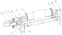
Fig. 1 is a schematic view of the overall structure of the present invention;
fig. 2 is a side view of the present invention;
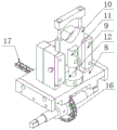
fig. 3 is a schematic perspective view of the adjusting mechanism of the present invention;
fig. 4 is a front view of the adjustment mechanism of the present invention;
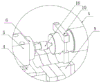
fig. 5 is an enlarged view of the structure of the portion a of fig. 1 according to the present invention.
Description of reference numerals:
the grinding machine comprises a machine frame 1, a support frame 2, a machine body 3 guide rail 3, a sliding plate 4, a power head 5, a main shaft 6, a motor 7, a sliding plate seat 8, a fixed frame 9, a support seat 10, an adjusting screw rod 11, an adjusting nut 12, an air cylinder 13, a tailstock nut 14, a tip screw rod 15, a sprocket wheel 16, a chain 17 and a grinding head 18.
Detailed Description
In order to make the technical solution of the present invention better understood by those skilled in the art, the present invention will be further described in detail with reference to the accompanying drawings.
The utility model provides a center hole precision grinding machine as shown in figures 1-5, which comprises a frame 1, wherein one side of the top of the frame 1 is fixedly connected with a support frame 2, the top of the support frame 2 is provided with a grinding mechanism, the top of the frame 1 is provided with a lathe bed guide rail 3, and the top of the lathe bed guide rail 3 is provided with an adjusting mechanism;
the grinding mechanism comprises a sliding plate 4, the sliding plate 4 is arranged at the top of a support frame 2, the sliding plate 4 is connected with the support frame 2 in a sliding manner, the top of the sliding plate 4 is fixedly connected with a power head 5, one side of the power head 5 is provided with a main shaft 6, the main shaft 6 penetrates through the power head 5 and is rotatably connected with the power head 5 through a bearing, one end of the main shaft 6 is provided with a grinding head 18, the bottom of the sliding plate 4 is fixedly connected with a motor 7, and an output shaft of the motor 7 is connected with the other end;
the adjusting mechanism comprises a sliding plate seat 8, the sliding plate seat 8 is arranged at the top of the lathe bed guide rail 3, the sliding plate seat 8 is connected with the lathe bed guide rail 3 in a sliding manner, and a supporting assembly is arranged at the top of the sliding plate seat 8;
the supporting component comprises a fixing frame 9, the fixing frame 9 is arranged at the top of the sliding plate seat 8, the fixing frame 9 is fixedly connected with the sliding plate seat 8, a supporting seat 10 is arranged at the top of the fixing frame 9, the supporting seat 10 extends into the fixing frame 9, the supporting seat 10 is connected with the fixing frame 9 in a sliding mode, an adjusting screw rod 11 is arranged at the bottom of the supporting seat 10, the adjusting screw rod 11 is fixedly connected with the supporting seat 10, an adjusting nut 12 is sleeved outside the adjusting screw rod 11, the adjusting nut 12 is in threaded connection with the adjusting screw rod 11, the adjusting nut 12 is arranged at the top of the sliding plate seat 8, and the adjusting nut 12 is rotatably connected with the sliding plate seat 8.
Further, in the above technical solution, the support seat 10 includes an upper support plate and a lower support plate, and the upper support plate and the lower support plate are fixedly connected by screws.
Furthermore, in the above technical solution, the number of the support assemblies is two, and the other support assembly is arranged on one side of the support frame 2 and is fixedly connected with the frame 1.
Further, in the above technical scheme, a cylinder 13 is arranged on one side of the support frame 2, which is far away from the rack 1, the cylinder 13 is fixedly connected with the support frame 2, and an output end of the cylinder 13 is in transmission connection with the sliding plate 4.
Further, in the above technical solution, a tailstock nut 14 is disposed on a side of the frame 1 away from the support frame 2, the tailstock nut 14 is fixedly connected to the frame 1, a tip screw 15 is disposed on a side of the tailstock nut 14, the tip screw 15 penetrates through the tailstock nut 14 and is in threaded connection with the tailstock nut 14, and the tip screw 15 corresponds to the grinding head 18.
Further, in the above technical solution, the grinding head 18 is made of cemented carbide material.
Further, in the above technical scheme, the number of the bed body guide rails 3 is two, two chain wheels 16 are fixedly connected between the two bed body guide rails 3, the two chain wheels 16 are respectively provided with two sides of the sliding plate seat 8, a chain 17 is arranged between the two chain wheels 16, the chain 17 is meshed with the two chain wheels 16, and two ends of the chain 17 are respectively fixedly connected with two ends of the sliding plate seat 8.
The implementation mode is specifically as follows: when the utility model is used, the knife roll type parts to be ground are firstly placed at the top of the frame 1, the rotating shafts at the two ends of the parts are fixed through the supporting seat 10, the rotating shafts are clamped through the upper supporting plate and the lower supporting plate, then the upper supporting plate and the lower supporting plate are fixed through screws, the rotating shafts with different outer diameters can be fixed through the design of the upper supporting plate and the lower supporting plate, thereby the parts are fixed, through the arrangement of the sliding plate seat 8, the chain wheel 16 is rotated to drive the chain 17 to move along the direction between the two chain wheels 16, so that the chain wheel 16 drives the sliding plate seat 8 fixedly connected with the chain wheel 16 to move, thereby the supporting component on the sliding plate seat 8 is close to another supporting component, thereby the utility model can be suitable for the parts with different lengths, through rotating the adjusting nut 12, the adjusting screw rod 11 is driven to move up and down, the height of the supporting seat 10 can be adjusted according to the outer diameter of the rotating shaft, so that the center of the part fixed by the supporting seat 10 coincides with the center of the grinding head 18, the utility model can be suitable for rotating shafts with different outer diameters, then the top screw 15 is rotated, the top screw 15 is moved to the other side of the rotating shaft and then abuts against the rotating shaft, thereby fixing the part and avoiding the axial sliding of the part, then the motor 7 is started, the output shaft of the motor 7 drives the main shaft 6 to rotate, thereby driving the grinding head 18 at one end of the main shaft 6 to rotate, then the cylinder 13 is started, the output end of the cylinder 13 pushes the sliding plate 4 to move, thereby driving the power head 5 at the top of the sliding plate 4 to move, further driving the power head 5 to drive the main shaft 6 to move, the main shaft 6 drives the grinding head 18 to rotate and simultaneously drives the grinding head 18 to do feed motion, the shaft with the same outer diameter can only be processed, and the applicability is poor.
While certain exemplary embodiments of the present invention have been described above by way of illustration only, it will be apparent to those of ordinary skill in the art that the described embodiments may be modified in various different ways without departing from the spirit and scope of the present invention. Accordingly, the drawings and description are illustrative in nature and should not be construed as limiting the scope of the invention.
Claims (7)
1. A precision grinding machine for center holes comprises a machine frame (1) and is characterized in that: a support frame (2) is fixedly connected to one side of the top of the rack (1), a grinding mechanism is arranged at the top of the support frame (2), a lathe bed guide rail (3) is arranged at the top of the rack (1), and an adjusting mechanism is arranged at the top of the lathe bed guide rail (3);
the grinding mechanism comprises a sliding plate (4), the sliding plate (4) is arranged at the top of the support frame (2), the sliding plate (4) is connected with the support frame (2) in a sliding mode, a power head (5) is fixedly connected to the top of the sliding plate (4), a main shaft (6) is arranged on one side of the power head (5), the main shaft (6) penetrates through the power head (5) and is rotatably connected with the power head (5) through a bearing, a grinding head (18) is installed at one end of the main shaft (6), a motor (7) is fixedly connected to the bottom of the sliding plate (4), and an output shaft of the motor (7) is connected with the other end of the;
the adjusting mechanism comprises a sliding plate seat (8), the sliding plate seat (8) is arranged at the top of the lathe bed guide rail (3), the sliding plate seat (8) is connected with the lathe bed guide rail (3) in a sliding mode, and a supporting assembly is arranged at the top of the sliding plate seat (8);
the supporting component comprises a fixing frame (9), the fixing frame (9) is arranged at the top of the sliding plate seat (8), the fixing frame (9) is fixedly connected with the sliding plate seat (8), a supporting seat (10) is arranged at the top of the fixing frame (9), the supporting seat (10) extends into the fixing frame (9), the supporting seat (10) is slidably connected with the fixing frame (9), an adjusting screw rod (11) is arranged at the bottom of the supporting seat (10), the adjusting screw rod (11) is fixedly connected with the supporting seat (10), an adjusting nut (12) is sleeved outside the adjusting screw rod (11), the adjusting nut (12) is in threaded connection with the adjusting screw rod (11), the adjusting nut (12) is arranged at the top of the sliding plate seat (8), and the adjusting nut (12) is rotatably connected with the sliding plate seat (8).
2. A precision grinding machine for center holes according to claim 1, wherein: the supporting seat (10) comprises an upper supporting plate and a lower supporting plate, and the upper supporting plate is fixedly connected with the lower supporting plate through screws.
3. A precision grinding machine for center holes according to claim 1, wherein: the number of the supporting components is two, the other supporting component is arranged on one side of the supporting frame (2), and the supporting components are fixedly connected with the rack (1).
4. A precision grinding machine for center holes according to claim 1, wherein: the air cylinder (13) is arranged on one side, away from the rack (1), of the support frame (2), the air cylinder (13) is fixedly connected with the support frame (2), and the output end of the air cylinder (13) is in transmission connection with the sliding plate (4).
5. A precision grinding machine for center holes according to claim 1, wherein: the grinding head is characterized in that a tailstock nut (14) is arranged on one side, away from the support frame (2), of the frame (1), the tailstock nut (14) is fixedly connected with the frame (1), a tip screw (15) is arranged on one side of the tailstock nut (14), the tip screw (15) penetrates through the tailstock nut (14) and is in threaded connection with the tailstock nut (14), and the tip screw (15) corresponds to the grinding head (18).
6. A precision grinding machine for center holes according to claim 1, wherein: the grinding head (18) is made of a cemented carbide material.
7. A precision grinding machine for center holes according to claim 1, wherein: the number of the lathe bed guide rails (3) is two, two chain wheels (16) are fixedly connected between the lathe bed guide rails (3), the two chain wheels (16) are respectively arranged on two sides of the sliding plate seat (8), a chain (17) is arranged between the two chain wheels (16), the chain (17) is meshed with the two chain wheels (16), and two ends of the chain (17) are respectively fixedly connected with two ends of the sliding plate seat (8).
Priority Applications (1)
| Application Number | Priority Date | Filing Date | Title |
|---|---|---|---|
| CN202021830715.7U CN213054295U (en) | 2020-08-28 | 2020-08-28 | Precision grinding machine for center hole |
Applications Claiming Priority (1)
| Application Number | Priority Date | Filing Date | Title |
|---|---|---|---|
| CN202021830715.7U CN213054295U (en) | 2020-08-28 | 2020-08-28 | Precision grinding machine for center hole |
Publications (1)
| Publication Number | Publication Date |
|---|---|
| CN213054295U true CN213054295U (en) | 2021-04-27 |
Family
ID=75554874
Family Applications (1)
| Application Number | Title | Priority Date | Filing Date |
|---|---|---|---|
| CN202021830715.7U Active CN213054295U (en) | 2020-08-28 | 2020-08-28 | Precision grinding machine for center hole |
Country Status (1)
| Country | Link |
|---|---|
| CN (1) | CN213054295U (en) |
-
2020
- 2020-08-28 CN CN202021830715.7U patent/CN213054295U/en active Active
Similar Documents
| Publication | Publication Date | Title |
|---|---|---|
| CN210173144U (en) | Slender rod cylindrical grinding machine | |
| CN201324992Y (en) | Double-raceway one-time grinding number control machine tool for high-speed railway bearing outer ring | |
| CN107363691B (en) | Method for realizing simultaneous grinding of two end faces of self-made grinding machine | |
| CN106425488B (en) | A kind of wheel rim process equipment of wheel hub | |
| CN201960139U (en) | Centerless lathe adopting electric spindle and realizing automatic centering of cylindrical rod and pipe material | |
| CN113059440A (en) | Cutter grinding machine | |
| CN115890395A (en) | Glass edge grinding machine capable of accurately feeding | |
| CN101433984B (en) | Centreless ball screw grinding machine and grinding technique thereof | |
| CN204935343U (en) | Roller sphere mill overcharge is put | |
| CN211841257U (en) | Center hole grinding machine for precision grinding | |
| CN213054295U (en) | Precision grinding machine for center hole | |
| CN217122676U (en) | Bearing roller end surface grinding machine | |
| CN216883179U (en) | Head walking type follow-up grinding machine suitable for processing inner and outer curves | |
| CN115741263A (en) | Multifunctional high-speed silicon carbide rolling and grinding machine | |
| CN115091349A (en) | Steel pipe chiba wheel burnishing device | |
| CN113977423A (en) | Numerical control vertical double-grinding head multifunctional grinding machine | |
| CN213196472U (en) | Horizontal compound grinding machine | |
| CN212947039U (en) | Precision groove grinding machine tool convenient for feeding and loading | |
| CN202572033U (en) | Internal circular grinding machine | |
| CN111098211A (en) | Vertical grinding and super-integrating machine for spherical basal plane of conical roller | |
| CN214322966U (en) | Hydraulic cylinder polishing equipment | |
| CN215201046U (en) | Spindle coping device | |
| CN210115682U (en) | Machining cutting equipment | |
| CN211277853U (en) | Vertical grinding and super-integrating machine for spherical basal plane of conical roller | |
| CN110549198A (en) | Internal spherical surface grinding machine |
Legal Events
| Date | Code | Title | Description |
|---|---|---|---|
| GR01 | Patent grant | ||
| GR01 | Patent grant |