CN115091349A - Steel pipe chiba wheel burnishing device - Google Patents
Steel pipe chiba wheel burnishing device Download PDFInfo
- Publication number
- CN115091349A CN115091349A CN202210922971.6A CN202210922971A CN115091349A CN 115091349 A CN115091349 A CN 115091349A CN 202210922971 A CN202210922971 A CN 202210922971A CN 115091349 A CN115091349 A CN 115091349A
- Authority
- CN
- China
- Prior art keywords
- steel pipe
- polishing
- straightening
- thousand
- supporting rollers
- Prior art date
- Legal status (The legal status is an assumption and is not a legal conclusion. Google has not performed a legal analysis and makes no representation as to the accuracy of the status listed.)
- Granted
Links
- 229910000831 Steel Inorganic materials 0.000 title claims abstract description 90
- 239000010959 steel Substances 0.000 title claims abstract description 90
- LFYJSSARVMHQJB-QIXNEVBVSA-N bakuchiol Chemical compound CC(C)=CCC[C@@](C)(C=C)\C=C\C1=CC=C(O)C=C1 LFYJSSARVMHQJB-QIXNEVBVSA-N 0.000 title claims description 7
- 238000005498 polishing Methods 0.000 claims abstract description 53
- 230000005540 biological transmission Effects 0.000 claims description 2
- 230000008878 coupling Effects 0.000 claims 1
- 238000010168 coupling process Methods 0.000 claims 1
- 238000005859 coupling reaction Methods 0.000 claims 1
- 230000000694 effects Effects 0.000 description 6
- 238000012986 modification Methods 0.000 description 2
- 230000004048 modification Effects 0.000 description 2
- 230000000149 penetrating effect Effects 0.000 description 2
- 239000004576 sand Substances 0.000 description 2
- 229910001369 Brass Inorganic materials 0.000 description 1
- 239000003082 abrasive agent Substances 0.000 description 1
- PNEYBMLMFCGWSK-UHFFFAOYSA-N aluminium oxide Inorganic materials [O-2].[O-2].[O-2].[Al+3].[Al+3] PNEYBMLMFCGWSK-UHFFFAOYSA-N 0.000 description 1
- 238000013459 approach Methods 0.000 description 1
- 230000004323 axial length Effects 0.000 description 1
- 230000009286 beneficial effect Effects 0.000 description 1
- 239000010951 brass Substances 0.000 description 1
- 230000007547 defect Effects 0.000 description 1
- 239000004744 fabric Substances 0.000 description 1
- 239000003292 glue Substances 0.000 description 1
- 238000010030 laminating Methods 0.000 description 1
- 239000000463 material Substances 0.000 description 1
- 239000011347 resin Substances 0.000 description 1
- 229920005989 resin Polymers 0.000 description 1
- 238000007711 solidification Methods 0.000 description 1
- 230000008023 solidification Effects 0.000 description 1
- 229910001220 stainless steel Inorganic materials 0.000 description 1
- 239000010935 stainless steel Substances 0.000 description 1
- 238000006467 substitution reaction Methods 0.000 description 1
- 230000003746 surface roughness Effects 0.000 description 1
- 238000003466 welding Methods 0.000 description 1
Images


Classifications
-
- B—PERFORMING OPERATIONS; TRANSPORTING
- B24—GRINDING; POLISHING
- B24B—MACHINES, DEVICES, OR PROCESSES FOR GRINDING OR POLISHING; DRESSING OR CONDITIONING OF ABRADING SURFACES; FEEDING OF GRINDING, POLISHING, OR LAPPING AGENTS
- B24B29/00—Machines or devices for polishing surfaces on work by means of tools made of soft or flexible material with or without the application of solid or liquid polishing agents
- B24B29/02—Machines or devices for polishing surfaces on work by means of tools made of soft or flexible material with or without the application of solid or liquid polishing agents designed for particular workpieces
- B24B29/06—Machines or devices for polishing surfaces on work by means of tools made of soft or flexible material with or without the application of solid or liquid polishing agents designed for particular workpieces for elongated workpieces having uniform cross-section in one main direction
- B24B29/08—Machines or devices for polishing surfaces on work by means of tools made of soft or flexible material with or without the application of solid or liquid polishing agents designed for particular workpieces for elongated workpieces having uniform cross-section in one main direction the cross-section being circular, e.g. tubes, wires, needles
-
- B—PERFORMING OPERATIONS; TRANSPORTING
- B21—MECHANICAL METAL-WORKING WITHOUT ESSENTIALLY REMOVING MATERIAL; PUNCHING METAL
- B21D—WORKING OR PROCESSING OF SHEET METAL OR METAL TUBES, RODS OR PROFILES WITHOUT ESSENTIALLY REMOVING MATERIAL; PUNCHING METAL
- B21D3/00—Straightening or restoring form of metal rods, metal tubes, metal profiles, or specific articles made therefrom, whether or not in combination with sheet metal parts
- B21D3/14—Recontouring
-
- B—PERFORMING OPERATIONS; TRANSPORTING
- B24—GRINDING; POLISHING
- B24B—MACHINES, DEVICES, OR PROCESSES FOR GRINDING OR POLISHING; DRESSING OR CONDITIONING OF ABRADING SURFACES; FEEDING OF GRINDING, POLISHING, OR LAPPING AGENTS
- B24B41/00—Component parts such as frames, beds, carriages, headstocks
- B24B41/02—Frames; Beds; Carriages
-
- B—PERFORMING OPERATIONS; TRANSPORTING
- B24—GRINDING; POLISHING
- B24B—MACHINES, DEVICES, OR PROCESSES FOR GRINDING OR POLISHING; DRESSING OR CONDITIONING OF ABRADING SURFACES; FEEDING OF GRINDING, POLISHING, OR LAPPING AGENTS
- B24B41/00—Component parts such as frames, beds, carriages, headstocks
- B24B41/06—Work supports, e.g. adjustable steadies
-
- B—PERFORMING OPERATIONS; TRANSPORTING
- B24—GRINDING; POLISHING
- B24B—MACHINES, DEVICES, OR PROCESSES FOR GRINDING OR POLISHING; DRESSING OR CONDITIONING OF ABRADING SURFACES; FEEDING OF GRINDING, POLISHING, OR LAPPING AGENTS
- B24B47/00—Drives or gearings; Equipment therefor
- B24B47/20—Drives or gearings; Equipment therefor relating to feed movement
Landscapes
- Engineering & Computer Science (AREA)
- Mechanical Engineering (AREA)
- Grinding Of Cylindrical And Plane Surfaces (AREA)
Abstract
The invention discloses a polishing device for a steel pipe thousand-blade wheel, which belongs to the technical field of polishing devices and comprises a base; the two supporting rollers are horizontally and rotatably connected to the vertical plate of the base, the axial directions of the supporting rollers are consistent with the length direction of the base, and the two supporting rollers are driven by the two stepping motors to synchronously rotate respectively; the movable frame consists of two upright posts and a cross rod; a polishing unit; a drive unit; and a straightening unit. Through the setting of alignment unit, can straighten the steel pipe, make the circularity (or cylindricity) of steel pipe obtain improvement to a certain extent, when avoiding the steel pipe rotatory, steel pipe local position does not produce the blind area of polishing and polishing with thousand impeller contact, polishing precision and efficiency have been promoted, it comprises first gear to set up the drive unit in addition, the second gear, the lead screw, the screw box, movable block, so through the rotation of backing roll, make thousand impeller can remove in step, realize the autofeed, in order to promote automatic level.
Description
Technical Field
The invention relates to the technical field of polishing devices, in particular to a polishing device for a thousand impellers of a steel pipe.
Background
After the steel pipe is machined, the surface roughness is large, so that the pipe wall of the machined steel pipe needs to be polished, the steel pipe is polished mainly by a polishing device at present, a thousand-blade wheel and a chuck-type blade wheel are mounted on polishing equipment, the polishing equipment belongs to one kind of coated abrasive tools, and each product is formed by bonding hundreds of gauze pieces, so that the product is famous. The gauze is prepared by taking alumina as an abrasive material and a base material as a cloth base through an assembly line, and then is formed by laminating a gauze layer and a full resin. The upper and lower open groove of chuck fixes sand blade between the chuck from top to bottom, and the both ends of the inboard side of sand blade set up L shape buckle groove and clamping ring respectively, clamping ring and buckle groove fixed connection, the clamping ring is in the same place through glue solution and buckle groove solidification bonding, forms the flap wheel, and the flap wheel divide into straight flute and U type notch two kinds, and is rotatory through motor drive flap wheel, and then makes the flap wheel polish the pipe wall of steel pipe.
When the roundness (or cylindricity) of the steel pipe is poor, the surface of the steel pipe may not be in contact with the surface of the impeller at a local position, so that the local part of the steel pipe is not polished, and the polishing and grinding effect of the steel pipe is further affected.
Disclosure of Invention
The invention aims to overcome the defects of the prior art and provides a polishing device for a steel pipe with a thousand-impeller, aiming at solving the technical problems that the roundness (or cylindricity) of a steel pipe influences the polishing effect when polishing is carried out in the prior art, and when the roundness (or cylindricity) of the steel pipe is poor, the surface of the steel pipe possibly has local positions which cannot contact the surface of the thousand-impeller, so that the local part of the steel pipe is not polished, and the polishing and grinding effect of the steel pipe is influenced, the invention provides the following technical scheme:
the present invention provides: a steel pipe chiba wheel burnishing device includes:
a base;
the two supporting rollers are horizontally and rotatably connected to the vertical plate of the base, the axial directions of the supporting rollers are consistent with the length direction of the base, and the two supporting rollers are driven by two stepping motors to synchronously rotate respectively;
the movable frame consists of two upright posts and a cross bar;
the polishing unit is arranged on the cross bar and is positioned right above the space between the two supporting rollers;
the driving unit is used for driving the moving frame to move along the length direction of the base;
and the straightening unit is used for straightening the steel pipes placed on the two supporting rollers and can be matched with the two supporting rollers to radially limit the steel pipes.
In the above polishing device for the steel pipe thousand-blade wheel, the polishing unit includes:
the polishing motor is arranged on the cross rod;
the impeller is coaxially connected with a motor shaft of the polishing motor, and the axial direction of the impeller is parallel to the axial direction of the supporting roller.
In the above-mentioned steel pipe chiba polishing device, the driving unit includes:
the two first gears are respectively and coaxially connected to the two supporting rollers;
the two screw rods are respectively and horizontally connected to two opposite sides of the vertical plate in a rotating manner;
the two second gears are respectively and coaxially connected to the two screw rods, and the first gear and the second gear are correspondingly in meshing transmission;
the two screw nut sleeves are respectively sleeved on the two screw rods in a threaded manner;
and the two moving blocks are respectively sleeved on the two nut sleeves, and the two upright posts are respectively and vertically and fixedly connected to the two moving blocks.
In the above polishing device for the steel pipe thousand-bladed wheel, the two vertical plates are respectively connected with a limiting disc in a horizontal rotating manner, and the two limiting discs are used for axially limiting the steel pipe.
In the foregoing polishing apparatus for steel pipe thousand-blade wheels, the straightening unit includes:
the two straightening rods are respectively connected to the two upright columns;
and the two arc-shaped straightening tiles are respectively connected to the opposite ends of the two straightening rods, and the inner arc surfaces of the two straightening tiles are in sliding contact with the pipe wall of the steel pipe.
Compared with the prior art, the invention has the beneficial effects that: through the setting of alignment unit, can straighten the steel pipe, make the circularity (or cylindricity) of steel pipe obtain improvement to a certain extent, when avoiding the steel pipe rotatory, steel pipe local position does not produce the blind area of polishing and polishing with the contact of chiba wheel, polishing precision and efficiency have been promoted, it comprises first gear to set up the drive unit in addition, the second gear, the lead screw, the screw box, the movable block, etc. through the rotation of backing roll like this, make chiba wheel can remove in step, realize the automatic feed, in order to promote automatic level, need not additionally to set up power element and controlling means, the simplified operation, and the cost is reduced, through setting up the alignment tile, can enough centre gripping steel pipe, in order to produce radial spacing to the steel pipe, in addition because alignment tile concave surface is less with steel pipe surface friction coefficient, and then can not influence the rotation of steel pipe, reduce the steel pipe wearing and tearing.
Drawings
The accompanying drawings, which are included to provide a further understanding of the invention and are incorporated in and constitute a part of this specification, illustrate embodiments of the invention and together with the description serve to explain the principles of the invention and not to limit the invention. In the drawings:
FIG. 1 is a schematic view of an assembly structure of a polishing device for steel pipe thousand-blade wheels according to the present invention;
FIG. 2 is an enlarged view of a portion of the structure at A in FIG. 1;
FIG. 3 is a schematic side view of an assembly structure of a polishing device for steel pipe millennia according to the present invention;
FIG. 4 is a schematic view of another angle of the assembly structure of the polishing device for steel pipe thousand-bladed wheels according to the present invention;
fig. 5 is an exploded schematic view of the structure of fig. 4.
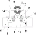
In the figure: 1-vertical plate, 2-stepping motor, 3-base, 4-inclined groove, 5-straight groove, 6-fixed seat, 7-cross bar, 8-vane wheel, 9-polishing motor, 10-steel pipe, 11-second gear, 12-limiting disc, 13-first gear, 14-upright column, 15-straightening tile, 16-straightening rod, 17-ball bearing, 18-screw rod, 19-moving block, 20-supporting roller and 21-screw sleeve.
Detailed Description
The preferred embodiments of the present invention will be described in conjunction with the accompanying drawings, and it will be understood that they are described herein for the purpose of illustration and explanation and not limitation.
Examples
As shown in fig. 1 to 5, the present embodiment provides a technical solution: a polishing device for steel pipe thousand-impeller comprises a base 3, two vertical plates 1 are vertically and fixedly connected to two ends of the length direction of the base 3, two supporting rollers 20 are horizontally and rotatably connected to the two vertical plates 1 through a first pivot, the first pivot is suitable for a mounting bearing to be rotatably connected to the vertical plates 1, so that the supporting rollers 20 can rotate on the vertical plates 1, the two supporting rollers 20 are symmetrically arranged, the axial direction of the supporting rollers 20 is consistent with the length direction of the base 3, two stepping motors 2 are mounted on one vertical plate 1, the two supporting rollers 20 are respectively driven by the two stepping motors 2 to synchronously rotate, the rotating speed and the rotating direction of the two stepping motors 2 are controlled by a frequency converter or other controllers, the two stepping motors 2 are further ensured to synchronously rotate, the two supporting rollers 20 are further driven to synchronously rotate in the same direction, two transversely opposite sides of the two vertical plates 1 are jointly and horizontally and rotatably connected with a screw rod 18, two screw rods 18 respectively correspond to two sides of the base 3 in the width direction, the axial direction of the screw rods 18 is parallel to the length direction of the base 3, the two screw rods 18 are positioned outside two support rollers 20, or the two support rollers 20 are positioned between the two screw rods 18, a nut sleeve 21 is sleeved on each screw thread on each screw rod 18, a movable block 19 is sleeved on each nut sleeve 21, as shown in fig. 2, a slot for inserting the nut sleeve 21 is formed in each movable block 19, so that the nut sleeves 21 are connected with the movable blocks 19, a stand column 14 is vertically and fixedly connected to each of the two movable blocks 19, the upper ends of the two stand columns 14 are positioned above the support rollers 20 and are jointly and horizontally connected with a cross rod 7, a motor mounting plate is integrally formed on the cross rod 7, a polishing motor 9 is horizontally mounted on the motor mounting plate, the polishing motor 9 is powered by an external power supply module, and the polishing motor 9 penetrates out of the motor shaft mounting plate, and one end of the motor shaft penetrating through the motor mounting plate is coaxially connected with a thousand-blade wheel 8, the thousand-blade wheel 8 can be mounted at the end part of the motor shaft of the polishing motor 9 by welding, screw connection and other modes, the polishing motor 9 is electrified to rotate and can drive the thousand-blade wheel 8 to rotate at a high speed, the rotating speed of the thousand-blade wheel 8 is not less than 600rpm, in addition, the axis of the thousand-blade wheel 8 is parallel to the length direction of the base 3, one ends of two supporting rollers 20 penetrate through the vertical plate 1 and are respectively sleeved with a first gear 13, one ends of two screw rods 18 are respectively sleeved with a second gear 11, the first gear 13 and the second gear 11 are in a meshing state, thus when the supporting rollers 20 rotate, the first gear 13 and the second gear 11 are synchronously driven to mesh and transmit, and then the two screw rods 18 can be driven to rotate, when the screw rods 18 rotate, the upright posts 14 and the cross rods 7 are driven to horizontally move, so that the thousand-blade wheel can horizontally move, when the device works, the steel pipe 10 is placed between the two supporting rollers 20 in a flat manner, the steel pipe 10 can be supported by the aid of the two supporting rollers 20, the steel pipe 10 can be centered automatically, or the highest point of the outer edge of the pipe wall of the steel pipe 10 is in contact with the lowest point of the outer edge of the vane wheel and keeps a certain abutting force, the other two upright posts 14 are respectively and horizontally provided with the straightening rods 16 in a penetrating manner, the straightening rods 16 can horizontally and freely slide on the upright posts 14, the opposite ends of the other two straightening rods 16 or the ends corresponding to the inner sides of the width direction of the base 3 are respectively connected with the straightening shoes 15, the outer contours of the straightening shoes 15 are arc-shaped, the centers of the arc-shaped circles are coaxial with the axis of the steel pipe 10, after the straightening shoes 15 are in contact with the pipe wall of the steel pipe 10, in addition, the straightening shoes 15 are made of brass or stainless steel, and thus the friction resistance between the straightening shoes 15 and the pipe wall of the steel pipe 10 is smaller, so that the straightening tile 15 does not affect the rotation of the steel pipe when clamping the pipe wall of the steel pipe, in addition, one end of the straightening rod 16 far away from the straightening tile 15 is vertically connected with a second pivot, a ball bearing 17 is installed at the lower end of the second pivot, two sides of the width direction of the base 3 are respectively provided with a fixed seat 6, the length direction of the fixed seat 6 is parallel to the length direction of the base 3, in addition, the top of the fixed seat 6 is provided with a special-shaped groove, the special-shaped groove comprises two inclined grooves 4 and a straight groove 5, the two inclined grooves 4 respectively correspond to the two ends of the length direction of the base 3, the length direction of the straight groove 5 is parallel to the length direction of the base 3, in addition, the length of the straight groove 5 is not less than the length of the steel pipe to be polished, one end of the inclined groove 4 is communicated with the straight groove 5, the other end of the inclined groove 4 extends towards the outer side of the width direction of the base 3 in an inclined manner, the ball bearing 17 is clamped in the special-shaped groove, in addition, the outer diameter of the ball bearing is matched with the width of the special-shaped groove, the ball bearing 17 can roll on the straight groove 5 and the inclined groove 4, after the steel pipe is positioned, the two support rollers 20 are driven by the two stepping motors 2 to rotate, the steel pipe can also rotate through the friction resistance between the support rollers and the steel pipe, the steel pipe can rotate along one direction due to the consistent steering of the two support rollers, the other two support rollers drive the second gear 11 to rotate by the first gear 13 and can drive the two lead screws 18 to rotate when rotating, so that the nut sleeve 21 can drive the movable block 19 to horizontally move, meanwhile, the polishing motor is electrified to rotate and enables the flap wheel to rotate, further the flap wheel can rotate and polish the pipe wall of the steel pipe, and the steel pipe synchronously rotates, so that the flap wheel can polish all parts of the steel pipe, and in addition, the two movable blocks drive the upright posts and the cross rod 7 to horizontally move, the flap wheel moves along the axial direction of the steel pipe to polish and polish the pipe wall in the whole length direction of the steel pipe, when the upright post moves horizontally, the straightening rod is driven to move horizontally, in addition, the ball bearing 17 rotates in the special-shaped groove, so that the ball bearing 17 can enter the straight groove from the inclined groove 4, correspondingly, the straightening rod can be driven to move towards the inner side direction of the width direction of the base 3, the inner arc surfaces of the two straightening tiles 15 embrace the steel pipe without influencing the rotation of the steel pipe, and the straightening tiles generate a resisting force on the convex parts of the pipe wall along with the movement of the upright post, so that the pipe wall can be corrected by the straightening tiles, the roundness (or cylindricity) of the steel pipe can be corrected, the roundness (or cylindricity) of the steel pipe is improved as much as possible, and when the flap wheel polishes and polishes the steel pipe, the phenomenon that the local part of the surface of the steel pipe is not polished and polished can not be generated, the polishing and grinding efficiency and precision are improved, after polishing is finished, namely after the moving block moves to the axial outer side of the steel pipe, the ball bearing 17 rotates from the straight groove 5 to the inclined groove 4, so that the straightening tile 15 can be far away from the steel pipe, and further the unloading operation of the steel pipe is convenient, meanwhile, during polishing, the ball bearing enters the straight groove from the inclined groove, so that the straightening tile gradually approaches the steel pipe and clamps the steel pipe, in addition, two limiting discs 12 are rotationally connected to the two vertical plates through mounting a third pivot, the third pivot is also suitable for mounting the bearing to be rotationally connected to the vertical plates, the transverse distance between the two limiting discs 12 is matched with the axial length dimension of the steel pipe, after the steel pipe is placed on the two supporting rollers, the steel pipe can be axially limited through the two limiting discs 12, and when polishing and grinding is avoided, the steel pipe generates movement to influence the polishing and grinding effect, in this embodiment, in order to improve the polishing effect on the surface of the steel pipe, the nominal diameter of the first gear can be set to be at most half of the nominal diameter of the second gear, so that the rotation ratio of the first gear to the second gear can be optimized, and the translation speed of the flap wheel is slowed down, so that the contact time of the flap wheel to each part of the surface of the steel pipe is increased, and the polishing and grinding effect is improved.
Finally, it should be noted that: although the present invention has been described in detail with reference to the foregoing embodiments, those skilled in the art will understand that various changes, modifications and substitutions can be made without departing from the spirit and scope of the invention as defined by the appended claims. Any modification, equivalent replacement, or improvement made within the spirit and principle of the present invention should be included in the protection scope of the present invention.
Claims (5)
1. The utility model provides a steel pipe chiba wheel burnishing device which characterized in that includes:
a base (3);
the two supporting rollers (20) are horizontally and rotatably connected to the vertical plate (1) of the base (3), the axial directions of the supporting rollers (20) are consistent with the length direction of the base (3), and the two supporting rollers (20) are driven by the two stepping motors (2) to synchronously rotate respectively;
the movable frame consists of two upright posts (14) and a cross bar (7);
the polishing unit is arranged on the cross rod (7) and is positioned right above the space between the two supporting rollers (20);
the driving unit is used for driving the moving frame to move along the length direction of the base (3);
the straightening unit is used for straightening the steel pipe (10) placed on the supporting rollers (20), and can be matched with the two supporting rollers (20) to radially limit the steel pipe (10).
2. The steel pipe thousand-blade wheel polishing device according to claim 1, wherein said polishing unit comprises:
the polishing motor (9) is arranged on the cross rod (7);
the thousand impeller (8), with the motor shaft coaxial coupling of polishing motor (9), thousand impeller (8) axial and backing roll (20) axial direction parallel.
3. The steel pipe thousand-blade wheel polishing device according to claim 1, wherein said driving unit comprises:
two first gears (13) respectively and coaxially connected to the two support rollers (20);
the two screw rods (18) are respectively and horizontally and rotatably connected to two opposite sides of the vertical plate (1);
the two second gears (11) are respectively and coaxially connected to the two screw rods (18), and the first gear (13) and the second gear (11) are correspondingly meshed for transmission;
the two nut sleeves (21) are respectively sleeved on the two screw rods (18) in a threaded manner;
the two moving blocks (19) are respectively sleeved on the two nut sleeves (21), and the two upright posts (14) are respectively and vertically fixedly connected to the two moving blocks (19).
4. The polishing device for the steel pipe thousand-impeller according to claim 1, characterized in that two vertical plates (1) are respectively connected with a limiting disc (12) in a horizontal rotation manner, and the two limiting discs (12) are used for limiting the steel pipe (10) in an axial direction.
5. The steel pipe thousand-blade wheel polishing device of claim 1, wherein the straightening unit comprises:
two straightening rods (16) respectively connected to the two upright posts (14);
the two arc-shaped straightening tiles (15) are respectively connected to the opposite ends of the two straightening rods (16), and the inner arc surfaces of the two straightening tiles (15) are in sliding contact with the pipe wall of the steel pipe (10).
Priority Applications (1)
| Application Number | Priority Date | Filing Date | Title |
|---|---|---|---|
| CN202210922971.6A CN115091349B (en) | 2022-08-02 | 2022-08-02 | Steel pipe kiloimpeller burnishing device |
Applications Claiming Priority (1)
| Application Number | Priority Date | Filing Date | Title |
|---|---|---|---|
| CN202210922971.6A CN115091349B (en) | 2022-08-02 | 2022-08-02 | Steel pipe kiloimpeller burnishing device |
Publications (2)
| Publication Number | Publication Date |
|---|---|
| CN115091349A true CN115091349A (en) | 2022-09-23 |
| CN115091349B CN115091349B (en) | 2024-03-26 |
Family
ID=83301472
Family Applications (1)
| Application Number | Title | Priority Date | Filing Date |
|---|---|---|---|
| CN202210922971.6A Active CN115091349B (en) | 2022-08-02 | 2022-08-02 | Steel pipe kiloimpeller burnishing device |
Country Status (1)
| Country | Link |
|---|---|
| CN (1) | CN115091349B (en) |
Cited By (1)
| Publication number | Priority date | Publication date | Assignee | Title |
|---|---|---|---|---|
| CN115365972A (en) * | 2022-10-25 | 2022-11-22 | 常熟市长江不锈钢材料有限公司 | Steel strip surface cleaning device and using method thereof |
Citations (10)
| Publication number | Priority date | Publication date | Assignee | Title |
|---|---|---|---|---|
| KR20040002753A (en) * | 2002-06-26 | 2004-01-07 | 심상배 | Bowling ball resurfacing apparatus |
| CN202640110U (en) * | 2012-05-25 | 2013-01-02 | 江门市奥斯龙机械有限公司 | Automatic grinding and polishing machine |
| KR101489231B1 (en) * | 2014-06-24 | 2015-02-04 | 주식회사 성원공조 | The calibration device dry air duct |
| CN105415128A (en) * | 2015-12-03 | 2016-03-23 | 无锡市晨源建筑器材有限公司 | Welded steel tube polishing machine |
| CN107984370A (en) * | 2017-12-15 | 2018-05-04 | 济源市华中冶金机械有限公司 | A kind of cold roll polishing machine |
| CN209304310U (en) * | 2019-01-08 | 2019-08-27 | 无锡市精密钢管有限公司 | Synchronous deburring processing unit (plant) inside and outside a kind of tube body port |
| CN211439430U (en) * | 2019-12-28 | 2020-09-08 | 常州市武进良发机械传动件有限公司 | Automatic polishing mill for processing chain wheel |
| CN112454025A (en) * | 2020-11-09 | 2021-03-09 | 淄博职业学院 | Shaft rod straightening equipment for maintenance of electromechanical equipment and use method thereof |
| CN214771264U (en) * | 2021-05-28 | 2021-11-19 | 铜陵市大成轧辊有限责任公司 | Polishing equipment for roller production |
| CN216501647U (en) * | 2021-05-24 | 2022-05-13 | 青岛澳英电力设备有限公司 | Straightening mechanism for steel pipe pole |
-
2022
- 2022-08-02 CN CN202210922971.6A patent/CN115091349B/en active Active
Patent Citations (10)
| Publication number | Priority date | Publication date | Assignee | Title |
|---|---|---|---|---|
| KR20040002753A (en) * | 2002-06-26 | 2004-01-07 | 심상배 | Bowling ball resurfacing apparatus |
| CN202640110U (en) * | 2012-05-25 | 2013-01-02 | 江门市奥斯龙机械有限公司 | Automatic grinding and polishing machine |
| KR101489231B1 (en) * | 2014-06-24 | 2015-02-04 | 주식회사 성원공조 | The calibration device dry air duct |
| CN105415128A (en) * | 2015-12-03 | 2016-03-23 | 无锡市晨源建筑器材有限公司 | Welded steel tube polishing machine |
| CN107984370A (en) * | 2017-12-15 | 2018-05-04 | 济源市华中冶金机械有限公司 | A kind of cold roll polishing machine |
| CN209304310U (en) * | 2019-01-08 | 2019-08-27 | 无锡市精密钢管有限公司 | Synchronous deburring processing unit (plant) inside and outside a kind of tube body port |
| CN211439430U (en) * | 2019-12-28 | 2020-09-08 | 常州市武进良发机械传动件有限公司 | Automatic polishing mill for processing chain wheel |
| CN112454025A (en) * | 2020-11-09 | 2021-03-09 | 淄博职业学院 | Shaft rod straightening equipment for maintenance of electromechanical equipment and use method thereof |
| CN216501647U (en) * | 2021-05-24 | 2022-05-13 | 青岛澳英电力设备有限公司 | Straightening mechanism for steel pipe pole |
| CN214771264U (en) * | 2021-05-28 | 2021-11-19 | 铜陵市大成轧辊有限责任公司 | Polishing equipment for roller production |
Cited By (1)
| Publication number | Priority date | Publication date | Assignee | Title |
|---|---|---|---|---|
| CN115365972A (en) * | 2022-10-25 | 2022-11-22 | 常熟市长江不锈钢材料有限公司 | Steel strip surface cleaning device and using method thereof |
Also Published As
| Publication number | Publication date |
|---|---|
| CN115091349B (en) | 2024-03-26 |
Similar Documents
| Publication | Publication Date | Title |
|---|---|---|
| CN109604698B (en) | Multi-station numerical control double-side milling machine | |
| CN115091349A (en) | Steel pipe chiba wheel burnishing device | |
| CN107243786A (en) | A kind of grinding attachment of cylindric outer surface of workpiece | |
| CN110666695B (en) | Even coating device of grinding roller for plane polisher | |
| CN111055176A (en) | Device for grinding end face of gear | |
| CN201136118Y (en) | Abrasive band polisher for steel tubes | |
| CN117066983B (en) | Core shaft grinding machine for submerged halogen pump | |
| CN113977423A (en) | Numerical control vertical double-grinding head multifunctional grinding machine | |
| CN2750888Y (en) | Major diameter high precision glass polishing machine | |
| CN101642888B (en) | Grinding method and grinder of spherical surface of columnar workpiece | |
| CN116638430A (en) | Polishing device for machining | |
| CN108857836A (en) | A kind of polissoir for metal product | |
| CN215036097U (en) | Deburring device | |
| CN113319727B (en) | Polishing device for high-precision transmission screw machining and polishing method thereof | |
| CN112757146A (en) | Synchronous heat dissipation formula centrifugal grinder | |
| CN113103074A (en) | Manufacturing process of high-strength aluminum alloy automobile hub | |
| CN221088368U (en) | Automatic production device for cylindrical rollers | |
| CN213054295U (en) | Precision grinding machine for center hole | |
| CN221621823U (en) | Automatic polishing equipment | |
| CN218947368U (en) | Special-shaped clamping tool for surface grinding machine | |
| CN212470789U (en) | High-efficient equipment of polishing of bearing ring | |
| CN220162140U (en) | Polishing equipment | |
| CN220680273U (en) | Valve polishing machine | |
| CN219542546U (en) | Intelligent internal and external grinding machine for stainless steel pipes | |
| CN220029695U (en) | Automobile parts processing is with frock of polishing |
Legal Events
| Date | Code | Title | Description |
|---|---|---|---|
| PB01 | Publication | ||
| PB01 | Publication | ||
| SE01 | Entry into force of request for substantive examination | ||
| SE01 | Entry into force of request for substantive examination | ||
| GR01 | Patent grant | ||
| GR01 | Patent grant |