CN215201046U - Spindle coping device - Google Patents
Spindle coping device Download PDFInfo
- Publication number
- CN215201046U CN215201046U CN202121296851.7U CN202121296851U CN215201046U CN 215201046 U CN215201046 U CN 215201046U CN 202121296851 U CN202121296851 U CN 202121296851U CN 215201046 U CN215201046 U CN 215201046U
- Authority
- CN
- China
- Prior art keywords
- fixed
- motor
- rotary table
- spindle
- blind hole
- Prior art date
- Legal status (The legal status is an assumption and is not a legal conclusion. Google has not performed a legal analysis and makes no representation as to the accuracy of the status listed.)
- Active
Links
Images


Abstract
A spindle sharpening device comprises an L-shaped base formed by vertically and fixedly connecting a bottom plate and a back plate, a turntable which can be fixed and has an adjustable angle is arranged on the inner side surface of the back plate, a feeding sliding table is fixed on the turntable, a motor base which can reciprocate under the driving of the feeding sliding table is arranged on the feeding sliding table in a guiding mode, a motor support is fixed on the motor base, a spindle motor is fixed on the motor support, an output shaft of the spindle motor is connected with a grinding wheel rod, and a grinding wheel is fixed at the outer end of the grinding wheel rod. A starting switch and a travel switch with adjustable fixed positions are arranged on a connecting rod at one side of the feeding sliding table frame body, and a travel deflector rod is fixed on the motor base. The utility model can be used as an inner hole mill by combining numerical control and a common lathe, and the angle is adjustable to realize multi-angle use; the grinding machine is small in size, convenient and flexible, and is suitable for grinding most machining centers and main shafts of planer type milling machines.
Description
Technical Field
The utility model relates to the field of machinary, especially, relate to a main shaft coping ware for the coping processing of lathe main shaft.
Background
Machining centers are more and more popular in machining industry, but after the machining centers are used for a long time, the precision is lower and lower along with the reasons of abrasion and the like. The problems of a lead screw, a module and the like can only be solved in daily maintenance, the adjustment and the maintenance of the precision of the main shaft of the machine tool are generally realized by returning to an original factory after disassembly, grinding a cone again and replacing a bearing, and errors caused by secondary installation are always eliminated. The market also lacks equipment for specifically solving the problem.
Disclosure of Invention
The utility model aims at providing a main shaft coping ware solves the defect that is not enough to lathe main shaft coping professional equipment, just can realize the coping maintenance to the main shaft through this equipment, uses the producer to bring the convenience to the host computer.
The purpose of the utility model is realized with the following mode: the spindle coping device comprises an L-shaped base formed by vertically and fixedly connecting a bottom plate and a back plate, a turntable which can be adjusted in angle and fixed is arranged on the inner side surface of the back plate, a feeding sliding table is fixed on the turntable, a motor base which reciprocates under the driving of the feeding sliding table is arranged on the feeding sliding table in a guiding mode, a motor support is fixed on the motor base, a spindle motor is fixed on the motor support, an output shaft of the spindle motor is connected with a grinding wheel rod, and a grinding wheel is fixed at the outer end of the grinding wheel rod.
The structure of the feeding sliding table is as follows: feed the slip table and have preceding backup pad, even have the support body that connecting rod and guide rail constitute between the backup pad after, two guide rail are alternate and parallel to be in support body upper portion position, arrange two linear slide blocks on every guide rail, backup pad in the front, the middle part position that is in its width between the backup pad after and supports the lead screw of axial positioning through the bearing frame, the lead screw top spin has lead screw nut, lead screw nut fixes on the nut seat of cover on the lead screw, linear slide block on two guide rails supports and passes through screw fixed connection motor base, nut seat links together through screw and motor base, be fixed with the band pulley on the end that the lead screw stretches out the backup pad after, be fixed with feed motor in one side of support body, be fixed with the band pulley on feed motor's the output shaft, it has the hold-in range to articulate between band pulley on feed motor output shaft and the band pulley on the lead screw.
The fixed position of a starting point switch and a travel switch which are adjustable are arranged on a connecting rod at one side of the feeding sliding table frame body, a travel deflector rod is fixed on the motor base, and the other end of the travel deflector rod is positioned on a straight line where the starting point switch and the travel switch are positioned. The travel deflector rod moves along with the motor base, after the travel deflector rod touches the starting point switch or the travel switch, the starting point switch and the travel switch give control signals to the electric control part, and the electric control part controls the feeding sliding table to drive the spindle motor to move reversely, so that the purpose of reciprocating the spindle motor back and forth is achieved. The fixed position of the travel adjusting deflector rod on the motor base, the position of the starting point switch and the position of the travel switch on the feeding sliding table frame body can be adjusted, two limit positions of the starting point and the end point of the spindle motor can be adjusted, and the reciprocating travel of the spindle motor is also determined.
The connection mode of the turntable and the back plate is as follows: a backboard blind hole is formed in the middle of the backboard, a centering pin with a matched diameter is placed in the backboard blind hole, and a jacking pin pressure spring is supported between the bottom of the backboard blind hole and the centering pin; the center position below the turntable is provided with a turntable blind hole, the turntable blind hole is matched with the diameter of the centering pin, the turntable is attached to the upper surface of the back plate, the upper part of the centering pin is inserted into the turntable blind hole, 4 bolt through holes are distributed on the turntable and the concentric circle of the turntable blind hole at intervals, a section of T-shaped arc groove which is in the same concentric circle with the bolt through hole is arranged on the back plate corresponding to each turntable bolt through hole, a square bolt is inserted into the T-shaped arc groove, and a fixing nut is screwed after the screw rod part penetrates through the bolt through hole.
The utility model discloses a bottom plate is fixed on equipment, can angle regulation in order to aim at work piece machined surface through rotating the carousel, drives the positive and negative rotation of lead screw through feed motor and drives motor support and spindle motor reciprocating motion, and spindle motor drives the high-speed rotation of emery wheel and carries out abrasive machining to the work piece. The feeding motor can adopt a stepping motor, so that the spindle motor can do reciprocating motion in a circulating mode at an angle consistent with the taper of the machine tool spindle, and the inner cone can be sharpened.
The utility model can be used as an inner hole mill by combining numerical control and a common lathe, and the angle is adjustable to realize multi-angle use; the grinding machine is small in size, convenient and flexible, and is suitable for grinding most machining centers and main shafts of planer type milling machines.
Drawings
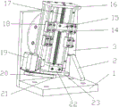
Fig. 1 is a schematic structural diagram of the present invention.
Fig. 2 is a schematic structural diagram of the present invention without a motor support and a spindle motor.
FIG. 3 is a front view of the connection of the backing plate to the turntable.
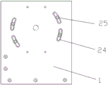
FIG. 4 is a top view of the connection of the backing plate to the turntable.
In the figure: 1-a bottom plate; 2-a support plate; 3-a back plate; 4-a turntable; 5-a feed slide; 6-start switch; 7-a travel switch; 8-a motor base; 9-stroke deflector rod; 10-a motor support; 11-a spindle motor; 12-grinding wheel bar; 13-grinding wheel; 14-a lead screw nut; 15-nut seats; 16-a front support plate; 17-a lead screw; 18-linear slide block; 19-a feed motor; 20-synchronous belt; 21-a pulley; 22-a bearing seat; 23-rear support plate; 24-T type arc groove; 25-square bolts; 26-a centering pin; 27-knock pin compression spring.
Detailed Description
Referring to fig. 1-4, there is an L-shaped base formed by vertically and fixedly connecting a base plate 1 and a back plate 3, and a support plate 2 is welded between the base plate 1 and the back plate 3 to increase rigidity. A backboard blind hole is formed in the middle of the backboard 3, a centering pin 26 with a matched diameter is placed in the backboard blind hole, and a jacking pin pressure spring 27 is supported between the bottom of the backboard blind hole and the centering pin 26; the rotary table is provided with a rotary table 4, a rotary table blind hole is arranged at the center position below the rotary table 4, the rotary table blind hole is matched with the diameter of a centering pin 26, the rotary table 4 is attached to the upper surface of a back plate 3, the upper part of the centering pin 26 is inserted into the rotary table blind hole, the centering pin 26 can be attached to the rotary table blind hole under the elastic action of a jacking pin pressure spring 27 to realize reliable centering, 4 bolt through holes are distributed on the rotary table 4 at intervals on a concentric circle with the rotary table blind hole, a section of T-shaped arc groove 24 which is in the same concentric circle with the bolt through hole is arranged on the back plate 3 corresponding to each rotary table bolt through hole, a square bolt 25 is inserted into the T-shaped arc groove 24, a screw part penetrates through the bolt through hole and then is screwed with a fixing nut, when the rotary table 4 is adjusted, the rotary table 4 is rotated to a certain angle around the centering pin 26, and the rotary table is locked by the square bolt 25 and the fixing nut after the angle is proper. A feed sliding table 5 is fixed on a rotary table 4, a frame body formed by connecting a connecting rod and a guide rail is connected between a front support plate 16 and a rear support plate 23 of the feed sliding table 5, the two guide rails are alternately and parallelly arranged at the upper part of the frame body, two linear sliders 18 are arranged on each guide rail, a screw 17 axially positioned is supported by a bearing seat 22 at the middle part of the width between the front support plate 16 and the rear support plate 23, a screw nut 14 is screwed on the screw 17, the screw nut 14 is fixed on a nut seat 15 sleeved on the screw 17, the linear sliders 18 on the two guide rails are supported and fixedly connected with a motor base 8 by screws, the nut seat 15 is connected with the motor base 8 by screws, a motor support 10 is fixed on the motor base 8, a spindle motor 11 is fixed on the motor support 10, a grinding wheel 12 is connected on an output shaft of the spindle motor 11, and a grinding wheel 13 is fixed at the outer end part of the grinding wheel 12, a belt wheel 21 is fixed on the end of the screw 17 extending out of the rear supporting plate 23, a feeding motor 19 is fixed on one side of the frame body, a belt wheel 21 is fixed on the output shaft of the feeding motor 19, and a synchronous belt 20 is hung between the belt wheel 21 on the output shaft of the feeding motor 19 and the belt wheel 21 on the screw 17. The fixed positions of a starting point switch 6 and a travel switch 7 which are adjustable are arranged on a connecting rod on one side of a frame body of the feeding sliding table 5, a travel deflector rod 9 is fixed on a motor base 8, the other end of the travel deflector rod 9 is positioned on a straight line where the starting point switch 6 and the travel switch 7 are positioned, and the starting point switch 6, the travel switch and the travel deflector rod 9 are matched with an electric control part to limit two limit positions of a starting point and an end point of a spindle motor 11. The utility model discloses a bottom plate is fixed on equipment, can angle regulation in order to aim at work piece machined surface through rotating carousel 4, drives lead screw 17 positive and negative rotation through feed motor 19 and drives spindle motor 11 reciprocating motion, and spindle motor 11 drives the high-speed rotation of emery wheel 13 and carries out abrasive machining to the work piece.
Claims (4)
1. The utility model provides a main shaft coping ware, has the base of the L type that constitutes together by bottom plate and backplate vertical fixation, its characterized in that: set up angle adjustable and fixable's carousel (4) on backplate (3) medial surface, be fixed with on carousel (4) and feed slip table (5), it is provided with motor base (8) of reciprocating motion under feeding slip table (5) drive to lead on feeding slip table (5), be fixed with motor support (10) on motor base (8), be fixed with spindle motor (11) on motor support (10), be connected with grinding wheel pole (12) on the output shaft of spindle motor (11), the outer tip of grinding wheel pole (12) is fixed with emery wheel (13).
2. The spindle sharpening device according to claim 1, wherein: the feeding sliding table (5) is provided with a frame body which is formed by connecting a connecting rod and a guide rail between a front supporting plate (16) and a rear supporting plate (23), the two guide rails are alternately and parallelly arranged at the upper part of the frame body, two linear sliders (18) are arranged on each guide rail, a screw rod (17) which is axially positioned is supported by a bearing seat (22) at the middle part between the front supporting plate (16) and the rear supporting plate (23) and is positioned at the width of the front supporting plate and the rear supporting plate, a screw rod nut (14) is screwed on the screw rod (17), the screw rod nut (14) is fixed on a nut seat (15) of the screw rod (17), the linear sliders (18) on the two guide rails are supported and fixedly connected with a motor base (8) by screws, the nut seat (15) is connected with the motor base (8) by screws, a belt wheel (21) is fixed on the end of the screw rod (17) extending out of the rear supporting plate (23), and a feeding motor (19) is fixed on one side of the frame body, a belt wheel (21) is fixed on the output shaft of the feed motor (19), and a synchronous belt (20) is hung between the belt wheel (21) on the output shaft of the feed motor (19) and the belt wheel (21) on the lead screw (17).
3. The spindle sharpening device according to claim 2, wherein: a starting switch (6) and a travel switch (7) with adjustable fixed positions are arranged on a connecting rod at one side of a frame body of the feeding sliding table (5), a travel deflector rod (9) is fixed on a motor base (8), and the other end of the travel deflector rod (9) is positioned on a straight line where the starting switch (6) and the travel switch (7) are positioned.
4. The spindle sharpening device according to claim 1, wherein: a backboard blind hole is formed in the middle of the backboard (3), a centering pin (26) with a matched diameter is placed in the backboard blind hole, and a jacking pin pressure spring (27) is supported between the bottom of the backboard blind hole and the centering pin (26); the rotary table blind hole is formed in the center position below the rotary table (4), the rotary table blind hole is matched with the diameter of the centering pin (26), the rotary table (4) is attached to the upper surface of the back plate (3) in a leaning mode, the upper portion of the centering pin (26) is inserted into the rotary table blind hole, 4 bolt through holes are distributed on the rotary table (4) and the concentric circle of the rotary table blind hole at intervals, a section of T-shaped arc groove (24) which is located in the same concentric circle with the bolt through holes is formed in the back plate (3) corresponding to each rotary table bolt through hole, a square bolt (25) is inserted into the T-shaped arc groove (24), and a screw rod portion penetrates through the bolt through holes and then is screwed with a fixing nut.
Priority Applications (1)
| Application Number | Priority Date | Filing Date | Title |
|---|---|---|---|
| CN202121296851.7U CN215201046U (en) | 2021-06-10 | 2021-06-10 | Spindle coping device |
Applications Claiming Priority (1)
| Application Number | Priority Date | Filing Date | Title |
|---|---|---|---|
| CN202121296851.7U CN215201046U (en) | 2021-06-10 | 2021-06-10 | Spindle coping device |
Publications (1)
| Publication Number | Publication Date |
|---|---|
| CN215201046U true CN215201046U (en) | 2021-12-17 |
Family
ID=79424689
Family Applications (1)
| Application Number | Title | Priority Date | Filing Date |
|---|---|---|---|
| CN202121296851.7U Active CN215201046U (en) | 2021-06-10 | 2021-06-10 | Spindle coping device |
Country Status (1)
| Country | Link |
|---|---|
| CN (1) | CN215201046U (en) |
-
2021
- 2021-06-10 CN CN202121296851.7U patent/CN215201046U/en active Active
Similar Documents
| Publication | Publication Date | Title |
|---|---|---|
| CN107363691B (en) | Method for realizing simultaneous grinding of two end faces of self-made grinding machine | |
| CN104275632B (en) | Thrust ball bearing ring face raceway groove method for grinding and its device | |
| CN113059440A (en) | Cutter grinding machine | |
| CN110385628A (en) | Bearing roller grinding attachment | |
| CN102152179A (en) | Mobile grinding machine for repair of taper hole of machine tool spindle | |
| CN208246424U (en) | A kind of novel knife sharpener with optical ruler | |
| CN114633160A (en) | Grinding machine special for spindle sleeve | |
| CN114633157A (en) | Multifunctional integrated grinding center for shaft sleeve workpiece | |
| CN114290145A (en) | Special grinding machine for grinding spindle sleeve with double center frames | |
| CN215201046U (en) | Spindle coping device | |
| CN108436703B (en) | Vertical type composite processing machine tool based on tapered roller sphere base surface | |
| CN102896567B (en) | Grinding and super finish mechanism for roller end face | |
| CN105290927A (en) | High-precision arc surface grinding device | |
| CN101704203B (en) | Cutter grinding machine | |
| CN110052836B (en) | Numerical control special-shaped gear accurate machining device and control method thereof | |
| CN208409411U (en) | A kind of axis class centre bore grinding device | |
| CN115741263A (en) | Multifunctional high-speed silicon carbide rolling and grinding machine | |
| CN216098157U (en) | Portable double-grinding-head horizontal axis round platform surface grinder of bistrique | |
| CN214771232U (en) | Side plate polishing machine for radial tire mold | |
| CN113977423A (en) | Numerical control vertical double-grinding head multifunctional grinding machine | |
| CN108406453A (en) | A kind of numerical control knife sharpener | |
| CN202479930U (en) | Belt sander with adjustable plane inclination | |
| CN106964804B (en) | A kind of Counterboring apparatus | |
| CN110842714A (en) | Multifunctional grinding machine | |
| CN216066888U (en) | Numerical control vertical double-grinding head multifunctional grinding machine |
Legal Events
| Date | Code | Title | Description |
|---|---|---|---|
| GR01 | Patent grant | ||
| GR01 | Patent grant |