CN212944857U - Automatic stamping device that hardware processing was used - Google Patents
Automatic stamping device that hardware processing was used Download PDFInfo
- Publication number
- CN212944857U CN212944857U CN202021423530.4U CN202021423530U CN212944857U CN 212944857 U CN212944857 U CN 212944857U CN 202021423530 U CN202021423530 U CN 202021423530U CN 212944857 U CN212944857 U CN 212944857U
- Authority
- CN
- China
- Prior art keywords
- punching press
- sliding
- hardware processing
- stamping device
- device base
- Prior art date
- Legal status (The legal status is an assumption and is not a legal conclusion. Google has not performed a legal analysis and makes no representation as to the accuracy of the status listed.)
- Expired - Fee Related
Links
- 238000004080 punching Methods 0.000 claims abstract description 26
- 239000002994 raw material Substances 0.000 claims abstract description 18
- 230000002146 bilateral effect Effects 0.000 claims description 4
- 230000017525 heat dissipation Effects 0.000 claims description 4
- 239000000463 material Substances 0.000 claims description 4
- 239000004519 grease Substances 0.000 claims description 3
- 238000004519 manufacturing process Methods 0.000 abstract description 8
- 238000007599 discharging Methods 0.000 description 3
- 238000010586 diagram Methods 0.000 description 2
- 230000001050 lubricating effect Effects 0.000 description 2
- 238000000034 method Methods 0.000 description 2
- 230000009286 beneficial effect Effects 0.000 description 1
- 230000003111 delayed effect Effects 0.000 description 1
- 230000000694 effects Effects 0.000 description 1
- 238000005265 energy consumption Methods 0.000 description 1
- 239000010687 lubricating oil Substances 0.000 description 1
- 238000003825 pressing Methods 0.000 description 1
Images


Landscapes
- Press Drives And Press Lines (AREA)
Abstract
The utility model relates to a hardware stamping device technical field specifically is an automatic stamping device that hardware processing was used, the top of device base is located intermediate position department and is fixed with the punching press portal, the top of punching press portal is inserted and is established and install the hydraulic stem, the upper punch block is installed to the flexible end of hydraulic stem, the lower position department that the top of device base corresponds the upper punch block installs lower punch block. The utility model relates to a novelty, the structure is ingenious, can realize efficient hardware punching press production, through conveying mechanism and get drop feed mechanism's collaborative work, can draw fast the raw materials and place, has saved a large amount of pay-off and unloading time, has improved production efficiency, and through conveying mechanism and get the finished product that drop feed mechanism accomplished with the punching press directly place inside the finished product standing groove, reduced the degree of difficulty of workman's unloading, reduced workman's operational risk simultaneously.
Description
Technical Field
The utility model relates to a hardware stamping device technical field specifically is an automatic stamping device that hardware processing was used.
Background
A hardware stamping device is a device for stamping hardware, and is used for stamping a raw material plate into a required shape for production of products.
However, the automation degree of the existing hardware stamping device is low, a large amount of time is delayed in the feeding and discharging process, so that the production efficiency is reduced, the existing hardware stamping device performs discharging through manpower, and the finished product is difficult to disassemble due to clamping of a die, so that the discharging difficulty of workers is increased, and meanwhile, the operation risk of the workers is increased. Accordingly, those skilled in the art have provided an automatic press apparatus for hardware processing to solve the above-mentioned problems of the background art.
SUMMERY OF THE UTILITY MODEL
An object of the utility model is to provide an automatic stamping device of hardware processing usefulness to solve the problem that proposes among the above-mentioned background art.
In order to achieve the above object, the utility model provides a following technical scheme:
the utility model provides an automatic stamping device that hardware processing was used, includes the device base, the top of device base is located intermediate position department and is fixed with the punching press portal, the top of punching press portal is inserted and is established and install the hydraulic stem, the flexible end of hydraulic stem is installed and is gone up the briquetting, the top of device base corresponds the below position department of going up the briquetting and installs down the briquetting, two parallel crossbeam spouts, two of each other are seted up to the inside bilateral symmetry of punching press portal the inboard sliding connection of crossbeam spout has conveying mechanism.
As a further aspect of the present invention: conveying mechanism includes the sliding beam of survey in two crossbeam spouts of sliding connection, sliding beam's below is located middle section position department and is fixed with the slide, the outside sliding connection of slide has the pay-off slider, the bottom symmetry of pay-off slider is fixed with two fixed angles, and the below of pay-off slider is provided with gets drop feed mechanism, the cylinder storehouse has been seted up to the inside of pay-off slider.
As a further aspect of the present invention: get and put material mechanism including installing the cylinder on the inside top in cylinder storehouse, the flexible end of cylinder is fixed with the slip connecting rod, the terminal bilateral symmetry of slip connecting rod rotates and is connected with two and rotates the connecting rod, two the middle section of rotating the connecting rod all rotates with the one end at two fixed angles and is connected, and just two terminal of rotating the connecting rod all rotates and is connected with the gyro wheel, two the below of rotating the connecting rod is provided with gets and puts the board, the upper surface of getting and putting the board is located middle section position department and has seted up the gyro wheel spout, two the gyro wheel all with the inboard sliding connection of gyro wheel spout, the bottom of getting and putting the board is located four corners position department and installs four electro-magnets that are the.
As a further aspect of the present invention: a finished product placing groove is formed in the position, located at the front end, of the upper portion of the device base, and a raw material placing groove is formed in the position, located at the rear end, of the upper portion of the device base.
As a further aspect of the present invention: two heat dissipation ports are symmetrically formed in one side of the lower punch block, and fans are mounted inside the two heat dissipation ports.
As a further aspect of the present invention: lubricating grease is filled in the roller sliding groove, and the depth of the roller sliding groove is matched with the outer diameters of the two rollers.
Compared with the prior art, the beneficial effects of the utility model are that: the utility model relates to a novelty, the structure is ingenious, can realize efficient hardware punching press production, through conveying mechanism and get drop feed mechanism's collaborative work, can draw fast the raw materials and place, has saved a large amount of pay-off and unloading time, has improved production efficiency, and through conveying mechanism and get the finished product that drop feed mechanism accomplished with the punching press directly place inside the finished product standing groove, reduced the degree of difficulty of workman's unloading, reduced workman's operational risk simultaneously.
Drawings
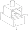
FIG. 1 is a schematic structural diagram of an automatic stamping device for hardware processing;
FIG. 2 is a rear view of an automatic stamping apparatus for hardware processing;
fig. 3 is a schematic diagram of a conveying mechanism and a material taking and placing mechanism in an automatic punching device for hardware processing.
In the figure: 1. a device base; 2. stamping the door frame; 3. a hydraulic lever; 4. punching a block; 5. punching a pressing block downwards; 6. a sliding beam; 7. a slideway; 8. a feeding slide block; 9. a cylinder; 10. a sliding connecting rod; 11. fixing the angle; 12. rotating the connecting rod; 13. a roller; 14. taking and placing the plate; 15. a roller chute; 16. an electromagnet.
Detailed Description
Please refer to fig. 1 ~ 3, in the embodiment of the utility model, an automatic stamping device that hardware processing was used, including device base 1, device base 1's top is located intermediate position department and is fixed with punching press portal 2, punching press portal 2's top is inserted and is established and install hydraulic stem 3, upper punch block 4 is installed to hydraulic stem 3's flexible end, punch block 5 under the top of device base 1 corresponds upper punch block 4's below position department installs, punching press portal 2's inside bilateral symmetry sets up the crossbeam spout that two are parallel to each other, the inboard sliding connection of two crossbeam spouts has conveying mechanism.
In fig. 3: conveying mechanism includes sliding beam 6 of survey in two crossbeam spouts of sliding connection, sliding beam 6's below is located middle section position department and is fixed with slide 7, slide 7's outside sliding connection has pay-off slider 8, pay-off slider 8's bottom symmetry is fixed with two fixed angles 11, and pay-off slider 8's below is provided with gets drop feed mechanism, the cylinder storehouse has been seted up to pay-off slider 8's inside, conveying mechanism can drive the work of getting drop feed mechanism and removing and going on going up unloading, improve device's degree of automation, thereby improve production efficiency.
In fig. 3: the material taking and placing mechanism comprises a cylinder 9 provided with the top end inside a cylinder bin, a sliding connecting rod 10 is fixed at the telescopic end of the cylinder 9, two rotating connecting rods 12 are symmetrically and rotatably connected to the two sides of the tail end of the sliding connecting rod 10, the middle sections of the two rotating connecting rods 12 are rotatably connected with one ends of two fixed angles 11, the tail ends of the two rotating connecting rods 12 are rotatably connected with rollers 13, a taking and placing plate 14 is arranged below the two rotating connecting rods 12, a roller chute 15 is formed in the middle section position of the upper surface of the taking and placing plate 14, the two rollers 13 are slidably connected with the inner side of the roller chute 15, four electromagnets 16 which are arranged in a circumferential mode are arranged at the four corners of the bottom end of the taking and placing plate 14, the telescopic end of the cylinder 9 retracts and pulls the sliding connecting rod 10 to move upwards, the tail end of the sliding connecting rod 10 pulls the two, the two rollers 13 at the ends of the two rotating connecting rods 12 rotate towards the inner side, so that the taking and placing plate 14 is driven to move downwards through sliding between the two rollers and the roller sliding grooves 15, and when the taking and placing plate 14 descends to the upper part of the raw materials, the four electromagnets 16 are electrified to suck the raw materials.
In fig. 2: the finished product standing groove is formed in the position, located at the front end, of the device base 1, the raw material standing groove is formed in the position, located at the rear end, of the upper portion of the device base 1, the product standing groove and the raw material standing groove are convenient to cooperate with a conveying mechanism and take and place the work of the conveying mechanism, and the raw materials are convenient to extract and finished products are convenient to collect by workers.
In fig. 1: two thermovents have been seted up to one side symmetry of lower briquetting 5, and the internally mounted of two thermovents has the fan, and the thermovent gives off for the heat that produces when punching press 5 down, prevents to warp behind the hardware punching press.
In fig. 3: lubricating grease is filled in the roller sliding groove 15, the depth of the roller sliding groove 15 is matched with the outer diameters of the two rollers 13, and the lubricating oil reduces friction force, so that the effect of reducing energy consumption is achieved.
The utility model discloses a theory of operation is: the method comprises the steps of placing raw materials to be punched in a raw material placing groove on one side above a device base 1, starting equipment, driving a taking and placing mechanism below by a feeding slide block 8 to slide to the rear end along the outer side of a slide way 7, simultaneously sliding a sliding beam 6 to the rear end on the inner sides of two beam sliding grooves, stopping when a taking and placing plate 14 reaches the position right above the raw material placing groove, retracting a telescopic end of an air cylinder 9 and pulling a sliding connecting rod 10 to move upwards, pulling two rotating connecting rods 12 to rotate around the joints with two fixed angles 11 by the tail end of the sliding connecting rod 10, rotating two rollers 13 at the tail ends of the two rotating connecting rods 12 downwards close to the inner sides, driving the taking and placing plate 14 to move downwards through sliding between the two roller sliding grooves 15, when the taking and placing plate 14 descends to the position above the raw materials, electrifying four electromagnets 16 to suck the raw materials, then extending the telescopic end, the board 14 will be got to two connecting rods 12 that rotate of rethread and upward pull-up, conveying mechanism drives gets drop feed mechanism and raw materials and moves to the below of stamping block 4, then place the raw materials in the punching press groove of punching press piece 5 down, the flexible end of hydraulic stem 3 stretches out and drives upper stamping block 4 and carry out the punching press to the raw materials, conveying mechanism drives after the punching press is accomplished and gets drop feed mechanism and inhale the finished product, then place the finished product in the inboard of finished product standing groove, can accomplish a punching press work circulation, the device degree of automation is high, and the production efficiency is greatly improved.
The above-mentioned, only be the concrete implementation of the preferred embodiment of the present invention, but the protection scope of the present invention is not limited thereto, and any person skilled in the art is in the technical scope of the present invention, according to the technical solution of the present invention and the utility model, the concept of which is equivalent to replace or change, should be covered within the protection scope of the present invention.
Claims (6)
1. The utility model provides an automatic stamping device that hardware processing was used, includes device base (1), its characterized in that, the top of device base (1) is located intermediate position department and is fixed with punching press portal (2), the top of punching press portal (2) is inserted and is established and install hydraulic stem (3), upper punch block (4) are installed to the flexible end of hydraulic stem (3), the below position department that the top of device base (1) corresponds upper punch block (4) installs lower punch block (5), two parallel crossbeam spouts of each other are seted up to the inside bilateral symmetry of punching press portal (2) the inboard sliding connection of crossbeam spout has conveying mechanism.
2. The automatic stamping device of hardware processing usefulness of claim 1, characterized in that, conveying mechanism includes sliding beam (6) of survey in two crossbeam spouts, the below of sliding beam (6) is located middle section position department and is fixed with slide (7), the outside sliding connection of slide (7) has pay-off slider (8), the bottom symmetry of pay-off slider (8) is fixed with two fixed angles (11), and the below of pay-off slider (8) is provided with gets drop feed mechanism, the cylinder storehouse has been seted up to the inside of pay-off slider (8).
3. The automatic punching device for hardware processing according to claim 2, the material taking and placing mechanism comprises an air cylinder (9) which is provided with the top end inside an air cylinder bin, a sliding connecting rod (10) is fixed at the telescopic end of the air cylinder (9), two rotating connecting rods (12) are symmetrically and rotatably connected to the two sides of the tail end of the sliding connecting rod (10), the middle sections of the two rotating connecting rods (12) are rotatably connected with one ends of two fixed angles (11), the tail ends of the two rotating connecting rods (12) are respectively and rotatably connected with a roller (13), a taking and placing plate (14) is arranged below the two rotating connecting rods (12), the upper surface of the taking and placing plate (14) is provided with a roller sliding chute (15) at the middle section position, two rollers (13) are both connected with the inner side of the roller sliding chute (15) in a sliding way, four electromagnets (16) which are arranged in a circumferential manner are arranged at the positions of four corners of the bottom end of the taking and placing plate (14).
4. The automatic stamping device for hardware processing according to claim 1, characterized in that, the device base (1) is provided with a finished product placing groove at the front position, and a raw material placing groove at the rear position above the device base (1).
5. The automatic stamping device for hardware processing according to claim 1, wherein two heat dissipation ports are symmetrically formed in one side of the lower stamping block (5), and fans are installed inside the two heat dissipation ports.
6. The automatic stamping device for hardware processing according to claim 3, wherein the inside of the roller sliding groove (15) is filled with grease, and the depth of the roller sliding groove (15) is matched with the outer diameter of the two rollers (13).
Priority Applications (1)
| Application Number | Priority Date | Filing Date | Title |
|---|---|---|---|
| CN202021423530.4U CN212944857U (en) | 2020-07-20 | 2020-07-20 | Automatic stamping device that hardware processing was used |
Applications Claiming Priority (1)
| Application Number | Priority Date | Filing Date | Title |
|---|---|---|---|
| CN202021423530.4U CN212944857U (en) | 2020-07-20 | 2020-07-20 | Automatic stamping device that hardware processing was used |
Publications (1)
| Publication Number | Publication Date |
|---|---|
| CN212944857U true CN212944857U (en) | 2021-04-13 |
Family
ID=75393742
Family Applications (1)
| Application Number | Title | Priority Date | Filing Date |
|---|---|---|---|
| CN202021423530.4U Expired - Fee Related CN212944857U (en) | 2020-07-20 | 2020-07-20 | Automatic stamping device that hardware processing was used |
Country Status (1)
| Country | Link |
|---|---|
| CN (1) | CN212944857U (en) |
Cited By (1)
| Publication number | Priority date | Publication date | Assignee | Title |
|---|---|---|---|---|
| CN117483582A (en) * | 2023-12-13 | 2024-02-02 | 浙江司贝宁精工科技有限公司 | Feeding and discharging device of intelligent flexible punching machine |
-
2020
- 2020-07-20 CN CN202021423530.4U patent/CN212944857U/en not_active Expired - Fee Related
Cited By (2)
| Publication number | Priority date | Publication date | Assignee | Title |
|---|---|---|---|---|
| CN117483582A (en) * | 2023-12-13 | 2024-02-02 | 浙江司贝宁精工科技有限公司 | Feeding and discharging device of intelligent flexible punching machine |
| CN117483582B (en) * | 2023-12-13 | 2024-05-24 | 浙江司贝宁精工科技有限公司 | Feeding and discharging device of intelligent flexible punching machine |
Similar Documents
| Publication | Publication Date | Title |
|---|---|---|
| CN102861855B (en) | Automatic riveting device | |
| CN205589981U (en) | Unloader in anti falling automation suitable for flexible panel | |
| CN110328272A (en) | A kind of one-shot multimode sheet metal component punch process transfer matic | |
| CN212944857U (en) | Automatic stamping device that hardware processing was used | |
| CN203726244U (en) | Mechanical feeder applied to tapping machine | |
| CN107521788A (en) | A kind of plastic document presss from both sides production line | |
| CN203265457U (en) | Multistation automatic feeding device for forming plate materials | |
| CN209814910U (en) | Stamping workpiece garbage collection transports transfer chain | |
| CN203140557U (en) | Sash material punching production line for aluminum doors and aluminum windows | |
| CN202290988U (en) | Full-automatic baking varnish keel production equipment | |
| CN203973162U (en) | A kind of self-feeding pressing machine | |
| CN214264829U (en) | Automatic material taking mechanism for numerical control machining of parts | |
| CN206782798U (en) | A kind of handle deforms pinch-grip agency | |
| CN203281757U (en) | Automobile press line waste collection system | |
| CN111804789A (en) | Stamping die for automobile part welding | |
| CN217512722U (en) | Automatic multistation punch press equipment of pay-off | |
| CN207450483U (en) | A kind of plastic document presss from both sides production line | |
| CN202845734U (en) | Full-automatic rotor aluminium casting machine | |
| CN206750943U (en) | A kind of blanking mechanism of automatic riveting lid machine | |
| CN209773287U (en) | Automatic servo lifting and feeding device for conveying die | |
| CN113770270A (en) | Step-by-step punching press | |
| CN207521589U (en) | Punching machine blanking sorting equipment and the punching machine with the device | |
| CN206343580U (en) | A kind of automatic swager | |
| CN206199803U (en) | A kind of dedusting mechanism of laminating machine | |
| CN204976939U (en) | Demolding machine |
Legal Events
| Date | Code | Title | Description |
|---|---|---|---|
| GR01 | Patent grant | ||
| GR01 | Patent grant | ||
| CF01 | Termination of patent right due to non-payment of annual fee | ||
| CF01 | Termination of patent right due to non-payment of annual fee |
Granted publication date: 20210413 |