Novel ecological management artificial floating bed structure
Technical Field
The utility model relates to an ecological improvement technical field especially relates to a novel ecological artificial floating bed structure of administering.
Background
The artificial floating bed is also called artificial floating island and ecological floating bed (ecological floating island). The method is characterized in that an efficient artificial ecosystem is established by taking aquatic plants as a main body, applying the technical principle of soilless culture, taking high polymer materials and the like as carriers and matrixes and applying the principle of intergrowth relationship among species and full utilization of a water space ecological niche and a nutrition ecological niche so as to reduce the pollution load in the water body. The method comprises the steps of splicing, combining and building a special light biological carrier into a required area or geometric shape according to different design requirements, putting the special light biological carrier into a damaged water body, planting screened and domesticated aquatic (terrestrial) plants with strong functions of absorbing organic pollutants in water into a prefabricated floating carrier planting tank, enabling the plants to grow in an environment similar to soilless culture, enabling plant root systems to naturally extend and suspend in the water body, adsorbing and absorbing organic pollutants such as ammonia, nitrogen, phosphorus and the like in water, providing survival and attachment conditions for fishes, shrimps, insects and microorganisms in the water body, and releasing compounds for inhibiting algae growth. Under the combined action of plants, animals, insects and microorganisms, the environmental water quality is purified, and the purpose of restoring and rebuilding a water body ecological system is achieved.
Present artifical floating bed structure is more single, often puts into artifical floating island with the plant of cultivating in advance again on, and operation process is more troublesome, and is comparatively hard when transplanting.
SUMMERY OF THE UTILITY MODEL
The utility model aims at solving the defects existing in the prior art and providing a novel ecological management artificial floating bed structure.
In order to achieve the above purpose, the utility model adopts the following technical scheme: including first superficial seat, first superficial seat internal surface fixedly connected with connecting rod, the connecting rod is kept away from the one end fixedly connected with planting seat of first superficial seat, the surface of first superficial seat is provided with the T-slot, the inside sliding connection in T-slot has the T-shaped piece, the one end fixedly connected with second superficial seat of first superficial seat is kept away from to the T-shaped piece, one side fixedly connected with cross inserted block of T-shaped piece is kept away from to the second superficial seat, the second that the second floated the seat is adjacent floats the seat and keeps away from one side fixedly connected with socket of T-shaped piece, be provided with the third superficial seat between two adjacent second superficial seats.
As a further description of the above technical solution:
the first floating seat and the second floating seat are both hexagonal, and the six sides of the first floating seat are connected with the second floating seat in a sliding mode through T-shaped blocks.
As a further description of the above technical solution:
the first floating seat is parallel to the side face of the second floating seat, and a sliding groove is formed in the side face of the second floating seat.
As a further description of the above technical solution:
the left side face of the third floating seat is fixedly connected with a first connecting plate, the right side face of the third floating seat is fixedly connected with a second connecting plate, and the first connecting plate, the second connecting plate and the sliding groove are connected in a sliding mode.
As a further description of the above technical solution:
the lower surface of the second floating seat is provided with a foam sheet, and the foam sheet is located on the upper portion of the sliding groove.
As a further description of the above technical solution:
the inner surface of the socket is provided with a cross slot, and the size of the cross slot is consistent with that of the cross insertion block.
The utility model discloses following beneficial effect has:
compared with the prior art, this neotype ecological artificial floating bed structure of administering can directly cultivate the plant of different grade type in the floating seat of difference, splicing the use through the connection structure between the floating seat, consequently can select the collocation of plant, convenient make full use of to the floating island structure, a plurality of artifical floating bed structures can carry out the floating island that freely the overlap joint constitutes different area sizes, convenient operation has better ventilation condition, be applicable to different illumination, the plant of ventilation condition is placed.
Drawings
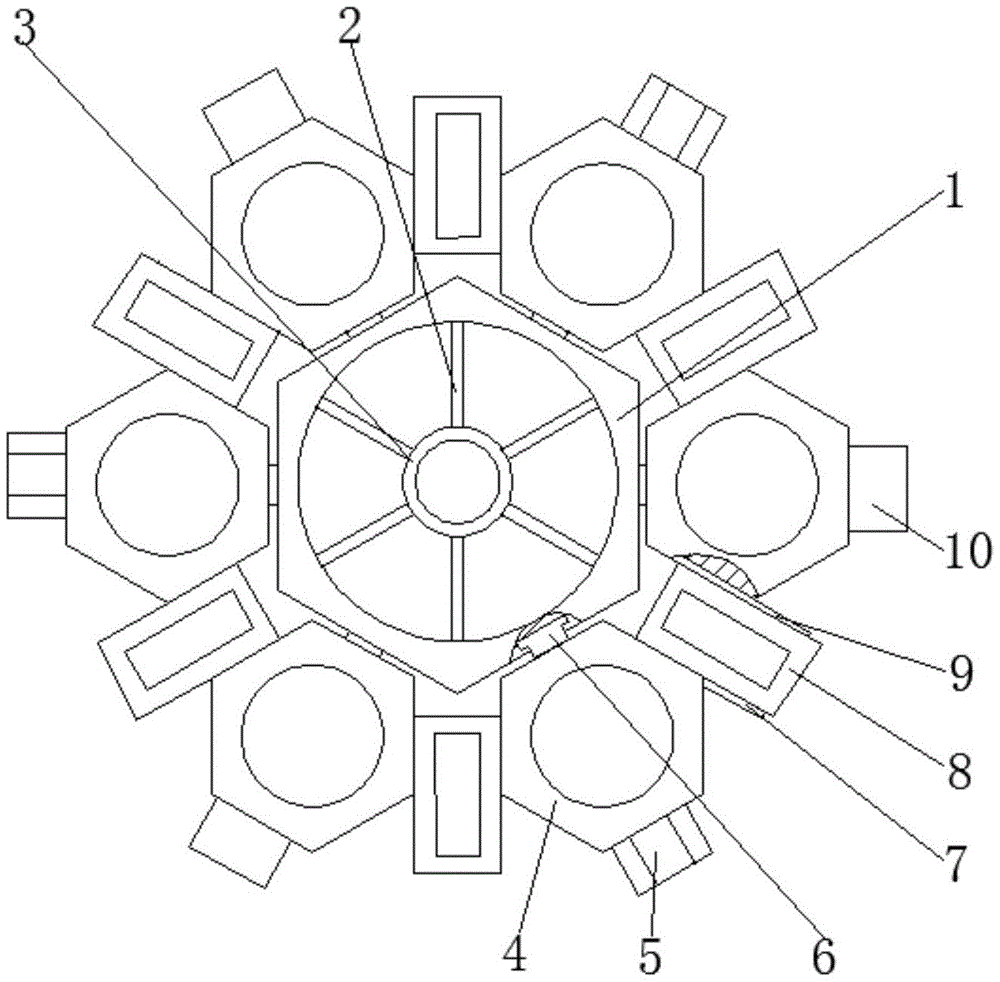
Fig. 1 is a top view of a novel ecological management artificial floating bed structure provided by the utility model;
fig. 2 is a schematic diagram of socket connection of a novel ecological management artificial floating bed structure provided by the utility model;
fig. 3 is the cross-shaped insert block connection schematic diagram of the novel ecological management artificial floating bed structure provided by the utility model.
Illustration of the drawings:
1. a first floating seat; 2. a connecting rod; 3. planting seats; 4. a second floating seat; 5. a cross insert block; 6. a T-shaped block; 7. a first connecting plate; 8. a third floating seat; 9. a second connecting plate; 10. a socket; 11. a foam sheet; 12. a cross slot.
Detailed Description
The technical solutions in the embodiments of the present invention will be described clearly and completely with reference to the accompanying drawings in the embodiments of the present invention, and it is obvious that the described embodiments are only some embodiments of the present invention, not all embodiments. Based on the embodiments in the present invention, all other embodiments obtained by a person skilled in the art without creative work belong to the protection scope of the present invention.
In the description of the present invention, it should be noted that the terms "center", "upper", "lower", "left", "right", "vertical", "horizontal", "inner", "outer", and the like indicate orientations or positional relationships based on the orientations or positional relationships shown in the drawings, and are only for convenience of description and simplification of description, but do not indicate or imply that the device or element referred to must have a specific orientation, be constructed and operated in a specific orientation, and thus, should not be construed as limiting the present invention; the terms "first," "second," and "third" are used for descriptive purposes only and are not to be construed as indicating or implying relative importance, and furthermore, unless otherwise explicitly stated or limited, the terms "mounted," "connected," and "connected" are to be construed broadly and may be, for example, fixedly connected, detachably connected, or integrally connected; can be mechanically or electrically connected; they may be connected directly or indirectly through intervening media, or they may be interconnected between two elements. The specific meaning of the above terms in the present invention can be understood in specific cases to those skilled in the art.
Referring to fig. 1-3, the utility model provides a pair of novel ecological artificial floating bed structure of administering: including first superficial seat 1, first superficial 1 internal surface fixedly connected with connecting rod 2, connecting rod 2 keeps away from first one end fixedly connected with planting seat 3 that floats seat 1, be used for placing the plant that has the water purification function, first superficial 1 surface is provided with the T-slot, the inside sliding connection in T-slot has T-shaped piece 6, first one end fixedly connected with second that floats seat 1 is kept away from to T-shaped piece 6 floats seat 4, be used for placing the plant that has the water purification function, one side fixedly connected with cross inserted block 5 that T-shaped piece 6 was kept away from to second that floats seat 4, one side fixedly connected with socket 10 that T-shaped piece 6 was kept away from to second that second floated seat 4 is adjacent, it floats seat 8 to be provided with the third between seat 4 to adjacent two second, be used for placing the plant that has the water purification function.
First seat 1 that floats, second float seat 4 and all be the hexagon, the hexagonal of first seat 1 that floats all floats seat 4 sliding connection through T-shaped piece 6 and second, first seat 1 that floats parallels with the side of second seat 4 that floats, the side that the second floats seat 4 is provided with the spout, the first connecting plate 7 of left surface fixedly connected with of third float seat 8, the right flank fixedly connected with second connecting plate 9 of third float seat 8, first connecting plate 7, second connecting plate 9 and spout sliding connection, the lower surface that the second floated seat 4 is provided with foam piece 11, a buoyancy for increasing artifical chinampa, foam piece 11 is located the upper portion of spout, the internal surface of socket 10 is provided with cross slot 12, the size that cross slot 12 arrived is unanimous with the size of cross inserted block 5, make things convenient for splice between the chinampa structure.
The working principle is as follows: different illumination in advance, the height of growing, the plant that has the water purification function is cultivated in the floating seat of difference, carry out the overlap joint after the plant grows to reach the uniform size, connect rather than fixed second floating seat 4 through T-shaped piece 6 in the T-shaped inslot of the hexagonal of a first floating seat 1, connect third floating seat 8 in the spout of second floating seat 4 both sides, third floating seat 8 and first floating seat 1, it is used for ventilation to have certain clearance between the second floating seat 4, cross inserted block 5 that connects a plurality of artificial floating island structures through second floating seat 4 side is pegged graft with the cross slot 12 of socket 10, and then splice into the floating island of different area connections, increase the buoyancy of artificial floating island through foam piece 11, make the floating island have certain bearing capacity.
Finally, it should be noted that: although the present invention has been described in detail with reference to the foregoing embodiments, it will be apparent to those skilled in the art that modifications and variations can be made in the embodiments or in part of the technical features of the embodiments without departing from the spirit and the scope of the invention.