CN212351336U - Crown block type three-axis gantry machining center machine - Google Patents
Crown block type three-axis gantry machining center machine Download PDFInfo
- Publication number
- CN212351336U CN212351336U CN202020961942.7U CN202020961942U CN212351336U CN 212351336 U CN212351336 U CN 212351336U CN 202020961942 U CN202020961942 U CN 202020961942U CN 212351336 U CN212351336 U CN 212351336U
- Authority
- CN
- China
- Prior art keywords
- sliding
- machining center
- slide
- crown block
- center machine
- Prior art date
- Legal status (The legal status is an assumption and is not a legal conclusion. Google has not performed a legal analysis and makes no representation as to the accuracy of the status listed.)
- Expired - Fee Related
Links
Images

Abstract
The utility model discloses a crown block formula triaxial longmen machining center machine, including X axle mobile device, Y axle mobile device, Z axle mobile device, processingequipment, be provided with on the first spout with second slide complex second slide rail, Z axle mobile device includes the ram, the second spout has been seted up to the second slide, be provided with on the second spout with ram complex third slide rail, processingequipment installs on the ram, crossbeam, second slide and ram are case font layout structure back in the case. The utility model discloses a crane formula triaxial longmen machining center machine includes X axle mobile device, Y axle mobile device, Z axle mobile device, processingequipment, the utility model discloses a crossbeam, second slide and ram are case font layout structure back in the case for Y axle mobile device and Z axle mobile device's support is symmetry respectively, and the upset of having avoided conventional longmen machining center moving part eccentric to bring is out of shape, in order to obtain higher linear motion precision.
Description
Technical Field
The utility model relates to a technique longmen machining center field, concretely relates to overhead traveling crane formula triaxial longmen machining center machine.
Background
The gantry machining center is a machining center with a main shaft axis perpendicular to the workbench, and the whole structure is in a gantry frame type layout. The concrete structure can be subdivided into a beam fixed type, a beam up-down moving type, a portal frame moving type, a crown block type and other composite forms, and is mainly suitable for processing large parts.
The patent with the application number of CN201710050782.3 discloses a five-axis machining center for restraining a thermal deformation middle-hanging type high-speed crown block, a workbench is directly cast on a base, a left bridge and a right bridge are installed on two sides of the base, linear guide rails are respectively installed on the left bridge and the right bridge, and a cross beam is installed on the left bridge and the right bridge through X-axis sliding blocks on two sides. The middle of the cross beam is hollowed, four guide rails are arranged up and down, and the left sliding seat and the right sliding seat are arranged in the middle of the cross beam through sliding blocks. The left ram and the right ram are connected into a whole through a Y-axis sliding block and a connecting plate, the four linear guide rails are installed on the rams, and the rams are installed between the left sliding seat and the right sliding seat through Z-axis sliding blocks. The utility model provides a hanging design in the moving part, the temperature rise of effective conduction motion production makes the structural deformation homogenization, reduces the influence of thermal deformation to product precision finishing. The utility model discloses a operate steadily, the stable performance is applicable to the precision finishing in vapour turning mold utensil field.
Disclose a longmen machining center that multiaxis was used as in patent application No. CN201710574046.8, including longmen machining center body, the bottom of longmen machining center body is provided with damping washer, damping washer's top is provided with the Z axle, one side of Z axle is provided with the workstation, one side of workstation is provided with the shock attenuation cushion, the top of shock attenuation cushion is provided with the B axle, the top of workstation is provided with the slope axle, the top of slope axle is provided with the X axle, one side of X axle is provided with the Y axle, one side of Y axle is provided with the headstock, the top of headstock is provided with the clamp plate, the top of clamp plate is provided with the ram. The utility model relates to a longmen machining center that multiaxis used can effectual improvement longmen machining center's functionality, has higher stability, can let the accuracy of processing product promote convenience and work efficiency at more stable within range.
The gantry machining center disclosed by the patent can be used in a multi-axis mode, and the functionality of the gantry machining center is effectively improved. However, the gantry machining center has a large vibration sense when machining an object, and the conventional gantry machining center is easy to turn over and deform due to eccentricity when moving a part, so that the accuracy of a machined product is reduced, and the working efficiency is reduced.
SUMMERY OF THE UTILITY MODEL
An object of the utility model is to solve one of the technical problem that exists among the prior art at least, provide a crown block formula triaxial longmen machining center machine.
In order to achieve the above object, the utility model adopts the following technical scheme: the utility model provides a crown block formula triaxial longmen machining center machine, includes X axle mobile device, Y axle mobile device, Z axle mobile device, processingequipment, X axle mobile device includes two sets of matched with first slide rail and first slide, Y axle mobile device includes crossbeam and second slide, both ends are fixed respectively symmetrically on two first slides about the crossbeam, first spout has been seted up on the crossbeam, be provided with on the first spout with second slide complex second slide rail, Z axle mobile device includes the ram, the second spout has been seted up to the second slide, be provided with on the second spout with ram complex third slide rail, processingequipment installs on the ram, crossbeam, second slide and ram are case font layout structure back in the case.
Further, still include the supporting seat, first slide rail is installed on the supporting seat.
Furthermore, the supporting seat is bilateral symmetry 2, and the centre has the workstation, and the supporting seat is fixed on the ground with the workstation, the workstation is located processingequipment under.
Furthermore, the first sliding groove penetrates through the cross beam up and down.
Furthermore, the second slide rail is provided with 4 and 4 second slide rails and sets up on first spout symmetrically from beginning to end, and wherein 2 second slide rails are located first spout upper end, and 2 second slide rails are located the inboard lower extreme of first spout in addition, the second slide is installed on 4 second slide rails symmetrically from beginning to end.
Furthermore, the second sliding chute penetrates the second sliding seat up and down.
Furthermore, the third slide rail is provided with 4 and 4 third slide rails and sets up on the second spout bilateral symmetry, the ram bilateral symmetry is installed on 4 third slide rails.
Furthermore, the X-axis moving device further comprises a driving device, and the driving device is connected with the first sliding seat to drive the first sliding seat to slide along the first sliding rail.
Furthermore, the driving device comprises a driving motor, a screw rod and a screw nut, wherein the screw rod and the screw nut are matched with each other, the driving motor is connected with the screw rod, and the screw nut is connected with the first sliding seat.
Furthermore, the screw rod nut is of an inner cooling structure.
The utility model has the advantages that: as can be seen from the above description of the present invention, compared with the prior art, the crown block type three-axis gantry machining center of the present invention comprises an X-axis moving device, a Y-axis moving device, a Z-axis moving device, and a machining device, wherein the machining device is driven by the X-axis moving device to move along the X-axis, the machining device is driven by the Y-axis moving device to move along the Y-axis, and the machining device is driven by the Z-axis moving device to move along the Z-axis, so as to realize the three-axis movement of the machining device, the left and right ends of the cross beam of the present invention are symmetrically fixed on the two first slides respectively, so as to ensure the left and right symmetry of the cross beam during the movement, and avoid the object from being turned and deformed due to the eccentricity of the X-axis movement, and the cross beam, the second slide and the ram of the present invention are in the box-square layout structure, so that the supports of the Y-axis moving device and the, so as to obtain higher linear motion precision and improve the processing quality of the object.
Drawings
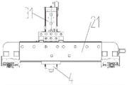
Fig. 1 is a schematic structural view of a crown block type three-axis gantry machining center in a preferred embodiment of the present invention;
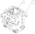
fig. 2 is a schematic front view of a Y-axis moving device, a Z-axis moving device and a processing device according to a preferred embodiment of the present invention;
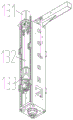
fig. 3 is a schematic structural view of a second slide carriage according to a preferred embodiment of the present invention;
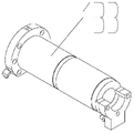
fig. 4 is a schematic structural diagram of a driving device in a preferred embodiment of the present invention;
fig. 5 is a schematic structural diagram of a feed screw nut according to a preferred embodiment of the present invention.
Reference numerals: 1. an X-axis moving device; 11. a first slide rail; 12. a first slider; 13. a drive device; 131. a drive motor; 132. a screw rod; 133. a feed screw nut; 2. a Y-axis moving device; 21. a cross beam; 22. a second slide carriage; 23. a second slide rail; 24. a first chute; 3. a Z-axis moving device; 31. a ram; 32. a third slide rail; 33. a second chute; 4. a processing device; 5. a supporting seat; 6. a work bench.
Detailed Description
The technical solution of the present invention will be described clearly and completely with reference to the accompanying drawings in the embodiments of the present invention, and it is obvious that the described embodiments are only some embodiments of the present invention, not all embodiments.
In the description of the present invention, it is to be noted that, unless otherwise explicitly specified or limited, the terms "connected" and "connected" are to be interpreted broadly, and may be, for example, fixedly connected, detachably connected, or integrally connected; can be mechanically or electrically connected; may be directly connected or indirectly connected through an intermediate. The specific meaning of the above terms in the present invention can be understood in specific cases to those skilled in the art.
Referring to fig. 1-5, a preferred embodiment of the present invention is a crown block type three-axis gantry machining center, including an X-axis moving device 1, a Y-axis moving device 2, a Z-axis moving device 3, and a machining device 4, where the X-axis moving device 1 includes two sets of first slide rails 11 and first slide seats 12, the Y-axis moving device 2 includes a cross beam 21 and second slide seats 22, the left and right ends of the cross beam 21 are symmetrically fixed on the two first slide seats 12, the cross beam 21 is provided with a first slide groove 24, the first slide groove 24 is provided with a second slide rail 23 matched with the second slide seats 22, the Z-axis moving device 3 includes a ram 31, the second slide seat 22 is provided with a second slide groove 33, the second slide groove 33 is provided with a third slide rail 32 matched with the ram 31, the machining device 4 is installed on the ram 31, the cross beam 21, the second slide carriage 22 and the ram 31 are in a box-in-box-shaped layout structure.
The crown block type three-axis gantry machining center machine of the utility model comprises an X-axis moving device 1, a Y-axis moving device 2, a Z-axis moving device 3 and a machining device 4, wherein the machining device 4 is driven to move along the X axis by the X-axis moving device 1, the machining device 4 is driven to move along the Y axis by the Y-axis moving device 2, and the machining device 4 is driven to move along the Z axis by the Z-axis moving device 3 so as to realize the three-axis movement of the machining device 4, the left end and the right end of a beam 21 of the utility model are respectively and symmetrically fixed on two first sliding seats 12, so that the beam 21 is ensured to be symmetrical when moving, the overturn deformation caused by the eccentricity of the X axis movement is avoided, and the beam 21, the second sliding seat 22 and a ram 31 of the utility model are in a box-square-shaped layout structure, so that the supports of the Y-axis moving device 2 and the Z-axis moving device 3 are respectively symmetrical, the overturn, so as to obtain higher linear motion precision and improve the processing quality of the object.
As a preferred embodiment of the present invention, it may also have the following additional technical features:
in this embodiment, still include supporting seat 5, first slide rail 11 is installed on supporting seat 5, supports two first slide rails 11 through supporting seat 5, and wherein, supporting seat 5 detachable sets up to support two first slide rails 11 respectively, but material saving.
In this embodiment, the supporting seat 5 is bilateral symmetry 2, has workstation 6 in the middle, and supporting seat 5 and workstation 6 are fixed on the ground, workstation 6 is located processingequipment 4 under. The object to be processed is placed by the working table 6, the working table 6 is located right below the processing device 4 so that the processing device 4 processes the object, and the fixed working table 6 can bear heavy load without affecting the operation of the processing device 4.
In this embodiment, the first sliding groove 24 penetrates the cross beam 21 up and down, and the second sliding seat 22 can be located inside the cross beam 21 by arranging the first sliding groove 24 penetrating the cross beam 21 up and down to form a box structure with the cross beam 21, so that the stability of the whole machining center machine is improved, and the machining efficiency and the quality are improved.
In this embodiment, the second slide rail 23 is provided with 4 and 4 second slide rails 23 symmetrically arranged on the first slide groove 24 front and back, wherein 2 second slide rails 23 are located at the upper end of the first slide groove 24, the other 2 second slide rails 23 are located at the lower end of the inner side of the first slide groove 24, and the second slide 22 is symmetrically arranged on the 4 second slide rails 23 front and back. The second slide 22 is symmetrically arranged on the 4 second slide rails 23 in a front-back manner, so that the whole Y-axis moving device 2 is symmetrically distributed, the phenomenon that the object is turned and deformed due to the fact that the object moves eccentrically on the Y axis is avoided, and the processing efficiency is improved.
In this embodiment, the second sliding groove 33 penetrates the second sliding seat 22 up and down, and the ram 31 can penetrate the second sliding seat 22 up and down by arranging the second sliding groove 33 penetrating the cross beam 21 up and down, so as to form a box-in-box structure with the second sliding seat 22, thereby improving the stability of the whole machining center and improving the machining efficiency and quality.
In the present embodiment, the third slide rail 32 is provided with 4, and 4 third slide rails 32 are symmetrically arranged on the second sliding chute 33, and the ram 31 is symmetrically arranged on the 4 third slide rails 32. Install 4 third slide rails 32 through with ram 31 bilateral symmetry, make whole Z axle mobile device 3 be the symmetric distribution, avoid the article to remove off-centre at the Z axle and lead to the upset to warp, improve machining efficiency to ram 31 also is the symmetric distribution, makes ram 31 atress more even when the article adds man-hour, promotes the stability of whole machining center machine, improves machining efficiency and quality.
In this embodiment, the X-axis moving device 1 further includes a driving device 13, the driving device 13 is connected to the first sliding base 12 to drive the first sliding base 12 to slide along the first sliding rail 11, and the X-axis moving device 1 is driven by the driving device 13 to move the first sliding base 12 and further move the beam 21; specifically, the Y-axis moving device 2 and the Z-axis moving device 3 of the present invention have the same driving structure, and can be driven by the same driving mechanism, which is not described in detail herein.
In the present embodiment, the driving device 13 includes a driving motor 131 and a screw 132 and a screw nut 133 which are matched, the driving motor 131 is connected with the screw 132, and the screw nut 133 is connected with the first carriage 12. The driving device 13 adopts the driving motor 131 and the screw rod 132 and the screw nut 133 which are matched with each other, so as to conveniently control the movement of the first sliding seat 12, and make the movement of the first sliding seat 12 more stable.
In this embodiment, the feed screw nut 133 has an inner cooling structure, and the feed screw nut 133 has an inner cooling structure, so that the temperature rise of the feed screw nut 133 due to heat generation can be reduced.
The above additional technical features can be freely combined and used in superposition by those skilled in the art without conflict.
It is to be understood that the present invention has been described with reference to certain embodiments, and that various changes or equivalents may be substituted for elements thereof by those skilled in the art without departing from the spirit and scope of the invention. In addition, many modifications may be made to adapt a particular situation or material to the teachings of the invention without departing from the essential scope thereof. Therefore, the present invention is not limited to the specific embodiments disclosed herein, and all embodiments falling within the scope of the claims of the present application are intended to be covered by the present invention.
Claims (10)
1. The utility model provides a crown block formula triaxial longmen machining center machine which characterized in that: the X-axis moving device (1), the Y-axis moving device (2), the Z-axis moving device (3) and the machining device (4) are included, the X-axis moving device (1) comprises two sets of matched first sliding rails (11) and first sliding seats (12), the Y-axis moving device (2) comprises a cross beam (21) and second sliding seats (22), the left end and the right end of the cross beam (21) are symmetrically fixed on the two first sliding seats (12) respectively, a first sliding chute (24) is formed in the cross beam (21), a second sliding rail (23) matched with the second sliding seat (22) is arranged on the first sliding chute (24), the Z-axis moving device (3) comprises a ram (31), a second sliding chute (33) is formed in the second sliding chute (33), a third sliding rail (32) matched with the ram (31) is arranged on the second sliding chute (33), and the machining device (4) is installed on the ram (31), the cross beam (21), the second sliding seat (22) and the ram (31) are of a box-in-box square-shaped layout structure.
2. The crown block type three-axis gantry machining center machine according to claim 1, characterized in that: still include supporting seat (5), first slide rail (11) are installed on supporting seat (5).
3. The crown block type three-axis gantry machining center machine according to claim 2, characterized in that: the supporting seat (5) is bilateral symmetry 2, has workstation (6) in the middle of, and supporting seat (5) and workstation (6) are fixed on the ground, workstation (6) are located processingequipment (4) under.
4. The crown block type three-axis gantry machining center machine according to claim 1, characterized in that: the first sliding groove (24) penetrates through the cross beam (21) vertically.
5. The crown block type three-axis gantry machining center machine according to claim 1, characterized in that: the second slide rail (23) is provided with 4 and 4 second slide rails (23) and symmetrically arranged on the first sliding groove (24) front and back, wherein 2 second slide rails (23) are positioned at the upper end of the first sliding groove (24), the other 2 second slide rails (23) are positioned at the lower end of the inner side of the first sliding groove (24), and the second slide base (22) is symmetrically arranged on the 4 second slide rails (23) front and back.
6. The crown block type three-axis gantry machining center machine according to claim 1, characterized in that: the second sliding chute (33) penetrates the second sliding seat (22) vertically.
7. The crown block type three-axis gantry machining center machine according to claim 1, characterized in that: the third slide rail (32) is provided with 4 and 4 third slide rails (32) which are arranged on the second sliding groove (33) in a bilateral symmetry mode, and the ram (31) is arranged on the 4 third slide rails (32) in a bilateral symmetry mode.
8. The crown block type three-axis gantry machining center machine according to claim 1, characterized in that: the X-axis moving device (1) further comprises a driving device (13), wherein the driving device (13) is connected with the first sliding seat (12) to drive the first sliding seat (12) to slide along the first sliding rail (11).
9. The crown block type three-axis gantry machining center machine according to claim 8, characterized in that: the driving device (13) comprises a driving motor (131), a screw rod (132) and a screw nut (133) which are matched with each other, the driving motor (131) is connected with the screw rod (132), and the screw nut (133) is connected with the first sliding seat (12).
10. The crown block type three-axis gantry machining center machine according to claim 9, characterized in that: the feed screw nut (133) is of an inner cooling structure.
Priority Applications (1)
| Application Number | Priority Date | Filing Date | Title |
|---|---|---|---|
| CN202020961942.7U CN212351336U (en) | 2020-05-29 | 2020-05-29 | Crown block type three-axis gantry machining center machine |
Applications Claiming Priority (1)
| Application Number | Priority Date | Filing Date | Title |
|---|---|---|---|
| CN202020961942.7U CN212351336U (en) | 2020-05-29 | 2020-05-29 | Crown block type three-axis gantry machining center machine |
Publications (1)
| Publication Number | Publication Date |
|---|---|
| CN212351336U true CN212351336U (en) | 2021-01-15 |
Family
ID=74156178
Family Applications (1)
| Application Number | Title | Priority Date | Filing Date |
|---|---|---|---|
| CN202020961942.7U Expired - Fee Related CN212351336U (en) | 2020-05-29 | 2020-05-29 | Crown block type three-axis gantry machining center machine |
Country Status (1)
| Country | Link |
|---|---|
| CN (1) | CN212351336U (en) |
-
2020
- 2020-05-29 CN CN202020961942.7U patent/CN212351336U/en not_active Expired - Fee Related
Similar Documents
| Publication | Publication Date | Title |
|---|---|---|
| CN111515759A (en) | Crown block type three-axis gantry machining center machine | |
| CN201470957U (en) | Planer vertical high-speed numerical control milling machine | |
| KR20120084909A (en) | A high-rigidity multipurpose manufacturing device | |
| CN104607702A (en) | Vertical finish-milling machine | |
| EP3045263B1 (en) | Machine tool | |
| CN205129392U (en) | Large -scale overhead bridge type longmen pentahedron machining center | |
| CN206047625U (en) | A kind of gantry machining center | |
| CN217194077U (en) | Hoisting type drilling and milling device for processing door and window profiles | |
| CN204504315U (en) | A kind of vertical Finish Milling Machine | |
| CN109482944A (en) | Gantry mechanism precision machine tool | |
| CN202607230U (en) | Large-scale double-column-type boring-milling machining center | |
| CN114406370A (en) | Movable beam type gantry structure of numerical control electric spark forming machine tool | |
| CN207615668U (en) | A kind of numerical control movable post vertical lathe | |
| CN202029007U (en) | Bridge-type numerical control planogrinder structure | |
| CN212351336U (en) | Crown block type three-axis gantry machining center machine | |
| CN218612804U (en) | Double-gantry double-station driving structure | |
| CN111975135A (en) | Numerical control gear machining machine tool | |
| CN115770915A (en) | Gantry machining unit of electric discharge machine tool | |
| CN111136476A (en) | Ram type double-exchange workbench machine tool | |
| CN212634960U (en) | Drilling and tapping center with movable spindle box | |
| CN213135184U (en) | Full-automatic two-sided milling deburring device for battery tray | |
| CN201702508U (en) | Flight light path laser processing machine tool | |
| CN204657962U (en) | A kind of gantry frame | |
| CN204075998U (en) | A kind of column for grinding machine | |
| CN208006563U (en) | The sleeping cold carving machine of mill of numerical control |
Legal Events
| Date | Code | Title | Description |
|---|---|---|---|
| GR01 | Patent grant | ||
| GR01 | Patent grant | ||
| CF01 | Termination of patent right due to non-payment of annual fee | ||
| CF01 | Termination of patent right due to non-payment of annual fee |
Granted publication date: 20210115 Termination date: 20210529 |