CN212255619U - Multichannel hinders poor balanced and gathers and solidify all-in-one soon - Google Patents
Multichannel hinders poor balanced and gathers and solidify all-in-one soon Download PDFInfo
- Publication number
- CN212255619U CN212255619U CN202020697134.4U CN202020697134U CN212255619U CN 212255619 U CN212255619 U CN 212255619U CN 202020697134 U CN202020697134 U CN 202020697134U CN 212255619 U CN212255619 U CN 212255619U
- Authority
- CN
- China
- Prior art keywords
- driving device
- fixing
- battery module
- plate
- seat
- Prior art date
- Legal status (The legal status is an assumption and is not a legal conclusion. Google has not performed a legal analysis and makes no representation as to the accuracy of the status listed.)
- Active
Links
Images


Classifications
-
- Y—GENERAL TAGGING OF NEW TECHNOLOGICAL DEVELOPMENTS; GENERAL TAGGING OF CROSS-SECTIONAL TECHNOLOGIES SPANNING OVER SEVERAL SECTIONS OF THE IPC; TECHNICAL SUBJECTS COVERED BY FORMER USPC CROSS-REFERENCE ART COLLECTIONS [XRACs] AND DIGESTS
- Y02—TECHNOLOGIES OR APPLICATIONS FOR MITIGATION OR ADAPTATION AGAINST CLIMATE CHANGE
- Y02E—REDUCTION OF GREENHOUSE GAS [GHG] EMISSIONS, RELATED TO ENERGY GENERATION, TRANSMISSION OR DISTRIBUTION
- Y02E60/00—Enabling technologies; Technologies with a potential or indirect contribution to GHG emissions mitigation
- Y02E60/10—Energy storage using batteries
-
- Y—GENERAL TAGGING OF NEW TECHNOLOGICAL DEVELOPMENTS; GENERAL TAGGING OF CROSS-SECTIONAL TECHNOLOGIES SPANNING OVER SEVERAL SECTIONS OF THE IPC; TECHNICAL SUBJECTS COVERED BY FORMER USPC CROSS-REFERENCE ART COLLECTIONS [XRACs] AND DIGESTS
- Y02—TECHNOLOGIES OR APPLICATIONS FOR MITIGATION OR ADAPTATION AGAINST CLIMATE CHANGE
- Y02P—CLIMATE CHANGE MITIGATION TECHNOLOGIES IN THE PRODUCTION OR PROCESSING OF GOODS
- Y02P70/00—Climate change mitigation technologies in the production process for final industrial or consumer products
- Y02P70/50—Manufacturing or production processes characterised by the final manufactured product
Landscapes
- Secondary Cells (AREA)
Abstract
The utility model discloses a multichannel hinders poor equilibrium and gathers can all-in-one fast admittedly, include: workstation, anodal probe locating plate, the poor detection mechanism of top solid screw fixation board, spacing clamp plate, multichannel hinder poor detection mechanism, resistance adjustment mechanism and gather and to construct admittedly soon, anodal probe locating plate setting is located between two carrier carriages on the workstation, and the solid screw fixation board setting in top is located anodal probe locating plate below on the workstation, spacing clamp plate setting is located anodal probe locating plate top on the workstation, and the multichannel hinders poor detection mechanism and carries out the contact resistance detection of battery in the battery module, and resistance adjustment mechanism sets up in the workstation below, realizes contact resistance's regulation, and it is solid that the mechanism carries out the light of battery module admittedly soon to gather. In this way, multichannel hinder poor equilibrium and gather and to solidify all-in-one soon, realized the resistance detection of battery module, hinder poor equilibrium and the solid automated production of light, efficient has promoted the security of production.
Description
Technical Field
The utility model relates to a battery module cold welding technical field especially relates to a multichannel hinders poor equilibrium and gathers can solid all-in-one soon.
Background
With the development of new energy vehicles, the use of battery modules is more and more extensive. In order to increase the storage capacity of the battery module, hundreds of batteries need to be installed in the battery module to work together. Because the battery quantity in the battery module is more, can consider to utilize the mode of glue cold welding to promote stability, for example utilize conducting resin to carry out being connected of battery negative pole and female arranging or being connected of battery side and outer frame, then shine the solidification with the ultraviolet ray, production efficiency is higher.
In the actual production process, because cold solder joint is more, the point that needs processing on battery module hole quantity is more, has brought the difficulty for the ultraviolet irradiation solidification, and work efficiency is low, still leads to ultraviolet leakage problem easily, influences the security of production.
In addition, the direct ultraviolet irradiation curing after the battery module dispensing often has quality defects, because the contact pressure of partial battery cathodes and the busbar is different, the contact resistance difference between the battery and the busbar is larger, and the conductive adhesive is difficult to adjust after curing, so that potential safety hazards exist in products. Therefore, the battery module is required to be subjected to resistance difference detection and adjustment before photocuring, and in the prior art, equipment capable of adjusting the contact pressure between the negative electrode of the battery and the busbar in the battery module is not provided, and only the resistance detection, adjustment and photocuring can be carried out independently, so that the working efficiency is low, and the process connectivity is poor.
SUMMERY OF THE UTILITY MODEL
The utility model discloses the main technical problem who solves provides a multichannel hinders poor equilibrium and gathers can solid all-in-one soon, and the automatic contact resistance who carries out the battery module detects, hinders poor equilibrium regulation and light admittedly, promotes production efficiency.
In order to solve the technical problem, the utility model discloses a technical scheme be: the utility model provides a balanced and gather fast solid all-in-one of multichannel resistance difference, includes:
the device comprises a workbench, wherein two carrier conveying frames are arranged on the workbench in parallel, a battery module carrier is arranged on each carrier conveying frame, a battery module is arranged in each battery module carrier, and a dispensing hole is formed in each battery module;
the positive probe positioning plate is arranged on the workbench and positioned between the two carrier conveying frames, a first telescopic driving device for supporting the positive probe positioning plate to lift is arranged on the workbench, positive probe positioning holes corresponding to the anodes at the bottom of the batteries in the battery module in a one-to-one mode are formed in the positive probe positioning plate, and positive probes are arranged on the positive probe positioning holes;
the jacking screw fixing plate is arranged on the workbench and positioned below the positive probe positioning plate, and jacking screws which correspond to the positive probes one by one are arranged on the jacking screw fixing plate;
the limiting pressing plate is arranged on the workbench and positioned above the positive probe positioning plate, and first light guide holes which correspond to the dispensing holes one to one are formed in the limiting pressing plate;
the multi-channel resistance difference detection mechanism is arranged on the workbench to detect the contact resistance of the battery in the battery module and find out the battery with abnormal contact resistance;
the resistance adjusting mechanism is arranged below the workbench and used for rotationally driving a jacking screw below the battery with abnormal contact resistance to realize the adjustment of the contact resistance;
the energy-gathering quick-fixing mechanism is arranged on the workbench to perform light fixing of the battery module.
In the utility model discloses a preferred embodiment, multichannel hinders poor detection mechanism and includes resistance detector, support frame, slide, second flexible drive arrangement and negative pole probe locating plate, the support frame sets up respectively on the workstation and lies in the outside of carrier carriage, the slide sets up in the support frame top, the vertical setting of second flexible drive arrangement is on the slide and point downwards, negative pole probe locating plate sets up in the bottom of second flexible drive arrangement, be provided with the negative pole probe with positive pole probe one-to-one on the negative pole probe locating plate, be provided with the hole of dodging with negative pole probe one-to-one on the spacing clamp plate, positive pole probe and negative pole probe are connected with resistance detector linearity respectively.
In a preferred embodiment of the present invention, the supporting frame is provided with a guide rail located at the bottom of the slide seat and a horizontal driving device for driving the slide seat to move along the guide rail.
In a preferred embodiment of the present invention, the horizontal driving device employs an electric screw sliding table, and the first telescopic driving device and the second telescopic driving device employ cylinders, respectively.
In the utility model discloses a preferred embodiment, gather and to solidify mechanism soon and include outer frame, fixed plate, crane, third lift drive, curing lamp and lamp shade, the outer frame sets up on the workstation, the fixed plate sets up on the outer frame and is located the top of spacing clamp plate, third lift drive vertical setting is on the fixed plate and point downwards, the crane sets up in third lift drive bottom, the curing lamp sets up in the crane, the lamp shade sets up in the curing lamp bottom and is located spacing clamp plate directly over.
In a preferred embodiment of the present invention, the third lifting driving device employs an electric cylinder or an air cylinder, the side of the lampshade is provided with an air inlet, and the air inlet is provided with a fan.
In a preferred embodiment of the present invention, a blocking plate is disposed at the bottom of the lamp cover, and a second light guiding hole corresponding to the first light guiding hole is disposed on the blocking plate.
In a preferred embodiment of the present invention, the resistance adjusting mechanism includes a locking servo motor and a motor moving device, the locking servo motor is disposed on the motor moving device, a wrench chuck is disposed on the top of the locking servo motor, and a screw wrench corresponding to the top-fixing screw is disposed on the wrench chuck.
In a preferred embodiment of the present invention, the motor moving device comprises an X-axis slide rail, a Z-axis slide rail, an X-direction servo driving device, a first moving seat, a second moving seat, a third moving seat, a Y-direction servo driving device and a Z-direction driving device, the first moving seat is disposed on the X-axis slide rail and the X-direction servo driving device which are distributed in parallel, the Y-direction servo driving device is disposed on the first moving seat, the second moving seat is disposed on the Y-direction servo driving device, the Z-axis slide rail is vertically disposed on the second moving seat, the third moving seat is disposed on the Z-axis slide rail, the Z-direction driving device is disposed on the second moving seat to drive the third moving seat to move up and down, the locking servo motor is disposed on the third moving seat and is pointed upward to the top fixing screw, a coupling is disposed between the output shaft of the locking servo motor and the wrench chuck, and a bearing seat corresponding to the wrench chuck is arranged on the third movable seat, and an origin sensor corresponding to the wrench chuck is arranged below the bearing seat.
In a preferred embodiment of the present invention, the X-direction servo driving device and the Y-direction servo driving device respectively employ an electric screw sliding table, the Z-direction driving device is a cylinder or an electric cylinder, the third moving seat is provided with a connecting seat on one side, the Z-direction driving device is provided with a push rod inserted into the connecting seat on the top, the push rod is sleeved with a first spring, the top fixing screw is provided with a second spring on the top, the two sides of the top fixing screw fixing plate are provided with a sensor fixing plate, and the sensor fixing plate is provided with a light curtain corresponding to the top fixing screw on the inner side.
The utility model has the advantages that: the utility model provides a multichannel hinders poor balanced and can gather fast solid all-in-one, send the battery module carrier of battery module to the positive pole probe locating plate top through the carrier carriage, jack up the battery module carrier through positive pole probe locating plate, and utilize spacing clamp plate to carry out the top spacing of battery module, at this moment, positive pole probe and the anodal contact of battery bottom in the battery module, the slide moves to spacing clamp plate top, through the decline of negative pole probe locating plate insert the negative pole probe in the battery module and contact with battery top negative pole or female row, carry out the contact resistance multichannel of battery and detect, find out the battery of contact resistance anomaly, carry out the rotation of top solid screw through resistance adjustment mechanism, realize the regulation of contact resistance, realize hindering poor balanced, the slide resets, carry out the light of battery module through gathering fast solid mechanism, automatic production is realized, the production efficiency is high, and the production safety is improved.
Drawings
In order to more clearly illustrate the technical solutions of the embodiments of the present invention, the drawings used in the description of the embodiments are briefly introduced below, and it is obvious that the drawings in the following description are only some embodiments of the present invention, and for those skilled in the art, other drawings can be obtained without inventive work, wherein:
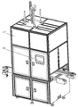
FIG. 1 is a schematic structural view of a preferred embodiment of the multi-channel differential resistance balancing and energy-gathering quick-fixing integrated machine of the present invention;
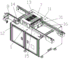
FIG. 2 is a schematic view of the structure of FIG. 1 with portions broken away;
FIG. 3 is a schematic view of the structure of the table of FIG. 2;
FIG. 4 is a schematic view of the multi-channel impedance difference detection mechanism of FIG. 3 with the structure removed;
FIG. 5 is another angular view of FIG. 4;
FIG. 6 is an enlarged view of portion A of FIG. 5;
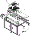
FIG. 7 is an exploded view of FIG. 4;
FIG. 8 is a cross-sectional view of the positive probe positioning plate, the limiting pressure plate and other structures in FIG. 4;
FIG. 9 is a schematic structural view of the energy concentrating quick fastening mechanism of FIG. 2;
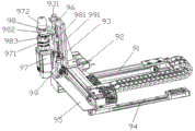
fig. 10 is a schematic structural view of the resistance adjustment mechanism in fig. 2.
Detailed Description
The technical solutions in the embodiments of the present invention will be described clearly and completely below, and it should be apparent that the described embodiments are only some embodiments of the present invention, but not all embodiments. Based on the embodiments in the present invention, all other embodiments obtained by a person skilled in the art without creative efforts belong to the protection scope of the present invention.
Referring to fig. 1 to 10, an embodiment of the present invention includes:
the multi-channel block difference balancing and energy gathering fast-fixing all-in-one machine shown in fig. 1-4 comprises: the automatic production line comprises a workbench 1, an anode probe positioning plate 31, a top fixing screw fixing plate 15, a limiting pressing plate 7, a multi-channel resistance difference detection mechanism, a resistance adjusting mechanism 9 and an energy-gathering quick fixing mechanism, wherein the battery module is conveyed, contact resistance multi-channel detection, resistance difference balance adjustment and light fixation are carried out, and automatic production is realized.
Two carrier conveying frames 8 are arranged on the workbench 1 in parallel, a battery module carrier 11 is arranged on the carrier conveying frame 8, a battery module 18 is arranged in the battery module carrier 11, and a glue dispensing hole is formed in the battery module 18, so that glue dispensing construction is convenient to carry out. The conveying of the battery module 18 after the glue dispensing is carried out through the carrier conveying frame 8, the carrier conveying frame 8 adopts a servo motor to drive a synchronous belt or a chain, and the conveying precision of the battery module carrier 11 and the battery module 18 is ensured.
The positive probe positioning plate 31 is arranged on the workbench 1 and between the two carrier conveying frames 8, so that the carrier conveying frames 8 can convey the battery module 18 to the position above the positive probe positioning plate 31. Carrier carriage 8 outside is provided with blocks cylinder 14, blocks that cylinder 14 output is provided with the stopper that extends to positive pole probe locating plate 31 the place ahead, carries out the accurate spacing of battery module carrier 11. The workbench 1 is provided with a first telescopic driving device 16 for supporting the anode probe positioning plate 31 to ascend and descend, the anode probe positioning plate 31 is provided with an anode probe positioning hole in one-to-one correspondence with the battery bottom anode in the battery module 18, the anode probe positioning hole is provided with an anode probe 19 with a stepped shaft structure, and after the anode probe positioning plate 31 ascends, the anode probe 19 is in one-to-one contact with the battery bottom anode in the battery module 18, so that resistance detection is facilitated.
The jacking screw fixing plate 15 is fixed on the workbench 1 and located below the positive electrode probe positioning plate 31, jacking screws 20 corresponding to the positive electrode probes 19 one to one are arranged on the jacking screw fixing plate 15, threaded holes 30 corresponding to the jacking screws 20 are formed in the jacking screw fixing plate 15, and lifting adjustment is performed through rotation of the jacking screws 20, so that bottom limiting and jacking adjustment of the positive electrode probes 19 are performed. In order to improve the detection precision, the bottom of the positive electrode probe 19 is provided with an insulator 21, as shown in fig. 8, the insulator 21 is insulated and protected when contacting with the top fixing screw 20, so as to ensure the detection accuracy.
The limiting pressing plate 7 is arranged on the workbench 1 and located above the positive electrode probe positioning plate 31, the battery module 18 is limited at the top after rising, and the supporting plates 12 connected with the outer side face of the carrier conveying frame 8 are arranged on two sides of the limiting pressing plate 7, so that the structure is stable. The limiting pressing plate 7 is provided with first light guide holes 13 which correspond to the dispensing holes one to one, and subsequent light fixation is facilitated.
The multi-channel resistance difference detection mechanism is arranged on the workbench 1 to detect the contact resistance of the battery in the battery module 18 and find out the battery with abnormal contact resistance. As shown in fig. 3, the multi-channel resistance difference detection mechanism includes a resistance detector (the resistance detector is linearly connected to or integrated in the controller 38) and a support frame 37, a slide 10, a second telescopic driving device 33 and a negative probe positioning plate 35, the support frame 37 is respectively disposed on the workbench 1 and located outside the carrier transport rack 8, the slide 10 is disposed above the support frame 37, a guide rail 36 located at the bottom of the slide 10 and a horizontal driving device 32 driving the slide to move along the guide rail 36 are disposed on the support frame 37, the horizontal driving device 32 employs an electric screw sliding table, and the controller 38 controls the horizontal driving device 32 to improve the displacement accuracy of the slide 10.
The second telescopic driving device 33 is vertically arranged on the sliding seat 10 and points downwards, the negative probe positioning plate 35 is arranged at the bottom of the second telescopic driving device 33, the first telescopic driving device 16 and the second telescopic driving device 33 respectively adopt cylinders, the control is flexible, and the second telescopic driving device 33 drives the negative probe positioning plate 35 to ascend and descend.
Be provided with the negative probe 34 with positive probe 19 one-to-one on the negative probe locating plate 35, during the poor detection of hindering, slide 10 removes negative probe locating plate 35 to battery module 18 top, through the decline of negative probe locating plate 35 and negative probe 34, be provided with the hole of dodging with negative probe 34 one-to-one on the spacing clamp plate 7, make negative probe 34 pass and dodge the hole and contact with battery module 18's battery top negative pole or female arranging, and simultaneously, positive probe 19 and negative probe 34 are respectively with resistance detector linear connection, carry out resistance detection, find out the battery of resistance difference, carry out subsequent poor balanced regulation of hindering.
The resistance adjusting mechanism is arranged below the workbench 1, and is used for rotationally driving the ejection screw 20 below the battery with abnormal contact resistance, so that the contact pressure between the negative electrode of the battery and the busbar is increased, and the reduction of the contact resistance is realized. As shown in fig. 10, the resistance adjusting mechanism 9 includes a locking servo motor 97 and a motor moving device, the locking servo motor 97 is disposed on the motor moving device, a wrench chuck 972 is disposed on the top of the locking servo motor 97, and a screw wrench, such as a hexagon wrench, corresponding to the jacking screw 20 is disposed on the wrench chuck 972, so as to facilitate the rotation of the jacking screw 20.
In this embodiment, the motor moving device includes an X-axis slide rail 94, a Z-axis slide rail 96, an X-direction servo driving device 91, a first moving base 95, a second moving base 93, a third moving base 98, a Y-direction servo driving device 92, and a Z-direction driving device 99, the first moving base 95 is disposed on the X-axis slide rail 94 and the X-direction servo driving device 91 which are distributed in parallel, and the X-direction displacement driving of the first moving base 95 is performed by the X-direction servo driving device 91.
The Y-direction servo drive device 92 is provided on the first carriage 95, the second carriage 93 is provided on the Y-direction servo drive device 92, and the Y-direction displacement drive of the second carriage 93 is performed by the Y-direction servo drive device 92. The X-direction servo driving device 91 and the Y-direction servo driving device 92 respectively adopt an electric screw rod sliding table, and the displacement precision is high.
The Z-axis slide rail 96 is vertically arranged on the second moving seat 93, the third moving seat 98 is arranged on the Z-axis slide rail 96, the Z-direction driving device 99 is arranged on the second moving seat 93 to drive the third moving seat 98 to ascend and descend, and the Z-direction driving device 99 is an air cylinder or an electric cylinder and acts rapidly. The locking servo motor 97 is vertically fixed on one side of the third moving seat 98, and moves X, Y and Z direction along with the third moving seat 98, so as to adapt to the coordinate of the target top fixing screw.
In order to avoid the situation that the screw wrench collides with the top-fixing screw 20 when the locking servo motor 97 rises, a connecting seat 981 is arranged on one side of the third movable seat 98, a top rod 991 inserted into the connecting seat 981 is arranged at the top of the Z-direction driving device 99, and a first spring is sleeved on the top rod 991, so that the third movable seat 98 and the screw wrench have certain buffering effect, the combination of the screw wrench and the top-fixing screw 20 is facilitated, and the axial displacement of the top-fixing screw 20 in the rotating process can be used. The second movable base 93 is provided with a stopper 931 located above the third movable base 98 to limit the upward stroke of the third movable base 98, thereby preventing the battery from receiving an excessive pressing force.
Locking servo motor 97 sets up on the third removes seat 98 and indicates the top solid screw 20 to the top of top, be provided with shaft coupling 971 between locking servo motor 97 output shaft and the spanner chuck 972, it is convenient to connect, be provided with the bearing frame 982 that corresponds with spanner chuck 972 on the third removes seat 98, spanner chuck 972 stability in rotation has been promoted, be provided with the origin point sensor 983 that corresponds with spanner chuck 972 under the bearing frame 982, carry out the monitoring of spanner chuck 972 and screw wrench angle.
As shown in fig. 6, the second spring 29 is disposed on the set screw 20 to reduce the problem of loosening and descending of the set screw 20, and avoid affecting the movement of the wrench collet 972. Sensor fixing plates 28 are arranged on two sides of the top fixing screw fixing plate 15, light curtains 27 corresponding to the top fixing screws 20 are arranged on the inner sides of the sensor fixing plates 28, descending strokes of the top fixing screws 20 are monitored, and once the top fixing screws 20 are loosened, the light curtains 27 trigger alarm to conveniently overhaul.
The energy-gathering quick-fixing mechanism is arranged on the workbench 1 to perform light fixing of the battery module 18. As shown in fig. 9, the energy-gathering quick-fixing mechanism includes an outer frame 2, a fixing plate 3, a lifting frame 25, a third lifting driving device 4, a curing lamp 6 and a lampshade 5, the outer frame 2 is arranged on the workbench, a protection plate 17 is arranged around the outer frame 2 to improve protection safety, and a controller 38 (the controller can adopt an industrial computer) with a touch screen is arranged on the protection plate 17, so that the operation is simple and convenient.
The fixed plate 3 is arranged on the outer frame 2 and is positioned above the limiting pressure plate 7, the third lifting driving device 4 is vertically arranged on the fixed plate 3 and points downwards, the lifting frame 25 is arranged at the bottom of the third lifting driving device 4, the third lifting driving device 4 adopts an electric cylinder or an air cylinder, in the embodiment, the third lifting driving device 4 adopts an electric cylinder, and the lifting frame 25 is driven to lift with high precision. The lifting frame 25 is provided with a guide rod 23 which upwards penetrates through the fixing plate 3, the fixing plate 3 is provided with a guide sleeve 22 corresponding to the guide rod 23, and the lifting stability of the lifting frame 25 is improved.
The curing lamp 6 is arranged in the lifting frame 25 and is lifted along with the lifting frame 25. The lampshade 5 is arranged at the bottom of the curing lamp 6 and is positioned right above the limiting pressing plate 7, and the lampshade 5 is shielded and protected to avoid ultraviolet leakage. In addition, the curing lamp 6 emits ultraviolet rays when working, generates heat and needs cooling, the side surface of the lampshade 5 is provided with an air inlet 24, and the air inlet 24 is provided with a fan for air cooling of the curing lamp 6.
The bottom of the lampshade 5 is provided with a plugging plate 26, the plugging plate 26 is provided with a second light guide hole in one-to-one correspondence with the first light guide hole 13, the lifting frame 25 descends to the limiting pressing plate 7, the plugging plate 26 and the limiting pressing plate 7 can be utilized to be close to or even be attached, the ultraviolet light guide point glue hole is guided by utilizing the second light guide hole and the first light guide hole 13, and the energy collection of the UV glue is carried out quickly.
The working process is as follows:
the battery module carrier 11 with the battery module 18 is conveyed to the upper part of the positive electrode probe positioning plate 31 through the carrier conveying frame 8, the battery module carrier 11 is jacked up through the positive electrode probe positioning plate 31, the top of the battery module 18 is limited by the limiting pressure plate 7, and at the moment, the positive electrode probe 19 is in contact with the positive electrode at the bottom of the battery in the battery module;
the slide seat 10 moves to the position above the limiting pressing plate 7, the negative probe 34 is inserted into the battery module 18 through the descending of the negative probe positioning plate 35 and is contacted with the negative electrode or the busbar on the top of the battery, the contact resistance of the battery is detected in a multi-channel mode, and the battery with abnormal contact resistance is found out;
the resistance adjusting mechanism 9 rotates the jacking screw 20 to adjust the contact resistance of the battery with abnormal contact resistance, balance the resistance difference of the battery module 18 and reset the sliding seat 10;
the energy-gathering quick-fixing mechanism is used for quickly fixing the battery module 18, and finally the solidified battery module 18 is sent out through the carrier conveying frame 8.
To sum up, the utility model provides a multichannel hinders poor equilibrium and gathers can solid all-in-one soon has realized that the battery module detects, hinders poor equilibrium and the solid automated production of light, and the efficiency of production is high, has promoted the security of production moreover.
The above is only the embodiment of the present invention, not limiting the scope of the present invention, all of which utilize the equivalent structure or equivalent flow transformation made by the content of the present invention, or directly or indirectly applied to other related technical fields, and all included in the same way in the protection scope of the present invention.
Claims (10)
1. The utility model provides a poor balanced and gather ability fast solid all-in-one of multichannel hinders, carries out detection, adjustment and the light of battery module resistance admittedly, its characterized in that includes:
the device comprises a workbench, wherein two carrier conveying frames are arranged on the workbench in parallel, a battery module carrier is arranged on each carrier conveying frame, a battery module is arranged in each battery module carrier, and a dispensing hole is formed in each battery module;
the positive probe positioning plate is arranged on the workbench and positioned between the two carrier conveying frames, a first telescopic driving device for supporting the positive probe positioning plate to lift is arranged on the workbench, positive probe positioning holes corresponding to the anodes at the bottom of the batteries in the battery module in a one-to-one mode are formed in the positive probe positioning plate, and positive probes are arranged on the positive probe positioning holes;
the jacking screw fixing plate is arranged on the workbench and positioned below the positive probe positioning plate, and jacking screws which correspond to the positive probes one by one are arranged on the jacking screw fixing plate;
the limiting pressing plate is arranged on the workbench and positioned above the positive probe positioning plate, and first light guide holes which correspond to the dispensing holes one to one are formed in the limiting pressing plate;
the multi-channel resistance difference detection mechanism is arranged on the workbench to detect the contact resistance of the battery in the battery module and find out the battery with abnormal contact resistance;
the resistance adjusting mechanism is arranged below the workbench and used for rotationally driving a jacking screw below the battery with abnormal contact resistance to realize the adjustment of the contact resistance;
the energy-gathering quick-fixing mechanism is arranged on the workbench to perform light fixing of the battery module.
2. The multi-channel resistance difference balancing and energy gathering quick-fixing all-in-one machine according to claim 1, wherein the multi-channel resistance difference detecting mechanism comprises a resistance detector, a support frame, a slide seat, a second telescopic driving device and a negative probe positioning plate, the support frame is arranged on the workbench and located on the outer side of the carrier conveying frame, the slide seat is arranged above the support frame, the second telescopic driving device is vertically arranged on the slide seat and points downwards, the negative probe positioning plate is arranged at the bottom of the second telescopic driving device, negative probes in one-to-one correspondence with the positive probes are arranged on the negative probe positioning plate, avoidance holes in one-to-one correspondence with the negative probes are arranged on the limiting pressure plate, and the positive probes and the negative probes are respectively in linear connection with the resistance detector.
3. The multi-channel resistance difference balancing and energy gathering quick-fixing all-in-one machine as claimed in claim 2, wherein the support frame is provided with a guide rail at the bottom of the sliding seat and a horizontal driving device for driving the sliding seat to move along the guide rail.
4. The multi-channel resistance difference balancing and energy gathering quick-fixing all-in-one machine as claimed in claim 3, wherein the horizontal driving device adopts an electric screw rod sliding table, and the first telescopic driving device and the second telescopic driving device respectively adopt cylinders.
5. The multi-channel resistance difference balancing and energy gathering and quick fixing all-in-one machine as claimed in claim 1, wherein the energy gathering and quick fixing mechanism comprises an outer frame, a fixing plate, a lifting frame, a third lifting driving device, a curing lamp and a lamp shade, the outer frame is arranged on a workbench, the fixing plate is arranged on the outer frame and located above a limiting pressure plate, the third lifting driving device is vertically arranged on the fixing plate and points downwards, the lifting frame is arranged at the bottom of the third lifting driving device, the curing lamp is arranged in the lifting frame, and the lamp shade is arranged at the bottom of the curing lamp and located right above the limiting pressure plate.
6. The multi-channel resistance difference balancing and energy gathering quick-fixing all-in-one machine as claimed in claim 5, wherein the third lifting driving device is an electric cylinder or an air cylinder, an air inlet is formed in the side face of the lampshade, and a fan is arranged on the air inlet.
7. The multi-channel resistance difference balancing and energy gathering quick-fixing all-in-one machine as claimed in claim 5, wherein a blocking plate is arranged at the bottom of the lampshade, and second light guide holes corresponding to the first light guide holes in a one-to-one mode are formed in the blocking plate.
8. The multi-channel resistance difference balancing and energy gathering quick-fixing all-in-one machine according to claim 1, wherein the resistance adjusting mechanism comprises a locking servo motor and a motor moving device, the locking servo motor is arranged on the motor moving device, a wrench chuck is arranged at the top of the locking servo motor, and a screw wrench corresponding to a jacking screw is arranged on the wrench chuck.
9. The multi-channel resistance difference balancing and energy gathering quick-fixing all-in-one machine according to claim 8, wherein the motor moving device comprises an X-axis slide rail, a Z-axis slide rail, an X-direction servo driving device, a first moving seat, a second moving seat, a third moving seat, a Y-direction servo driving device and a Z-direction driving device, the first moving seat is arranged on the X-axis slide rail and the X-direction servo driving device which are distributed in parallel, the Y-direction servo driving device is arranged on the first moving seat, the second moving seat is arranged on the Y-direction servo driving device, the Z-axis slide rail is vertically arranged on the second moving seat, the third moving seat is arranged on the Z-axis slide rail, the Z-direction driving device is arranged on the second moving seat to drive the third moving seat to lift and lower, the locking servo motor is arranged on the third moving seat and points upward top fixing screws, a coupler is arranged between the output shaft of the locking servo motor and the wrench chuck, a bearing seat corresponding to the wrench chuck is arranged on the third movable seat, and an origin sensor corresponding to the wrench chuck is arranged below the bearing seat.
10. The multi-channel resistance difference balancing and energy gathering quick-fixing all-in-one machine according to claim 9, wherein the X-direction servo driving device and the Y-direction servo driving device respectively adopt an electric screw rod sliding table, the Z-direction driving device is an air cylinder or an electric cylinder, a connecting seat is arranged on one side of the third moving seat, a top rod inserted into the connecting seat is arranged at the top of the Z-direction driving device, a first spring is sleeved on the top rod, a second spring is arranged on the top fixing screw, sensor fixing plates are arranged on two sides of the top fixing screw fixing plate, and a light curtain corresponding to the top fixing screw is arranged on the inner side of each sensor fixing plate.
Priority Applications (1)
| Application Number | Priority Date | Filing Date | Title |
|---|---|---|---|
| CN202020697134.4U CN212255619U (en) | 2020-04-30 | 2020-04-30 | Multichannel hinders poor balanced and gathers and solidify all-in-one soon |
Applications Claiming Priority (1)
| Application Number | Priority Date | Filing Date | Title |
|---|---|---|---|
| CN202020697134.4U CN212255619U (en) | 2020-04-30 | 2020-04-30 | Multichannel hinders poor balanced and gathers and solidify all-in-one soon |
Publications (1)
| Publication Number | Publication Date |
|---|---|
| CN212255619U true CN212255619U (en) | 2020-12-29 |
Family
ID=73996137
Family Applications (1)
| Application Number | Title | Priority Date | Filing Date |
|---|---|---|---|
| CN202020697134.4U Active CN212255619U (en) | 2020-04-30 | 2020-04-30 | Multichannel hinders poor balanced and gathers and solidify all-in-one soon |
Country Status (1)
| Country | Link |
|---|---|
| CN (1) | CN212255619U (en) |
-
2020
- 2020-04-30 CN CN202020697134.4U patent/CN212255619U/en active Active
Similar Documents
| Publication | Publication Date | Title |
|---|---|---|
| CN111426972A (en) | Multichannel hinders poor balanced and gathers and solidify all-in-one soon | |
| CN107561105B (en) | Automatic detection equipment for insulation and leakage of electric appliance electrode bar | |
| CN113001166A (en) | Notebook computer touch pad alignment lock screw equipment | |
| CN212255619U (en) | Multichannel hinders poor balanced and gathers and solidify all-in-one soon | |
| CN214097216U (en) | Pressure vessel nondestructive test device of convenient regulation | |
| CN106429414A (en) | Automatic lug piece conveying device | |
| CN116986259A (en) | Loading device and storage and transportation system for battery cells | |
| CN218049121U (en) | New forms of energy battery detects uses tool | |
| CN114035018B (en) | Novel semi-automatic reinspection device for discrete devices | |
| CN212255481U (en) | Contact resistance detection device of battery module | |
| CN212245024U (en) | Conveying and positioning assembly for battery module before light fixation | |
| CN210150091U (en) | Conveying device of photovoltaic solar cell IV detection machine | |
| CN210154957U (en) | Copper hardness check out test set | |
| CN211895009U (en) | Device for detecting suspension degree of starting sheet on line | |
| CN210312489U (en) | Automatic suction transfer device | |
| CN113739734A (en) | Measure mechanism of lithium cell thickness | |
| CN210268589U (en) | Soft-packaged electrical core testing device | |
| CN208683906U (en) | A kind of automatic stack feeder of silicon wafer with weight detecting function | |
| CN206634695U (en) | Fluctuate conveying, receiving mechanism | |
| CN211829070U (en) | Automatic change battery module contact resistance adjusting device | |
| CN220872607U (en) | Insulation detection device for battery module | |
| CN211222455U (en) | Screen printing mechanism | |
| CN215088989U (en) | Quick check out test set of metal base for display | |
| CN215064197U (en) | Efficient stamping workpiece automatic checkout device | |
| CN216202300U (en) | Automatic measurer for inclination angle of large-sized component of shield machine |
Legal Events
| Date | Code | Title | Description |
|---|---|---|---|
| GR01 | Patent grant | ||
| GR01 | Patent grant |