CN212201148U - Wallboard installation device for building decoration - Google Patents
Wallboard installation device for building decoration Download PDFInfo
- Publication number
- CN212201148U CN212201148U CN202020756000.5U CN202020756000U CN212201148U CN 212201148 U CN212201148 U CN 212201148U CN 202020756000 U CN202020756000 U CN 202020756000U CN 212201148 U CN212201148 U CN 212201148U
- Authority
- CN
- China
- Prior art keywords
- wallboard
- back plate
- hook
- trip
- clamping plates
- Prior art date
- Legal status (The legal status is an assumption and is not a legal conclusion. Google has not performed a legal analysis and makes no representation as to the accuracy of the status listed.)
- Active
Links
Images


Abstract
The utility model provides a wallboard installation device for building decoration, which relates to the technical field of building construction, and comprises a frame, a guide post vertically arranged on the frame, and a gripper mechanism sliding up and down along the guide post and used for gripping a wallboard, wherein the gripper mechanism comprises a back plate and side clamping plates arranged at two sides of the back plate, the back surface of the back plate is provided with a cylinder connected with the side clamping plates and used for controlling the side clamping plates to move close to or far away from the back plate; the top of backplate is provided with the trip, and the trip becomes the L font, and the trip is arranged in the backplate top and is not influenced tongs mechanism and snatch the wallboard, or the trip is rotatory 180 degrees along the horizontal axis, makes the one end of trip be located the dead ahead of wallboard for contradict the wallboard. The utility model provides a pair of wallboard installation device for building decoration through setting up the trip that can overturn, can not influence grabbing of tongs mechanism to the wallboard promptly, can consolidate the wallboard after snatching the completion again, makes the wallboard can not empty the damage because of reasons such as scram at the in-process that removes and transport.
Description
Technical Field
The utility model relates to a construction technical field especially relates to a wallboard installation device for building decoration.
Background
When a lot of places such as markets, factories, farms and the like adopt fewer and fewer brick-concrete structures, more steel structure buildings are adopted, after a steel structure main body frame is erected, the frame is filled in a manner of stacking aerated bricks, so that the concrete is required to be processed on site, or the concrete is transported from a mixing station to a construction site through a tank truck, the environmental pollution is aggravated by the two manners, meanwhile, the aerated bricks have higher price and increase the construction cost, technicians research a novel environment-friendly wallboard, namely a spliced wallboard, which comprises a cuboid-shaped plate body, a tenon arranged on one side of the plate body in the width direction and a groove arranged on the other side of the plate body in the width direction and used for being in inserted connection with the tenon, so that the wallboard is erected through a device during installation and then spliced in a mounting groove, namely, the tenon and the groove of the adjacent wallboard are in inserted connection and matched, adopt the mode of assembling to install, need not to use concrete bonding fixed, the environmental pollution that has significantly reduced has saved construction cost, but, this concatenation wallboard is heavier, according to concatenation wallboard size, dozens of kilograms of weight are not equal to several hundred kilograms, in the floor, can't drive into large-scale hoist and mount machinery again, and how to splice into the wall body with the concatenation wallboard of such weight is a difficult problem that awaits a urgent solution.
In order to solve the above technical problems, a wallboard mounting apparatus has been proposed, which moves and mounts a wallboard by providing a jig on a movable vehicle body. Such clamps generally include a base plate, side clamps disposed on either side of the base plate, and the side clamps are retractable for clamping the wallboard. In order to facilitate the installation of the wall panel from the middle to the lower part of the clamp, the side plates are rectangular plates, and the two sides of the wall panel are clamped by the two side plates and are fixed on the device. However, during the moving process, when the device turns or suddenly stops, the wallboard is easy to topple forward due to inertia, so that the wallboard is broken and lost.
SUMMERY OF THE UTILITY MODEL
Therefore, the to-be-solved technical problem of the utility model lies in overcoming the not enough of prior art to a wallboard installation device for building decoration is provided, through setting up the trip that can overturn, can not influence grabbing of tongs mechanism to the wallboard promptly, can consolidate the wallboard after snatching the completion again, makes the wallboard can not empty the damage because of reasons such as scram at the in-process that removes and transport.
In order to achieve the purpose, the utility model provides a wallboard mounting device for building decoration, which comprises a frame, a guide post vertically arranged on the frame, and a gripper mechanism sliding up and down along the guide post and used for gripping a wallboard, wherein the gripper mechanism comprises a back plate and side clamping plates arranged at two sides of the back plate, the back surface of the back plate is provided with a cylinder connected with the side clamping plates and used for controlling the side clamping plates to move close to or far away from the back plate; the wallboard gripping device is characterized in that a clamping hook is arranged above the back plate, the clamping hook is L-shaped, the clamping hook is arranged above the back plate and does not influence the gripping mechanism to grip the wallboard, or the clamping hook rotates 180 degrees along a horizontal shaft, so that one end of the clamping hook is located right ahead of the wallboard and is used for abutting against the wallboard.
Further, the top of backplate is provided with the extension subassembly, the trip sets up on the extension subassembly, makes the trip can remove along the horizontal direction, adjusts the distance between trip and the wallboard.
Further, the extension subassembly includes solid dress shell, lead screw, motor, it has the storage tank to adorn the shell in admittedly, the storage tank internal rotation is provided with the lead screw to the lead screw is connected with the output shaft of motor, the upper end of storage tank extends to the surface of solid dress shell, be provided with the slider in the storage tank, the slider is worn to locate by the lead screw thread, is provided with the extension rod at the upper surface of solid dress shell, the slider is connected with the extension rod, the trip is connected with the extension rod through the horizontal axis.
Further, the lower end of the back plate is provided with a bottom plate.
Furthermore, one end of the bottom plate, which is far away from the back plate, is obliquely arranged, and the inclined surface is communicated with the upper surface and the lower surface of the bottom plate.
Furthermore, a rubber block is arranged on one surface of the clamping hook, which is in contact with the wallboard.
The utility model provides a pair of wallboard installation device for building decoration through setting up the trip that can overturn, can not influence grabbing of tongs mechanism to the wallboard promptly, can consolidate the wallboard after snatching the completion again, makes the wallboard can not empty the damage because of reasons such as scram at the in-process that removes and transport.
Drawings
In order to more clearly illustrate the technical solution of the embodiments of the present invention, the following provides a detailed description of the present invention with reference to the embodiments of the present invention and the accompanying drawings.
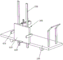
Fig. 1 is a schematic view of the overall structure of the present invention;
fig. 2 is a schematic structural view of the utility model after grabbing the wall board;
fig. 3 is an internal schematic view of the middle fixing housing part of the present invention after being cut open.
The reference numerals in the drawings are explained below.
100. A frame; 200. a guide post; 300. a gripper mechanism; 410. a back plate; 420. a side clamping plate; 430. a base plate; 440. a hook is clamped; 450. a horizontal axis; 510. fixing the shell; 520. a screw rod; 530. a motor; 540. a containing groove; 550. a slider; 560. an extension rod; 600. a rubber block; 700. a wall panel.
Detailed Description
The technical solution of the present invention will be described clearly and completely with reference to the accompanying drawings, and obviously, the described embodiments are some, but not all embodiments of the present invention. Based on the embodiments in the present invention, all other embodiments obtained by a person skilled in the art without creative work belong to the protection scope of the present invention.
In the description of the present invention, it should be noted that the terms "front", "upper", "lower", "left", "right", "vertical", "horizontal", and the like indicate orientations or positional relationships based on the orientations or positional relationships shown in the drawings, and are only for convenience of description and simplification of description, but do not indicate or imply that the device or element referred to must have a specific orientation, be constructed and operated in a specific orientation, and thus, should not be construed as limiting the present invention.
In the description of the present invention, it is to be noted that, unless otherwise explicitly specified or limited, the terms "mounted," "connected," and "connected" are to be construed broadly, and may be, for example, fixedly connected, detachably connected, or integrally connected; they may be connected directly or indirectly through intervening media, or they may be interconnected between two elements. The specific meaning of the above terms in the present invention can be understood in specific cases to those skilled in the art.
As shown in fig. 1 to 3, a wall panel installation apparatus for building finishing includes a frame 100, a guide post 200, and a gripper mechanism 300. The wheels convenient to move are arranged below the frame 100, the guide columns 200 are vertically arranged on one side of the frame 100, the two guide columns 200 are arranged, the gripper mechanisms 300 are arranged on the guide columns 200, and the gripper mechanisms 300 are used for gripping the wall boards 700. And the gripper mechanism 300 is driven by a power device to move the gripper mechanism 300 up and down along the guide post 200, so that the wall plate 700 in the gripper mechanism 300 is moved to a proper height for installation and fixation with other wall plates 700.
The gripper mechanism 300 includes a back plate 410 and side clamping plates 420, and the two side clamping plates 420 are disposed at both sides of the back plate 410. One side of the back plate 410, which is used for contacting the wall plate 700, is a front side, the other opposite side is a back side, a cylinder is arranged on the back side of the back plate 410, and a piston rod of the cylinder is connected with the side clamping plates 420 and used for driving the two side clamping plates 420 to move relatively close to the back plate 410 to clamp the wall plate 700 or move relatively far away from the back plate 410 to put down the wall plate 700. The gripper mechanism 300 is moved to approach the wall plate 700 by moving the carriage 100, then the wall plate 700 is gripped by the driving side clamping plates 420, and the gripper mechanism 300 is lifted off the ground by the power device, so that the wall plate 700 can be moved to the installation destination.
The wall panels 700 are of varying weights and for some heavier wall panels 700, the clamping of the two side clamping plates 420 alone does not hold the wall panel 700. Therefore, the bottom plate 430 is disposed below the back plate 410, and one end of the bottom plate 430, which is far away from the back plate 410, is provided with an inclined surface, which communicates the upper surface and the lower surface of the bottom plate 430, so that the bottom plate 430 contacts the ground, and one side of the inclined surface contacts the ground, and then the wall plate 700 can be shoveled into the gripper mechanism 300 by moving the carriage 100, and in the moving process of the gripper mechanism 300, the bottom plate 430 supports the wall plate 700, so as to increase the weight of the wall plate 700 that the gripper mechanism 300 can grip.
However, when the gripper 300 grips the wall panel 700 during the moving process, the upper end of the wall panel 700 may fall forward due to inertia caused by steering or sudden stop of the frame 100, and the wall panel 700 may be damaged, which causes loss. Therefore, the hook 440 is disposed above the back plate 410, the hook 440 is L-shaped, and the hook 440 has two states, one state is disposed above the back plate 410, and any part of the hook 440 is not present in front of the back plate 410, which does not affect the grabbing mechanism 300 to grab the wall plate 700. In the second state, the hook 440 can rotate 180 degrees along the horizontal axis 450, such that one end of the hook 440 is located right in front of the back plate 410, but when the wall panel 700 falls forward, the upper end of the wall panel 700 will collide against the hook 440 due to the hook 440, thereby preventing the wall panel 700 from being broken.
In order to increase the stability of the wall panel 700 in the moving process, an extension assembly is arranged above the back panel 410, and the hook 440 is arranged on the extension assembly, so that the hook 440 can move in the horizontal direction, and the distance between the hook 440 and the wall panel 700 is adjusted. When the wall panel 700 is thin, the turned hook 440 is adjusted by the extension assembly to make the hook 440 attach to the upper end of the wall panel 700, so that the wall panel 700 is not inclined forward, and the stability of the wall panel 700 in the moving process is increased. The application range of the hook 440 is also expanded, and the hook 440 can be tightly attached to the wall panels 700 with different thicknesses by adjusting the extension assembly, so that the gripper mechanism 300 can be applied to the transportation of the wall panels 700 with different thicknesses.
The extension assembly includes a mounting case 510, a lead screw 520, and a motor 530. The fixing shell 510 is provided with a receiving groove 540 along the length direction thereof, and the receiving groove 540 extends upward to the upper surface of the fixing shell 510. One end of the screw rod 520 is rotatably connected with the inner wall of the fixed mounting shell 510, and the other end of the screw rod is axially connected with the output of the motor 530, and the motor 530 drives the screw rod 520 to rotate. The slider 550 is arranged in the accommodating groove 540, the screw rod 520 penetrates through the middle of the slider 550, the screw rod 520 is in threaded connection with the slider 550, the side wall of the slider 550 is clamped in the accommodating groove 540, and when the screw rod 520 is driven by the motor 530 to rotate, the slider 550 in threaded connection with the screw rod 520 can slide along the screw rod 520. The upper surface of the fixing shell 510 is provided with an extension rod 560, the slider 550 extends upwards and is connected to the lower surface of the extension rod 560, and the hook 440 is rotatably connected to the end of the extension rod 560 through the horizontal shaft 450.
The motor 530 drives the screw rod 520 to rotate, the screw rod 520 drives the slider 550 to move, and the slider 550 drives the extension rod 560 to move, so that the hook 440 moves, and the distance between the hook 440 and the wall panel 700 is adjusted.
The hook 440 is turned 180 degrees around the horizontal shaft 450, one end of the hook can be located right in front of the wall panel 700, and one surface of the hook can contact with the wall panel 700, and the side surface of the hook 440, which contacts with the wall panel 700, is provided with the rubber block 600, and the rubber block 600 contacts with the wall panel 700, so that the wall panel 700 is protected from being scratched by the hook 440.
It should be understood that the above examples are only for clarity of illustration and are not intended to limit the embodiments. Other variations and modifications will be apparent to persons skilled in the art in light of the above description. And are neither required nor exhaustive of all embodiments. And obvious variations or modifications can be made without departing from the scope of the invention.
Claims (6)
1. A wallboard mounting device for building decoration comprises a frame, a guide post vertically arranged on the frame, and a gripper mechanism which slides up and down along the guide post and is used for gripping a wallboard, and is characterized in that the gripper mechanism comprises a back plate and side clamping plates arranged on two sides of the back plate, wherein the back surface of the back plate is provided with a cylinder connected with the side clamping plates and used for controlling the side clamping plates to move close to or far away from the back plate; the wallboard gripping device is characterized in that a clamping hook is arranged above the back plate, the clamping hook is L-shaped, the clamping hook is arranged above the back plate and does not influence the gripping mechanism to grip the wallboard, or the clamping hook rotates 180 degrees along a horizontal shaft, so that one end of the clamping hook is located right ahead of the wallboard and is used for abutting against the wallboard.
2. A wallboard installation device for building decoration according to claim 1 wherein, an extension assembly is provided above said back plate, said hook is provided on the extension assembly, so that the hook can move along the horizontal direction to adjust the distance between the hook and the wallboard.
3. The wallboard mounting device for building decoration according to claim 2, wherein the extension assembly comprises a fixing shell, a screw rod and a motor, a containing groove is formed in the fixing shell, the screw rod is rotatably arranged in the containing groove and connected with an output shaft of the motor, the upper end of the containing groove extends to the surface of the fixing shell, a sliding block is arranged in the containing groove, the screw rod is threaded through the sliding block, an extension rod is arranged on the upper surface of the fixing shell, the sliding block is connected with the extension rod, and the clamping hook is connected with the extension rod through a horizontal shaft.
4. A panel installation apparatus as claimed in claim 3, wherein the lower end of the back panel is provided with a base panel.
5. A wallboard mounting apparatus for building finishing as claimed in claim 4, wherein said bottom plate is inclined at an end away from the back plate, and the inclined surface is connected to the upper and lower surfaces of the bottom plate.
6. A wallboard installation device for building finishing as claimed in claim 1, wherein a rubber block is provided on a surface of said hook contacting with the wallboard.
Priority Applications (1)
| Application Number | Priority Date | Filing Date | Title |
|---|---|---|---|
| CN202020756000.5U CN212201148U (en) | 2020-05-09 | 2020-05-09 | Wallboard installation device for building decoration |
Applications Claiming Priority (1)
| Application Number | Priority Date | Filing Date | Title |
|---|---|---|---|
| CN202020756000.5U CN212201148U (en) | 2020-05-09 | 2020-05-09 | Wallboard installation device for building decoration |
Publications (1)
| Publication Number | Publication Date |
|---|---|
| CN212201148U true CN212201148U (en) | 2020-12-22 |
Family
ID=73813796
Family Applications (1)
| Application Number | Title | Priority Date | Filing Date |
|---|---|---|---|
| CN202020756000.5U Active CN212201148U (en) | 2020-05-09 | 2020-05-09 | Wallboard installation device for building decoration |
Country Status (1)
| Country | Link |
|---|---|
| CN (1) | CN212201148U (en) |
Cited By (1)
| Publication number | Priority date | Publication date | Assignee | Title |
|---|---|---|---|---|
| CN112727119A (en) * | 2020-12-25 | 2021-04-30 | 温州顺启建筑有限公司 | Positioning device for assembly type building |
-
2020
- 2020-05-09 CN CN202020756000.5U patent/CN212201148U/en active Active
Cited By (1)
| Publication number | Priority date | Publication date | Assignee | Title |
|---|---|---|---|---|
| CN112727119A (en) * | 2020-12-25 | 2021-04-30 | 温州顺启建筑有限公司 | Positioning device for assembly type building |
Similar Documents
| Publication | Publication Date | Title |
|---|---|---|
| CN103633375B (en) | A kind of lithium battery electric core process equipment | |
| CN109748104B (en) | Double-station polymer lithium battery feeding method | |
| CN212201148U (en) | Wallboard installation device for building decoration | |
| CN116238910B (en) | Automatic loading and unloading conveyor for stone-like bricks | |
| CN212050398U (en) | Stereoscopic warehouse puts things in good order device | |
| CN113833281B (en) | Intelligent wallboard mounting robot with adjustable mounting range and mounting method | |
| CN212422314U (en) | Paper pushing mechanism for packaging box production line | |
| CN212832615U (en) | Light partition plate mounting equipment | |
| CN111558951B (en) | Soft packet of battery manipulator | |
| CN111573255A (en) | Multi-shaft heavy-load carrying device for automatic logistics system | |
| CN211282833U (en) | Wide electric core carrying mechanism | |
| CN108163527B (en) | Turnover machine for cylindrical lithium battery rotating box | |
| CN219601056U (en) | Indoor multifunctional robot with good stability | |
| CN220056256U (en) | Photovoltaic module lifting device | |
| CN215035065U (en) | Pawl automatic feeding equipment mechanism in pendulum automatic assembly machine | |
| CN220127920U (en) | Connecting piece location extracting device and welding equipment | |
| CN218695415U (en) | Plate positioning tool and plate welding equipment | |
| CN220519525U (en) | Palletizing robot for bagged materials | |
| CN216271747U (en) | Tilting mechanism is used in steel construction processing | |
| CN220578088U (en) | Folding clamping device for warehouse transportation | |
| CN214298295U (en) | Robot stacker crane | |
| CN220165217U (en) | High-efficient high-order stacking machine | |
| CN219096779U (en) | Be provided with assembled building wall body transportation equipment of locking structure | |
| CN220011282U (en) | Pile up neatly device is used in welding of frame net rack climbs | |
| CN218666354U (en) | Electrophoresis application anchor clamps of car battery case |
Legal Events
| Date | Code | Title | Description |
|---|---|---|---|
| GR01 | Patent grant | ||
| GR01 | Patent grant |