CN212128169U - Culture dish holds and culture dish ejecting device - Google Patents
Culture dish holds and culture dish ejecting device Download PDFInfo
- Publication number
- CN212128169U CN212128169U CN202020392323.0U CN202020392323U CN212128169U CN 212128169 U CN212128169 U CN 212128169U CN 202020392323 U CN202020392323 U CN 202020392323U CN 212128169 U CN212128169 U CN 212128169U
- Authority
- CN
- China
- Prior art keywords
- culture dish
- motor
- horizontal
- test tube
- frame
- Prior art date
- Legal status (The legal status is an assumption and is not a legal conclusion. Google has not performed a legal analysis and makes no representation as to the accuracy of the status listed.)
- Active
Links
Images


Abstract
A culture dish containing and culture dish pushing device is characterized in that a culture dish containing mechanism comprises a culture dish containing frame, the culture dish containing frame comprises an upper plate and a lower plate, circular notches are formed in the upper plate and the lower plate, the upper plate and the lower plate vertically correspond to each other, the upper plate and the lower plate are connected through connecting columns, and the upper notch, the lower notch and the connecting columns form a placing cylinder for placing a culture dish; the culture dish ejecting device fixed bolster is fixed to be set up in the frame, first lead screw and culture dish ejecting device fixed bolster swing joint, first vertical migration motor is fixed to be set up on culture dish ejecting device fixed bolster, first vertical migration motor and first rotating gear fixed connection, first rotating gear meshes with first lead screw mutually, the upper end and the first dish fixed connection that pushes away of first lead screw, the diameter of first dish that pushes away is less than the culture dish and holds the circular breach on the frame hypoplastron, culture dish ejecting device can release the culture dish in placing a section of thick bamboo to culture dish and hold the frame upside.
Description
Technical Field
The utility model relates to an inoculation separation and relevant sample pretreatment device of microorganism especially relates to a culture dish holds and culture dish ejecting device.
Background
At present, the microorganism inoculation is accomplished through artifical marking off mode, needs the manual work to take off the sample test tube and vibrate, then manually removes to cover the upper cover and scan the label, to the manual upper cover that removes of culture dish, will manually paste the label after the marking off. The manual scribing has the following defects:
(1) due to factors such as individual level difference, individual habits, randomness of the same person in different time periods and the like, the drawn line is of five-flower eight, the standard is not unified, the inoculation effect is influenced, and the judgment difficulty of doctors is increased. In addition, environmental factors can also have an impact.
(2) The operation efficiency is low, the labor cost is high, and the labor intensity is high.
(3) The operators need to be careful when working, otherwise germs are likely to be stained on hands or splashed on the hands, which causes harm to human health.
SUMMERY OF THE UTILITY MODEL
The utility model aims to solve the problem that compensate above-mentioned prior art's defect, provide a full-automatic culture dish and hold and culture dish ejecting device.
The technical problem of the utility model can be solved through following technical scheme:
a culture dish containing and pushing device comprises a rack, wherein a culture dish containing mechanism is fixedly connected to the rack;
the culture dish containing mechanism comprises a culture dish containing frame, the culture dish containing frame comprises an upper plate and a lower plate, circular notches are formed in the upper plate and the lower plate, the circular notches are vertically corresponding to each other, the upper plate and the lower plate are connected through connecting columns, and the upper notch, the lower notch and the connecting columns form a placing cylinder for placing a culture dish;
the culture dish containing mechanism comprises a culture dish pushing device, the culture dish pushing device comprises a culture dish pushing device fixing support, a first vertical moving motor, a first rotating gear, a first screw rod and a first push disc, the culture dish push-out device fixing bracket is fixedly arranged on the rack, the first screw rod is movably connected with the culture dish push-out device fixing bracket, the first vertical moving motor is fixedly arranged on the culture dish pushing-out device fixing bracket and is fixedly connected with the first rotating gear, the first rotating gear is meshed with the first screw rod, the upper end of the first screw rod is fixedly connected with the first push disc, the diameter of the first push disc is smaller than a circular notch in a lower plate of the culture dish containing frame, and the culture dish pushing device can push out a culture dish in the containing cylinder to the upper side of the culture dish containing frame.
Further, the culture dish holds the mechanism and includes rotating electrical machines, rotating electrical machines install in with in the frame, and with the culture dish holds a transmission and connects, rotating electrical machines drives the culture dish holds a rotation.
Further, the rotating electrical machines includes fixed connection's revolving stage, the revolving stage with the culture dish holds a frame fixed connection, the rotating electrical machines passes through the revolving stage drives to bank up the culture dish holds a frame rotation.
Compared with the prior art, the utility model discloses the beneficial effect who reaches is:
the utility model provides a pair of culture dish holds and culture dish ejecting device, it holds mechanism's rotating electrical machines to be provided with the culture dish in the mechanism to hold at the culture dish, the culture dish holds the frame, culture dish ejecting device, the culture dish through setting holds mechanism's rotating electrical machines and culture dish and holds the frame, can make the culture dish hold the frame and realize rotatory function, culture dish ejecting device through the setting, can release the culture dish and hold the culture dish in the frame, so that the culture dish snatchs the mechanism and snatchs the culture dish, thereby guarantee the automation of device and move, and then guarantee the smoothness nature of device operation.
The utility model provides a pair of culture dish holds and culture dish ejecting device, the rotation of full-automatic completion culture dish and the release operation have improved work efficiency, and the cost is reduced has standardized the sample processing flow of microorganism room, has broken away from the various uncertain factors of artificial existence, has improved the inoculation and has cultivateed the effect.
The utility model provides a pair of culture dish holds and culture dish ejecting device is totally closed operation, and whole process can be accomplished as long as operating personnel touches the computer screen of outside, can realize the infection of completely isolated germ, has eliminated the risk that medical staff infects the germ simultaneously.
Drawings
Fig. 1 is a schematic view of the overall structure of a culture dish containing and pushing device applied to a microorganism sample inoculation device;
FIG. 2 is a schematic view of the overall structure of a device for containing and pushing out a culture dish, which is applied to a microorganism sample inoculating device;
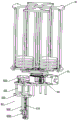
FIG. 3 is a perspective view of the main mechanism of the device for placing and pushing a culture dish of the present invention applied to a device for inoculating a microorganism sample;
FIG. 4 is a top view of the main mechanism of the device for containing and pushing out a culture dish of the present invention applied to a device for inoculating a microorganism sample;
FIG. 5 is a schematic view showing the overall structure of a sample tube gripping mechanism of a microorganism identification and gripping device;
FIG. 6 is a schematic view showing the overall structure of a grasping apparatus of the microorganism identification and grasping apparatus;
FIG. 7 is a schematic view of the entire structure of a sampling mechanism of a microorganism identification and grasping apparatus;
FIG. 8 is a schematic view showing the overall structure of a culture dish holding mechanism of the microorganism identification and grasping apparatus;
FIG. 9 is a schematic view showing the overall structure of a petri dish recovery mechanism of the microorganism identification and grasping device;
FIG. 10 is a schematic view showing the overall structure of a culture dish grasping mechanism of the microorganism identification and grasping apparatus;
FIG. 11 is a schematic view showing the overall structure of a culture dish moving mechanism of the microorganism identification and grasping apparatus;
FIG. 12 is a schematic view showing the overall structure of a bar code device of the microorganism identification and grasping apparatus;
FIG. 13 is a schematic view of the entire structure of a code fetching device of the microorganism identification and grasping device;
FIG. 14 is a schematic view showing the overall structure of a label base paper roll unit of the microorganism identification and grasping apparatus;
FIG. 15 is a schematic view of the entire structure of a petri dish conveying mechanism of the microorganism identification and grasping device.
Reference numbers in the figures:
a rack J, a placing table J1, a storage compartment door J2, a front door J3 and a rear door J4;
placing the plate 1;
a sample tube identification mechanism 2, a tube tray 21, a tube 211, an identification device 22;
the device comprises a sample test tube grabbing mechanism 3, an X-axis device 31, an X-axis motor 311, an X-axis track 312, a Y-axis device 32, a Y-axis motor 321, a Y-axis track 322, an X-axis track connecting part 323, a Z-axis device 33, a Z-axis motor 331, a Z-axis track 332, a Y-axis track connecting part 333, a cover opening and covering device 34, a Z-axis track connecting part 341, a cover screwing device 342, a test tube top rotating motor 343, a clamping device 35, a test tube clamping jaw 351, a test tube clamping electric cylinder 352 and a channel 353;
a scanning device 4, a barcode scanner 41;
the sampler comprises a sampling mechanism 5, a vertical moving device 51, a vertical moving bracket 511, a vertical moving motor 512, a vertical conveying device 513, a vertical moving guide rail 514, a connecting shaft 515, a vertical moving connecting piece 516, a horizontal rotating device 52, a horizontal rotating bracket 521, a horizontal rotating motor 522, a horizontal rotating conveying device 523, a horizontal moving device 53, a horizontal moving bracket 531, a horizontal moving motor 532, a horizontal conveying device 533, a vertical rotating device 54, a vertical rotating motor 541 and an inoculating loop 542;
a sterilization device 6, an infrared sterilizer 61;
a culture dish containing mechanism 7, a culture dish containing mechanism rotating motor 71, a culture dish containing mechanism rotating platform 711, a culture dish containing frame 72, a culture dish push-out device 73, a culture dish push-out device fixing support 730, a first vertical moving motor 731, a first rotating gear 732, a first screw rod 733 and a first push disc 734;
the culture dish recovery mechanism 8, the culture dish recovery mechanism rotating motor 81, the culture dish recovery mechanism rotating platform 811, the culture dish recovery frame 82, the culture dish recovery device 83, the culture dish recovery device fixing support 830, the second vertical moving motor 831, the second lead screw 832, the culture dish recovery device connecting piece 8321, the second push plate 833 and the culture dish recovery device rail 834;
a culture dish gripping mechanism 9, a culture dish vertical moving device 91, a culture dish vertical moving support 911, a culture dish vertical moving motor 912, a culture dish vertical conveying device 913, a culture dish vertical moving guide rail 914, a culture dish connecting shaft 915, a culture dish vertical moving connecting piece 916, a culture dish horizontal rotating device 92, a culture dish horizontal rotating support 921, a culture dish horizontal rotating motor 922, a culture dish horizontal rotating conveying device 923, a culture dish horizontal moving device 93, a culture dish horizontal moving support 931, a culture dish horizontal moving motor 932, a culture dish horizontal conveying device 933, a culture dish clamping device 94, a culture dish clamping electric cylinder 941 and a culture dish clamping claw 942;
the culture dish moving mechanism 10, a culture dish moving mechanism bracket 1000, a horizontal driving motor 1001, a culture dish moving and conveying device 1002, a horizontal synchronous belt connecting frame 1003, a culture dish tray rotating motor 1004, a tray 1005 and a horizontal displacement linear guide rail 1006;
a label pasting mechanism 11, a bar code instrument 1101, a label bracket 11011, a code fetching device 1102, a code fetching device support 11020, a code fetching rotating motor 11021, a label sucking disc 11022, a label backing paper compression roller device 1103, a compression roller device support 11031, a compression roller device motor 11032, a compression roller device driving roller 11033 and a compression roller device driven roller 11034;
the culture dish conveying mechanism 12, the culture dish conveying frame 1200, the culture dish conveying motor 1201, the culture dish conveying connecting piece 1202, the culture dish moving support 1203 and the culture dish recovery part 1204.
Detailed Description
The present invention will be further described below based on preferred embodiments with reference to the accompanying drawings.
In addition, for convenience of understanding, various components on the drawings are enlarged (thick) or reduced (thin), but this is not intended to limit the scope of the present invention.
Singular references also include plural references and vice versa.
In the description of the embodiments of the present invention, it should be noted that, if the terms "upper", "lower", "left", "right", "inner", "outer" and the like indicate the position or positional relationship based on the position or positional relationship shown in the drawings, or the position or positional relationship which is usually placed when the product of the present invention is used, the description is only for convenience of description and simplification, but the indication or suggestion that the device or element to be referred to must have a specific orientation, be constructed and operated in a specific orientation, and thus, should not be interpreted as limiting the present invention. Furthermore, in the description of the present invention, the terms first, second, etc. are used herein to distinguish between different elements, but these should not be limited by the order of manufacture or construed to indicate or imply relative importance, and their names may differ between the detailed description of the invention and the claims.
The words used in this specification are words of description used in describing embodiments of the invention, but are not intended to limit the invention. It is also to be understood that, unless otherwise expressly stated or limited, the terms "disposed," "connected," and "connected" are intended to be open-ended, i.e., may be fixedly connected, detachably connected, or integrally connected; they may be mechanically coupled, directly coupled, indirectly coupled through intervening media, or may be interconnected between two elements. The above-mentioned meaning belonging to the present invention is specifically understood by those skilled in the art.
The utility model provides a microbial sample inoculation device, includes frame J, fixedly connected with sample test tube recognition mechanism 2, sample test tube on the frame J snatch mechanism 3, scanning device 4, sampling mechanism 5, sterilization apparatus 6, culture dish hold mechanism 7, culture dish recovery mechanism 8, culture dish snatch mechanism 9, culture dish moving mechanism 10, label pasting mechanism 11, culture dish conveying mechanism 12 and controller.
As shown in fig. 1, a placing table J1 is horizontally provided in the rack J, and the placing table J1 is used to mount various automatic processing mechanisms. The space below the placing platform J1 is a storage chamber, and the storage chamber is connected with a storage chamber door J2. The space above the placing platform J1 is connected with a front door J3 and a rear door J4, wherein the front door J3 is in sliding connection with the rack J, and the front door J3 can be placed above the inside of the rack J after being pulled open, so that the space is saved. The front door J3 and the rear door J4 can seal the space above the placing table J1 for placing the automatic processing mechanism, isolate the germ pollution in the sample processing process and prevent operators from infecting the germ. The front door J3 and the rear door J4 may be made of a transparent material such as glass, plastic, or the like.
A microorganism sample inoculation device comprises a placing plate 1, various automatic processing mechanisms are fixedly connected to the placing plate 1, and the placing plate 1 is fixedly arranged on a placing platform J1.
Sample test tube recognition mechanism 2 includes test tube tray 21 and recognition device 22, test tube tray 21 is fixed to be set up on placing board 1, be equipped with a plurality of test tube groove on the test tube tray 21, 28 test tubes 211 that are equipped with the sample have been placed in the test tube groove, recognition device 22 is fixed to be set up in the inside top of frame J, and be located same plumb line with test tube tray 21, recognition device 22 is connected with the controller electricity, a test tube 211 for on the discernment test tube tray 21 test tube inslot, and transmit the result to the controller, so that the controller control sample test tube snatchs mechanism 3 according to recognition device 22's identification result, snatch the test tube groove that has test tube 211 on the test tube tray 21, carry out operation on next step.
The sample test tube gripping mechanism 3 is fixedly arranged on the placing plate 1 and located on the left side of the sample test tube identification mechanism 2 and comprises an X-axis device 31, a Y-axis device 32, a Z-axis device 33, a cap opening and covering device 34 and a clamping device 35, wherein the Y-axis device 32 is movably connected with the X-axis device 31 and moves on the X-axis device 31 along the X axis, the Z-axis device 33 is movably connected with the Y-axis device 32 and moves on the Y-axis device 32 along the Y axis, the cap opening and covering device 34 is movably connected with the Z-axis device 33 and moves on the Z-axis device 33 along the Z axis, the cap opening and covering device 34 is used for gripping the test tube 211 and moving to a position which is located on the same vertical line with the clamping device 35, the clamping device 35 is used for clamping the bottom of the test tube 211, and at the moment, the cap opening and covering device 34 rotates to realize the cap opening and.
Specifically, the X-axis device 31 includes an X-axis motor 311 and an X-axis rail 312, the Y-axis device 32 includes a Y-axis motor 321, a Y-axis rail 322, and an X-axis rail connection part 323, the Z-axis device 33 includes a Z-axis motor 331, a Z-axis rail 332, and a Y-axis rail connection part 333, and the uncapping upper cover device 34 includes a Z-axis rail connection part 341; the X-axis track connecting part 323 is movably connected with the X-axis track 312, and when the X-axis motor 311 operates, the X-axis track connecting part 323 can drive a screw rod connected with the X-axis motor 311 to rotate, so as to drive the X-axis track connecting part 323 to move on the X-axis track 312 along the X axis, and finally drive the Y-axis device 32 to move on the X-axis device 31 along the X axis; the Y-axis rail connection part 333 is movably connected to the Y-axis rail 322, and when the Y-axis motor 321 operates, the Y-axis rail connection part 333 drives a lead screw connected to the Y-axis motor 321 to rotate, so as to drive the Y-axis rail connection part 333 to move along the Y-axis on the Y-axis rail 322, and finally drive the Z-axis device 33 to move along the Y-axis on the Y-axis device 32; the Z-axis track connection portion 341 is movably connected to the Z-axis track 332, and when the Z-axis motor 331 operates, the screw rod connected to the Z-axis motor 331 is driven to rotate, so as to drive the Z-axis track connection portion 341 to move along the Z-axis on the Z-axis track 332, and finally drive the cover opening and covering device 34 to move along the Z-axis on the Z-axis device 33.
The cap opening and covering device 34 comprises a cap screwing device 342 and a test tube top rotating motor 343 which are fixedly connected, the clamping device 35 comprises a test tube clamping jaw 351 and a test tube clamping electric cylinder 352, the test tube top rotating motor 343 is fixedly connected with the cap screwing device 342, and the cap screwing device 342 is driven to rotate when the test tube top rotating motor 343 operates; the clamping device 35 is fixedly arranged on the placing plate 1 and arranged above the test tube tray 21, the test tube clamping jaw 351 and the test tube clamping electric cylinder 352 are fixedly connected with each other, and the test tube clamping electric cylinder 352 can drive the test tube clamping jaw 351 to move when in operation; during the use, uncap upper cover device 34 and remove to the top of test tube tray 21, and move down along the Z axle, spiral cover ware 342 cliies test tube 211, and move test tube 211 to the position of getting device 35 and lieing in same perpendicular line with the clamp, test tube centre gripping electricity jar 352 control test tube clamping jaw 351 cliies the bottom of test tube 211, at this moment, test tube top rotating electrical machines 343 drive spiral cover ware 342 and operate and rotate, open or tighten the upper cover of test tube 211, the sampling mechanism 5 of can being convenient for when opening samples, can restore the original state with test tube 211 after tightening.
Press from both sides and get device 35 and include passageway 353, passageway 353 sets up fixedly on placing board 1, and be located same vertical line with test tube clamping jaw 351, passageway 353 runs through and places board 1, it connects two spaces about placing board 1, namely, the top of passageway 353 is for placing the space of board 1 top, the below of passageway 353 is the storing room, be provided with the recycling bin with passageway 353 position department on same vertical line in the storing room, after pressing from both sides the test tube 211 that gets device 35 clamp and accomplish sample and the upper cover operation, test tube centre gripping electric cylinder 352 operation control test tube clamping jaw 351 removes, thereby carry test tube 211 to the recycling bin in the storing room along passageway 353, concentrate the recovery with the test tube 211 of taking a sample.
The scanning device 4 is fixedly disposed on the placing plate 1 and disposed on the right side of the sample test tube recognition mechanism 2, preferably, the scanning device 4 is a bar code scanner 41, and is connected to the controller for scanning a bar code on the test tube 211.
Specifically, the vertical moving device 51 comprises a vertical moving bracket 511, a vertical moving motor 512, a vertical conveying device 513, a vertical moving guide rail 514, a connecting shaft 515 and a vertical moving connecting piece 516, the horizontal rotating device 52 comprises a horizontal rotating bracket 521, a horizontal rotating motor 522 and a horizontal rotating conveying device 523, the horizontal moving device 53 comprises a horizontal moving bracket 531, a horizontal moving motor 532 and a horizontal conveying device 533, and the vertical rotating device 54 comprises a vertical rotating motor 541 and an inoculating loop 542; the vertical moving support 511 is fixedly arranged on the placing plate 1, the vertical moving motor 512 is fixedly arranged on the vertical moving support 511, the vertical conveying device 513 is movably connected with the vertical moving motor 512, when the vertical moving motor 512 operates, the vertical conveying device 513 can be driven to move, the vertical moving guide rail 514 is fixedly arranged on the vertical moving support 511, one end of the connecting shaft 515 is provided with a vertical moving connecting piece 516, the vertical moving connecting piece 516 is movably connected with the vertical moving guide rail 514 and moves on the vertical moving guide rail 514, when the vertical moving motor 512 operates, the vertical conveying device 513 can be driven to move, and the connecting shaft 515 is driven to move up and down along the vertical moving guide rail 514 through the vertical moving connecting piece 516.
The horizontal rotation bracket 521 is fixedly arranged on the upper side of the vertical moving bracket 511, the horizontal rotation motor 522 is fixedly arranged on the horizontal rotation bracket 521, the horizontal rotation conveying device 523 is movably connected with the horizontal rotation motor 522, the horizontal rotation conveying device 523 is fixedly connected with the connecting shaft 515, and when the horizontal rotation motor 522 operates, the horizontal rotation conveying device 523 can be driven to move so as to drive the connecting shaft 515 to rotate horizontally.
The horizontal moving bracket 531 is fixedly disposed on the upper side of the connecting shaft 515, and is fixedly connected to the connecting shaft 515, the horizontal moving motor 532 is fixedly disposed on the horizontal moving bracket 531, the horizontal conveying device 533 is movably connected to the horizontal moving motor 532, and when the horizontal moving motor 532 operates, the horizontal conveying device 533 can be driven to move.
Vertical rotating electrical machines 541 sets up in the one end of horizontal migration support 531 fixedly, transfering loop 542 and vertical rotating electrical machines 541 fixed connection, can drive transfering loop 542 vertical rotation when vertical rotating electrical machines 541 operates, can drive horizontal transfer device 533 when horizontal migration motor 532 operates and move, and then drive vertical rotary device 54 horizontal migration.
The culture dish holds mechanism 7 and culture dish recovery mechanism 8 and all fixes and set up on placing board 1, culture dish holds mechanism 7 and sets up the right side at sample test tube recognition mechanism 2, culture dish recovery mechanism 8 sets up the right side that holds mechanism 7 at the culture dish, culture dish holds mechanism 7 and includes that rotating electrical machines 71 and culture dish hold frame 72, culture dish recovery mechanism 8 includes rotating electrical machines 81 and culture dish recovery frame 82, culture dish holds frame 72 and culture dish recovery frame 82 and is connected with rotating electrical machines 71 and rotating electrical machines 81 transmission respectively, rotating electrical machines 71 can drive the culture dish and hold frame 72 and rotate, rotating electrical machines 81 can drive culture dish recovery frame 82 and rotate.
Preferably, the rotating motor 71 includes a fixedly connected rotating platform 711, the rotating motor 81 includes a fixedly connected rotating platform 811, the rotating platform 711 is fixedly connected with the culture dish containing rack 72, the rotating platform 811 is fixedly connected with the culture dish retrieving rack 82, the rotating motor 71 can drive the culture dish containing rack 72 to rotate through the rotating platform 711, and the rotating motor 81 can drive the culture dish retrieving rack 82 to rotate through the rotating platform 811.
The culture dish holding frame 72 and the culture dish recycling frame 82 are both provided with a plurality of culture dish holding cylinders, the structures of the culture dish holding frame 72 and the culture dish recycling frame 82 are similar, and the description is given by taking the structure of the culture dish holding frame 72 as an example.
Preferably, the dish holding rack 72 is provided with six dish holding cylinders, and the dish recycling rack 82 is provided with four dish holding cylinders.
The culture dish containing frame 72 comprises an upper plate with a circular notch and a lower plate with a circular notch, the circular notches on the upper plate and the lower plate are vertically corresponding to each other, the upper plate and the lower plate are connected through a connecting column, and the upper notch, the lower notch and the connecting column form a containing cylinder for containing the culture dish.
The culture dish holding mechanism 7 comprises a culture dish push-out device 73 for pushing out the culture dish in the placing cylinder, so that the culture dish grabbing mechanism 9 grabs the culture dish to the culture dish moving mechanism 10. The culture dish pushing device 73 comprises a culture dish pushing device fixing support 730, a first vertical moving motor 731, a first rotating gear 732, a first screw rod 733 and a first pushing disc 734, wherein the culture dish pushing device fixing support 730 is fixedly arranged on the lower side of the placing plate 1, the first screw rod 733 is movably connected with the culture dish pushing device fixing support 730, the first vertical moving motor 731 is fixedly arranged on the culture dish pushing device fixing support 730 and is fixedly connected with the first rotating gear 732, the first rotating gear 732 is meshed with the first screw rod 733, the upper end of the first screw rod 733 is fixedly connected with the first pushing disc 734, and the diameter of the first pushing disc 734 is smaller than a circular notch on the lower plate of the culture dish containing frame 72; when the first vertical moving motor 731 is operated, the first rotating gear 732 can be driven to rotate, and then the first lead screw 733 is driven to move up and down, so that the first push plate 734 moves up and down, the first push plate 734 pushes out the culture dish in the placing cylinder to the upper side of the culture dish containing frame 72 through the circular notch on the lower plate of the culture dish containing frame 72, and the culture dish grabbing mechanism 9 grabs the culture dish.
The culture dish recovery mechanism 8 comprises a culture dish recovery device 83 for moving the culture dish in the placing cylinder so that the culture dish is recovered by the culture dish recovery mechanism 8. The culture dish recovery device 83 comprises a culture dish recovery device fixing support 830, a second vertical moving motor 831, a second screw 832, a second push disc 833 and a culture dish recovery device track 834, wherein the culture dish recovery device fixing support 830 is fixedly arranged on the upper side of the placing plate 1, the second vertical moving motor 831 is fixedly arranged on the culture dish recovery device fixing support 830 and is fixedly connected with the second screw 832, the culture dish recovery device track 834 is fixedly arranged on the culture dish recovery device fixing support 830, one end of the second screw 832 is provided with a culture dish recovery device connecting piece 8321, the culture dish recovery device connecting piece 8321 is movably connected with the culture dish recovery device track 834, the other end of the second screw 832 is provided with a second push disc 833, and the diameter of the second push disc 833 is smaller than a circular notch on the lower plate of the culture dish recovery frame 82; when the second vertical movement motor 831 operates, it can drive the second lead screw 832 to move up and down, and then drive the connecting piece 8321 of the culture dish recycling device to move on the track 834 of the culture dish recycling device, so that the second pushing plate 833 moves up and down, the second pushing plate 833 moves up and down through the circular notch on the lower plate of the culture dish recycling frame 82, the culture dish in the placing cylinder moves up and down, and the culture dish is recycled by the culture dish recycling mechanism 8.
The culture dish grabbing mechanism 9 is fixedly arranged on the placing plate 1 and is arranged on the upper side of the culture dish recycling mechanism 8, the culture dish grabbing mechanism 9 comprises a culture dish vertical moving device 91, a culture dish horizontal rotating device 92, a culture dish horizontal moving device 93 and a culture dish clamping device 94, the culture dish horizontal rotating device 92 is arranged on the upper side of the culture dish vertical moving device 91, the culture dish horizontal rotating device 92 is fixedly connected with the culture dish vertical moving device 91, the culture dish vertical moving device 91 comprises a culture dish connecting shaft 915, the culture dish horizontal moving device 93 is arranged on the culture dish horizontal rotating device 92 and is fixedly connected with a culture dish connecting shaft 915, the culture dish vertical moving device 91 drives the culture dish horizontal moving device 93 to move up and down through the culture dish 915, the culture dish horizontal rotating device 92 drives the culture dish horizontal moving device 93 to horizontally rotate through the culture dish connecting shaft 915, the culture dish clamping device 94 is arranged on the culture dish horizontal moving device 93, and the culture dish horizontal moving device 93 drives the culture dish clamping device 94 to move horizontally.
Specifically, the culture dish vertical moving device 91 includes a culture dish vertical moving support 911, a culture dish vertical moving motor 912, a culture dish vertical conveying device 913, a culture dish vertical moving guide 914, a culture dish connecting shaft 915, and a culture dish vertical moving connecting piece 916, the culture dish horizontal rotating device 92 includes a culture dish horizontal rotating support 921, a culture dish horizontal rotating motor 922, and a culture dish horizontal rotating conveying device 923, the culture dish horizontal moving device 93 includes a culture dish horizontal moving support 931, a culture dish horizontal moving motor 932, and a culture dish horizontal conveying device 933, and the culture dish clamping device 94 includes a culture dish clamping electric cylinder 941 and a culture dish clamping claw 942; a culture dish vertical moving bracket 911 is fixedly arranged on the placing plate 1, a culture dish vertical moving motor 912 is fixedly arranged on the culture dish vertical moving bracket 911, a culture dish vertical conveying device 913 is movably connected with the culture dish vertical moving motor 912, when the culture dish vertical moving motor 912 operates, the culture dish vertical conveying device 913 can be driven to move, the culture dish vertical moving guide rail 914 is fixedly arranged on the culture dish vertical moving support 911, one end of the culture dish connecting shaft 915 is provided with a culture dish vertical moving connecting piece 916, the culture dish vertical moving connecting piece 916 is movably connected with the culture dish vertical moving guide rail 914 and moves on the culture dish vertical moving guide rail 914, when the culture dish vertical moving motor 912 operates, the culture dish vertical conveying device 913 can be driven to move, and the culture dish connecting shaft 915 is driven by the culture dish vertical moving connecting piece 916 to move up and down along the culture dish vertical moving guide rail 914.
Culture dish horizontal rotation support 921 is fixed to be set up in the upside of culture dish vertical movement support 911, culture dish horizontal rotation motor 922 is fixed to be set up on culture dish horizontal rotation support 921, culture dish horizontal rotation conveyer 923 and culture dish horizontal rotation motor 922 swing joint, culture dish horizontal rotation conveyer 923 and culture dish connecting axle 915 fixed connection, can drive culture dish horizontal rotation conveyer 923 motion when culture dish horizontal rotation motor 922 functions, and then drive culture dish connecting axle 915 and carry out the horizontal rotation.
Culture dish horizontal migration support 931 is fixed to be set up in the upside of culture dish connecting axle 915 to with culture dish connecting axle 915 fixed connection, culture dish horizontal migration motor 932 is fixed to be set up on culture dish horizontal migration support 931, culture dish horizontal transport device 933 and culture dish horizontal migration motor 932 swing joint, can drive culture dish horizontal transport device 933 motion when culture dish horizontal migration motor 932 operates.
The fixed one end that sets up in culture dish horizontal migration support 931 of electric jar 941 is got to the culture dish clamp, and electric jar 941 fixed connection is got to culture dish clamping jaw 942 and culture dish clamp, can drive culture dish clamping jaw 942 when electric jar 941 function is got to the culture dish clamp and open or closed motion, and then gets the culture dish, can drive the motion of culture dish horizontal transfer device 933 when culture dish horizontal migration motor 932 functions, and then drives the culture dish clamp and get device 94 horizontal migration.
The culture dish moving mechanism 10 is fixedly arranged on the placing plate 1, is arranged on the left side of the sampling mechanism 5, and comprises a culture dish moving mechanism bracket 1000, a horizontal driving motor 1001, a culture dish moving and conveying device 1002, a horizontal synchronous belt connecting frame 1003, a culture dish tray rotating motor 1004, a tray 1005 and a horizontal displacement linear guide rail 1006; culture dish moving mechanism support 1000 is fixed to be set up on placing board 1, horizontal driving motor 1001 and culture dish moving mechanism support 1000 fixed connection, culture dish removes conveyer 1002 and horizontal driving motor 1001's output shaft, horizontal synchronous belt link 1003 and culture dish remove conveyer 1002 fixed connection, culture dish tray rotating electrical machines 1004 installs on horizontal synchronous belt link 1003, horizontal displacement linear guide 1006 installs on culture dish moving mechanism support 1000, horizontal synchronous belt link 1003 is connected with horizontal displacement linear guide 1006 and is matchd, culture dish tray rotating electrical machines 1004 is connected with tray 1005 hub connection.
The culture dish is clamped on the tray 1005, the culture dish tray rotating motor 1004 drives the tray 1005 to rotate, and then the tray 1005 drives the culture dish to rotate. Horizontal driving motor 1001 moves and drives the motion of culture dish removal conveyer 1002, and then drives horizontal hold-in range link 1003 and be linear motion along horizontal displacement linear guide 1006, and culture dish removal conveyer 1002 is used for conveying power for horizontal hold-in range link 1003 drives tray 1005 and is linear motion, and tray 1005 drives the culture dish and makes linear motion, realizes that the culture dish moves steadily, accurately in the space.
The label pasting mechanism 11 is fixedly arranged on the placing plate 1, and is arranged on the right side of the culture dish grabbing mechanism 9, the label pasting mechanism 11 comprises a bar code instrument 1101, a code fetching device 1102, a label backing paper pressing roller device 1103, the bar code instrument 1101 is fixedly arranged above the culture dish recycling mechanism 8, a bar code label is placed in the bar code instrument 1101, the code fetching device 1102 is arranged on the lower side of the bar code instrument 1101 and is used for fetching a label in the bar code instrument 1101, the culture dish grabbing mechanism 9 is convenient to grab the culture dish and paste the label, the label backing paper pressing roller device 1103 is fixedly arranged below the bar code instrument 1101 and is used for guiding the label backing paper in the bar code instrument 1101 to a storage room below the placing table J1, and the neatness on the placing plate 1.
Specifically, the barcode instrument 1101 is an existing printer, a label holder 11011 is provided at an outlet of the barcode instrument 1101, and printed labels are output to the label holder 11011, so that the labels are prevented from falling off when being sent out.
Get yard device 1102 including getting yard device support 11020, get yard rotating electrical machines 11021 and sucking mark dish 11022, get yard device support 11020 and fix and set up on placing board 1, get yard rotating electrical machines 11021 and get yard device support 11020 fixed connection, sucking mark dish 11022 is connected with the output shaft of getting yard rotating electrical machines 11021, can drive sucking mark dish 11022 when getting yard rotating electrical machines 11021 and operating and rotate, sucking mark dish 11022 can absorb the label on label bracket 11011, be convenient for the culture dish snatch mechanism 9 and snatch the culture dish and paste bar code label.
The label backing paper pressing roller device 1103 is fixedly arranged on the placing plate 1 and arranged at the lower side of the bar code instrument 1101, the label backing paper pressing roller device 1103 comprises a pressing roller device bracket 11031, a pressing roller device motor 11032, a pressing roller device driving roller 11033 and a pressing roller device driven roller 11034, the pressing roller device bracket 11031 is fixedly arranged on the placing plate 1, the pressing roller device motor 11032 is fixedly connected with the pressing roller device bracket 11031, the pressing roller device driving roller 11033 is arranged on the output end of the pressing roller device motor 11032, the pressing roller device driven roller 11034 is fixedly connected on the pressing roller device bracket 11031 and is contacted with the pressing roller device driving roller 11033, when the motor 11032 of the compression roller device operates, the driving roller 11033 of the compression roller device can be driven to operate, and then the driven roller 11034 of the compression roller device is driven to operate, and finally the label base paper between the driving roller 11033 of the compression roller device and the driven roller 11034 of the compression roller device is guided to the storage room under the placing platform J1, so that the neatness of the placing plate 1 is kept.
The culture dish conveying mechanism 12 is fixedly arranged on the placing plate 1 and is arranged between the label sticking mechanism 11 and the culture dish recovery mechanism 8, the culture dish conveying mechanism 12 comprises a culture dish conveying frame 1200, a culture dish conveying motor 1201, a culture dish conveying connecting piece 1202, a culture dish moving support 1203 and a culture dish recovery part 1204, the culture dish conveying frame 1200 is fixedly arranged on the placing plate 1, the culture dish conveying motor 1201 is fixedly arranged on the culture dish conveying frame 1200, the culture dish conveying connecting piece 1202 is arranged on an output shaft of the culture dish conveying motor 1201, the culture dish moving support 1203 is fixedly arranged on the culture dish conveying frame 1200, the culture dish recovery part 1204 is arranged at one end of the culture dish moving support 1203, the culture dish conveying connecting piece 1202 can move in the middle of the culture dish moving support 1203, when in use, when the culture dish is placed on the culture dish moving support 1203 by the culture dish grabbing mechanism 9, the culture dish conveying motor 1201 starts to operate, the culture dish conveying connecting part 1202 moves on the culture dish moving support 1203, the culture dish is further driven to move to the culture dish recovery part 1204, and at the moment, the culture dish recovery device 83 moves to convey the culture dish of the culture dish recovery part 1204 to the culture dish recovery frame 82.
The motors and the electric cylinders are respectively connected with the controller and controlled by a PCI bus, and a human-computer interaction operation panel connected with the controller is arranged on the rack J, preferably, the human-computer interaction operation panel can be a touch liquid crystal screen.
The operation of a microbial sample inoculation device is described further below.
The test tube 211 (with a lid) containing the sample is placed in the test tube well of the test tube tray 21, and simultaneously a corresponding number of petri dishes with agar are placed in the placing cylinder of the petri dish holding rack 72, and then the run button on the operation panel is clicked.
The recognition device 22 performs recognition processing on the test tube 211 placed on the test tube tray 21, so that the sample test tube gripping mechanism 3 can accurately grip the test tube 211.
The X-axis device 31, the Y-axis device 32, and the Z-axis device 33 cooperate with each other such that the cap-opening and covering device 34 is translated to the test tube tray 21, the cap-screwing device 342 moves downward to descend to the test tube 211 of the test tube tray 21 and clamp the test tube 211, and the cap-screwing device 342 moves upward by a distance to take out the test tube 211 in the test tube slot.
The cap screwing device 342 moves to the upper side of the clamping device 35, the rotating motor 343 at the top of the test tube drives the cap screwing device 342 to rotate, the test tube 211 is driven to rotate synchronously, and at the moment, the bar code scanner 41 scans the bar code on the test tube 211.
The cap screwing device 342 moves downwards to the clamping device 35, the test tube clamping electric cylinder 352 controls the test tube clamping jaw 351 to clamp the bottom of the test tube 211, then the test tube top rotating motor 343 drives the cap screwing device 342 to rotate to open the cover of the test tube 211, the cap opening and covering device 34 moves to the test tube tray 21, a space is provided for the sampling mechanism 5 to sample, and the test tube clamping electric cylinder 352 clamps the test tube with the cover removed.
After the sample is accomplished, the spiral cover ware 342 moves to getting device 35 department again, and spiral cover ware 342 moves down and makes the spiral cover ware 342 that has the test tube lid move down to getting device 35 department, and test tube top rotating electrical machines 343 drive spiral cover ware 342 rotation makes the test tube lid screw on the test tube, has covered the lid of test tube 211, then test tube clamping electric cylinder 352 control test tube clamping jaw 351 loosens test tube 211, and test tube 211 then falls into along passageway 353 and places in the indoor recycling bin of storing under platform J1.
The rotating motor 71 drives the culture dish containing frame 72 to rotate to a proper position, and the culture dish pushing device 73 pushes out the culture dish in the placing cylinder to the top of the culture dish containing frame 72, so that the culture dish grabbing mechanism 9 grabs the culture dish.
The culture dish is placed on the culture dish moving mechanism 10 by the culture dish grabbing mechanism 9, then the cover of the culture dish is opened by the culture dish grabbing mechanism 9, so that the sampling mechanism 5 is matched with the culture dish moving mechanism 10 to inoculate microorganisms.
It should be noted that the present invention does not limit the number of the inoculating loop on the inoculating loop 542, and there may be two, three or four, and all the mechanical structures that use the present invention to realize the movement of the inoculating loop 542 all fall into the protection scope of the present invention.
After the lineation treatment is completed, the culture dish grabbing mechanism 9 with the culture dish cover moves to the upper portion of the culture dish with the line drawn on the culture dish moving mechanism 10, the cover of the culture dish covers back to the upper portion of the inoculated culture dish, then the whole culture dish is taken up and moved to the label pasting mechanism 11, and the label pasting treatment is carried out.
The barcode instrument 1101 operates to output barcode labels with the same content as the barcodes on the uncapped test tubes to the label bracket 11011, the code taking rotary motor 11021 rotates a certain angle from the initial position to drive the label sucking disc 11022 to move to the upper side of the label bracket 11011, the code taking rotary motor 11021 moves downwards to enable the label sucking disc 11022 to be attached to the labels on the label bracket 11011, then the code taking rotary motor 11021 rotates to move the label sucking disc 11022 to the position where the labels are upward, at the moment, the culture dish grabbing mechanism 9 moves the culture dish downwards to the label sucking disc 11022, and the labels on the label sucking disc 11022 are adhered to the culture dish.
The culture dish grabbing mechanism 9 places the culture dish on the culture dish moving support 1203, the culture dish conveying motor 1201 drives the culture dish conveying connecting piece 1202 to operate, and then the culture dish is moved to the culture dish recovery part 1204 on the culture dish moving support 1203.
The culture dish recovery device 83 moves to convey the culture dishes at the culture dish recovery part 1204 to the culture dish recovery rack 82, and the culture dish recovery work is completed.
To this end, the first sample tube on the tube tray 21 has been processed, and the process is repeated for the second sample tube.
When a culture dish of the culture dish holding frame 72 holds a culture dish in the cylinder and is processed, the culture dish is pushed out by the culture dish pushing device 73 arranged below the culture dish holding cylinder, so that the culture dish is grabbed by the culture dish grabbing mechanism 9. The culture dish recovery device 83 of the culture dish recovery mechanism 8 can facilitate the recovery of the culture dishes at the culture dish recovery part 1204, and convey the culture dishes to the culture dish recovery rack 82.
After the whole process is finished, an audible and visual alarm device connected with the controller prompts an alarm, and then an operator opens the front door J3 to take out a sample test tube and a culture dish.
The detailed description of the embodiments of the present invention has been presented above, and it will be apparent to those skilled in the art that the present invention can be modified and improved without departing from the principles of the present invention, and the modifications and improvements also belong to the protection scope of the claims of the present invention.
Claims (3)
1. The utility model provides a culture dish holds and culture dish ejecting device which characterized in that: the culture dish placing machine comprises a machine frame (J), wherein a culture dish placing mechanism (7) is fixedly connected to the machine frame (J);
the culture dish containing mechanism (7) comprises a culture dish containing frame (72), the culture dish containing frame (72) comprises an upper plate and a lower plate, circular notches are formed in the upper plate and the lower plate, the circular notches are vertically corresponding to each other, the upper plate and the lower plate are connected through connecting columns, and the upper notch, the lower notch and the connecting columns form a placing cylinder for placing a culture dish;
the culture dish containing mechanism (7) comprises a culture dish pushing-out device (73), the culture dish pushing-out device (73) comprises a culture dish pushing-out device fixing support (730), a first vertical moving motor (731), a first rotating gear (732), a first lead screw (733) and a first push disc (734), the culture dish pushing-out device fixing support (730) is fixedly arranged on the rack (J), the first lead screw (733) is movably connected with the culture dish pushing-out device fixing support (730), the first vertical moving motor (731) is fixedly arranged on the culture dish pushing-out device fixing support (730), the first vertical moving motor (731) is fixedly connected with the first rotating gear (732), the first rotating gear (732) is meshed with the first lead screw (733), the upper end of the first lead screw (733) is fixedly connected with the first push disc (734), the diameter of the first push disc (734) is smaller than the circular notch on the lower plate of the culture dish containing frame (72), and the culture dish push-out device (73) can push out the culture dish in the placing cylinder to the upper side of the culture dish containing frame (72).
2. A culture dish holding and pushing device according to claim 1, wherein the culture dish holding mechanism (7) comprises a rotating motor (71), the rotating motor (71) is mounted on the frame (J) and is in transmission connection with the culture dish holding rack (72), and the rotating motor (71) drives the culture dish holding rack (72) to rotate.
3. A culture dish holding and pushing device according to claim 2, wherein the rotating motor (71) comprises a fixedly connected rotating platform (711), the rotating platform (711) is fixedly connected with the culture dish holding rack (72), and the rotating motor (71) drives the culture dish holding rack (72) to rotate through the rotating platform (711).
Priority Applications (1)
| Application Number | Priority Date | Filing Date | Title |
|---|---|---|---|
| CN202020392323.0U CN212128169U (en) | 2020-03-25 | 2020-03-25 | Culture dish holds and culture dish ejecting device |
Applications Claiming Priority (1)
| Application Number | Priority Date | Filing Date | Title |
|---|---|---|---|
| CN202020392323.0U CN212128169U (en) | 2020-03-25 | 2020-03-25 | Culture dish holds and culture dish ejecting device |
Publications (1)
| Publication Number | Publication Date |
|---|---|
| CN212128169U true CN212128169U (en) | 2020-12-11 |
Family
ID=73671663
Family Applications (1)
| Application Number | Title | Priority Date | Filing Date |
|---|---|---|---|
| CN202020392323.0U Active CN212128169U (en) | 2020-03-25 | 2020-03-25 | Culture dish holds and culture dish ejecting device |
Country Status (1)
| Country | Link |
|---|---|
| CN (1) | CN212128169U (en) |
-
2020
- 2020-03-25 CN CN202020392323.0U patent/CN212128169U/en active Active
Similar Documents
| Publication | Publication Date | Title |
|---|---|---|
| CN111286458A (en) | Microbial sample inoculation device | |
| CN104403938B (en) | Micro-biological samples processes intelligent robot | |
| CN104444983B (en) | Sample tube goes to close the lid and Handling device automatically | |
| CN212610640U (en) | Microbial sample inoculation device | |
| TW201900361A (en) | Automatic medication dispensing device | |
| CN204264558U (en) | Automatic labelling apparatus | |
| CN108048302B (en) | Full-automatic nucleic acid extractor | |
| CN111551756A (en) | Full-automatic film-making dyeing scanning system | |
| CN110484437A (en) | A kind of high-effective microorganism system for pretreating sample | |
| CN109342140A (en) | A kind of high-effective microorganism system for pretreating sample | |
| CN211595640U (en) | High-efficient little biological sample pretreatment system | |
| CN108795730A (en) | A kind of automatic flat-plate inoculation instrument | |
| CN115895894A (en) | Cell culture equipment | |
| JP2014064518A (en) | Automatic bacteriological examination device and method | |
| CN204251608U (en) | The automatic rocking equipment of sample tube | |
| CN115058325A (en) | Automatic microorganism workstation and working method thereof | |
| CN212128169U (en) | Culture dish holds and culture dish ejecting device | |
| CN212126738U (en) | Microorganism identification and grabbing device | |
| CN204251623U (en) | Micro-biological samples process intelligent robot | |
| CN113249208B (en) | Blood sample culture detection workstation | |
| CN112662538A (en) | Microbial sample pretreatment system | |
| US20010053335A1 (en) | Automatic testing apparatus | |
| CN204251298U (en) | Sample tube goes to close the lid and Handling device automatically | |
| CN111551417A (en) | Automatic film making device | |
| CN214694163U (en) | Microbial sample pretreatment system |
Legal Events
| Date | Code | Title | Description |
|---|---|---|---|
| GR01 | Patent grant | ||
| GR01 | Patent grant |