CN212069182U - Spiral dust collecting device - Google Patents
Spiral dust collecting device Download PDFInfo
- Publication number
- CN212069182U CN212069182U CN202020222597.5U CN202020222597U CN212069182U CN 212069182 U CN212069182 U CN 212069182U CN 202020222597 U CN202020222597 U CN 202020222597U CN 212069182 U CN212069182 U CN 212069182U
- Authority
- CN
- China
- Prior art keywords
- dust collecting
- dust
- collecting cylinder
- spiral
- main shaft
- Prior art date
- Legal status (The legal status is an assumption and is not a legal conclusion. Google has not performed a legal analysis and makes no representation as to the accuracy of the status listed.)
- Active
Links
Images


Landscapes
- Separating Particles In Gases By Inertia (AREA)
Abstract
The utility model discloses a spiral dust collecting device, which comprises a device body, wherein the device body comprises a dust collecting cylinder, and the dust collecting cylinder is a cone; the upper part of the dust collecting cylinder is provided with an air inlet, and the lower part of the dust collecting cylinder is provided with an air outlet; the top end of the dust collecting cylinder is provided with a motor; the middle part of the dust collecting cylinder is vertically provided with a main shaft; a spiral channel is correspondingly arranged outside the main shaft; the bottom of the spiral channel is connected with the discharge port; the bottom of the discharge opening is provided with an air lock; the spiral channel comprises a spiral blade spirally connected to the outer side of the main shaft; the side surface of the periphery of the spiral blade, which is far away from the main shaft, is upwards provided with a material baffle plate; a plurality of scraping brushes are arranged on the outer wall of the material baffle at intervals; the scraping brushes are distributed at equal intervals; the scraping brushes are all attached to the inner wall of the dust collecting cylinder. The utility model discloses not only avoided tiny dust to discharge from the air outlet, dust removal effect is good, efficient, and the dust exhaust is effectual moreover, and the dust is difficult to pile up, and it is convenient to wash simultaneously, and labour saving and time saving has extensive suitability.
Description
Technical Field
The utility model relates to a dust collecting device especially relates to a spiral dust collecting device.
Background
Most production plants generate a large amount of dust in the production process. If the dust is not cleaned, the dust can be accumulated on the machine table, the wire grooves, the ceiling window sill or the pipeline of the workshop for a long time, so that the dust is not only inconvenient to clean, but also influences the normal use of the equipment. Therefore, a dust collecting device is required to perform a collecting process thereof.
The existing cyclone dust removal only has about 80 percent of dust removal rate, and a large amount of dust is still discharged into the atmosphere along with tail gas, thereby causing environmental pollution and resource waste. In addition, cyclone's tail gas is when discharging from the upper portion, generally can contact with the tail gas of high dust-laden to lead to after the purification tail gas to take away some tail gas of treating dust removal when discharging cyclone device is outside, reduce dust collection efficiency.
In addition, the ventilation holes and the panel of the dust removal cylinder body in the existing market are flat, the flat ventilation holes increase the dust adhesion area, improve the dust adhesion force, influence the dust removal effect and efficiency, have poor dust removal effect, and discharge a lot of fine dust from the air outlet; the dust discharging effect is poor, and dust is easy to accumulate in the device; the inside cleaning is troublesome, time-consuming and labor-consuming.
SUMMERY OF THE UTILITY MODEL
In order to solve the defects of the prior art, the utility model provides a spiral dust collecting device.
In order to solve the technical problem, the utility model discloses a technical scheme is: a spiral dust collecting device comprises a device body, wherein the device body comprises a dust collecting cylinder, and the dust collecting cylinder is a cone; the upper part of the dust collecting cylinder is provided with an air inlet, and the lower part of the dust collecting cylinder is provided with an air outlet; the top end of the dust collecting cylinder is provided with a motor; the middle part of the dust collecting cylinder is vertically provided with a main shaft; a spiral channel is correspondingly arranged outside the main shaft; the bottom of the spiral channel is connected with the discharge port; the bottom of the discharge opening is provided with an air lock;
the spiral channel comprises a spiral blade spirally connected to the outer side of the main shaft; the side surface of the periphery of the spiral blade, which is far away from the main shaft, is upwards provided with a material baffle plate; a plurality of scraping brushes are arranged on the outer wall of the material baffle at intervals; the scraping brushes are distributed at equal intervals; the scraping brushes are all attached to the inner wall of the dust collecting cylinder;
the middle part of the dust collecting barrel is provided with a support frame; the lower part of the dust collecting cylinder is provided with a vibration motor; the two vibration motors are symmetrically arranged on the left side wall and the right side wall of the dust collection cylinder.
Furthermore, the support frame is of a hollow structure; the middle part of the top surface of the supporting frame is provided with a circular ring, and the middle part of the dust collecting cylinder is embedded in the circular ring of the supporting frame in a matching way.
Further, the air lock is fixedly connected with the discharge hole; the bin outlet is arranged at the bottom end of the dust collecting cylinder and extends into the support frame.
Further, a discharge plate is arranged at the bottom end of the spiral channel; the discharge plate is positioned at the top end of the discharge opening.
Furthermore, a transmission shaft of the motor extends into the dust collecting cylinder through a bearing at the upper end of the main shaft and is connected with the main shaft.
Further, the vibrating motor is located below the top surface of the support frame.
The utility model discloses not only avoided tiny dust to discharge from the air outlet, dust removal effect is good, efficient, and the dust exhaust is effectual moreover, and the dust is difficult to pile up, and it is convenient to wash simultaneously, and labour saving and time saving has extensive suitability.
Drawings
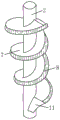
Fig. 1 is a schematic view of the overall structure of the present invention.
Fig. 2 is a schematic perspective view of the spindle.
Fig. 3 is a schematic view of a connecting structure of the scraping brush and the striker plate.
In the figure: 1. a dust collecting cylinder; 2. a main shaft; 3. a spiral channel; 4. an air inlet; 5. an air outlet; 6. a discharge outlet; 7. a helical blade; 8. a striker plate; 9. a support frame; 10. a vibration motor; 11. a discharge plate; 12. a motor; 13. scraping and brushing; 14. an air-tight device.
Detailed Description
The present invention will be described in further detail with reference to the accompanying drawings and specific embodiments.
The spiral dust collecting device shown in fig. 1-3 comprises a device body, wherein the device body comprises a dust collecting cylinder 1, and the dust collecting cylinder 1 is a cone; the dust collecting barrel 1 is made of a metal filter plate or a plastic filter plate or a filter cotton filter plate. Different manufacturing materials are selected according to the factors of the humidity, the temperature, the impurity content, the characteristics of impurities and the like of the dust.
The upper part of the dust collecting cylinder 1 is provided with an air inlet 4, and the lower part is provided with an air outlet 5; except for the air inlet 4, the air outlet 5 and the air closer 14, the dust collecting cylinder 1 is a sealing structure. The gas outlet 5 is connected with the exhaust pipe, a fan is arranged on the gas outlet 5 of the exhaust pipe extending out of the dust collection cylinder 1, the fan on the gas outlet 5 plays a role in air suction, and the fan increases the flowing power of gas.
The top end of the dust collecting barrel 1 is provided with a motor 12; the transmission shaft of the motor 12 extends into the dust collecting cylinder 1 through the bearing at the upper end of the main shaft 2 and is connected with the main shaft 2. The motor 12 is started, the transmission shaft rotates to drive the main shaft 2 to rotate, the main shaft 2 rotates to drive the spiral channel 3 to rotate, and dust falling into the spiral channel 3 enters the discharge port 6 along the spiral blades 7 to be discharged.
The middle part of the dust collecting barrel 1 is vertically provided with a main shaft 2; a spiral channel 3 is correspondingly arranged outside the main shaft 2; the dust falls into the spiral channel 3, and slides down to the discharge port 6 along the spiral blade 7 under the vibration of the vibration motor 10, so that the dust is prevented from being deposited on the inner wall of the dust collecting cylinder 1, and the dust is collected more quickly. The bottom of the spiral channel 3 is connected with a discharge port 6; the bottom of the discharge opening 6 is provided with an air lock 14; the bottom end of the spiral channel 3 is provided with a discharge plate 11; the discharge plate 11 is located at the top end of the discharge opening 6. The discharging plate 11 plays a role in connection, so that the accumulated dust can enter the discharging opening 6 more quickly.
The air lock 14 is fixedly connected with the discharge opening 6; the discharge opening 6 is arranged at the bottom end of the dust collecting cylinder 1 and extends into the support frame 9. The air seal device 14 plays a role in sealing and air-tight during dust and impurity discharging, and ensures that dust is smoothly discharged from the discharge port 6. The air seal device 14 prevents fine dust from being discharged from the air outlet, so that the dust removal effect is better and the dust removal efficiency is higher.
The spiral channel 3 comprises a spiral blade 7 which is spirally connected to the outer side of the main shaft 2; the side surface of the periphery of the helical blade 7 far away from the main shaft 2 is upwards provided with a material baffle plate 8; a plurality of scraping brushes 13 are arranged on the outer wall of the material baffle plate 8 at intervals; the scraping brushes are distributed at equal intervals; the scraping brushes 13 are all attached to the inner wall of the dust collecting cylinder 1;
the dust collecting cylinder 1 is provided with convex air holes. The air vent of the convex air vent is protruded on the dust collecting cylinder 1 and the height is uneven. The air vent with uneven height reduces the adhesion area of dust and weakens the adhesion force of the dust. The dust collecting cylinder 1 forms a convex air hole under the stamping action of a die, and an air hole on the convex air hole can be processed and manufactured by laser. The mouth of the ventilation hole made by laser processing is smooth, the smooth ventilation hole reduces the adhesion force of impurities on the ventilation hole, and the impurities are not easy to adhere to the ventilation hole of the convex ventilation hole and fall off easily. The distance between adjacent convex air holes is 2-10 mm; the aperture of the air vent of the convex air vent is 0.01-0.4 mm. The dust adhered on the vent hole of the convex vent hole is separated from the dust collecting cylinder 1 under the action of the scraping brush 13 of the rotating helical blade 7.
During operation, the dust and impurities on the dust collecting cylinder 1 are cleaned by the scraping brush 13 on the rotating spiral blade 7, and the dust and impurities cleaned by the scraping brush 13 are discharged through the discharge opening 6. The scraping brush 13 ensures the smoothness of the ventilation port of the convex ventilation hole on the dust collecting cylinder 1 and enhances the dust removing effect. The motor 12 is started, the motor 12 drives the main shaft 2 on the transmission shaft to rotate, the main shaft 2 rotates to drive the helical blade 7 to rotate, the scraping brush 13 on the helical blade 7 continuously cleans dust impurities on the dust collecting cylinder 1, and the dust impurities are discharged through the discharge opening 6. This design can be continuously incessantly collected dust impurity, and it is effectual not only to arrange dirt, and the dust is difficult to pile up, washs convenience moreover, labour saving and time saving.
The middle part of the dust collecting barrel 1 is provided with a supporting frame 9; the supporting frame 9 plays a role in supporting and stabilizing. The lower part of the dust collecting cylinder 1 is provided with a vibration motor 10; the number of the vibration motors 10 is two, and the two vibration motors are symmetrically arranged on the left side wall and the right side wall of the dust collecting barrel 1. The vibration motor 10 makes it easier for dust to collect in the spiral channel 3 and to quickly follow the spiral blade 7 into the discharge opening 6. The vibration motor 10 is located below the top surface of the support frame 9. The supporting frame 9 is a hollow structure; the middle part of the top surface of the supporting frame 9 is provided with a circular ring, and the middle part of the dust collecting barrel 1 is embedded in the circular ring of the supporting frame 9 in a matching way.
The utility model discloses a set up helical coiled passage, not only avoided tiny dust to discharge from the air outlet, improved dust collection efficiency, dust removal effect is good, has reduced the adhesion of dust moreover, scrapes the brush through the setting for the dust is difficult to pile up in the device, and the dust exhaust is effectual, and the inside washing of dust collection section of thick bamboo is simple simultaneously, and it is laborsaving to save trouble. In addition, the dust collector has simple structure and convenient use, and can be widely applied to various workplaces needing dust collectors.
The above embodiments are not intended to limit the present invention, and the present invention is not limited to the above examples, and the technical personnel in the technical field are in the present invention, which can also belong to the protection scope of the present invention.
Claims (6)
1. A spiral dust collecting device is characterized in that: the dust collector comprises a device body, wherein the device body comprises a dust collecting cylinder (1), and the dust collecting cylinder (1) is a cone; the upper part of the dust collecting cylinder (1) is provided with an air inlet (4), and the lower part is provided with an air outlet (5); the top end of the dust collecting cylinder (1) is provided with a motor (12); a main shaft (2) is vertically arranged in the middle of the dust collecting cylinder (1); a spiral channel (3) is correspondingly arranged outside the main shaft (2); the bottom of the spiral channel (3) is connected with a discharge port (6); an air-lock valve (14) is arranged at the bottom of the discharge opening (6);
the spiral channel (3) comprises a spiral blade (7) which is spirally connected to the outer side of the main shaft (2); the side surface of the periphery of the helical blade (7) far away from the main shaft (2) is upwards provided with a material baffle plate (8); a plurality of scraping brushes (13) are arranged on the outer wall of the striker plate (8) at intervals; the scraping brushes are distributed at equal intervals; the scraping brushes (13) are all attached to the inner wall of the dust collecting cylinder (1);
a support frame (9) is arranged in the middle of the dust collecting barrel (1); a vibration motor (10) is arranged at the lower part of the dust collecting cylinder (1); the number of the vibration motors (10) is two, and the two vibration motors are symmetrically arranged on the left side wall and the right side wall of the dust collection cylinder (1).
2. The spiral dust collector of claim 1, wherein: the support frame (9) is of a hollow structure; the middle part of the top surface of the supporting frame (9) is provided with a circular ring, and the middle part of the dust collecting barrel (1) is embedded in the circular ring of the supporting frame (9) in a matching way.
3. The spiral dust collector of claim 2, wherein: the air seal device (14) is fixedly connected with the discharge port (6); the discharge port (6) is arranged at the bottom end of the dust collecting cylinder (1) and extends into the support frame (9).
4. A spiral dust collector apparatus according to claim 3, wherein: a discharge plate (11) is arranged at the bottom end of the spiral channel (3); the discharge plate (11) is positioned at the top end of the discharge opening (6).
5. The spiral dust collector of claim 4, wherein: the transmission shaft of the motor (12) extends into the dust collecting cylinder (1) through a bearing at the upper end of the main shaft (2) and is connected with the main shaft (2).
6. A spiral dust collecting apparatus according to any one of claims 1 to 5, wherein: the vibration motor (10) is positioned below the top surface of the support frame (9).
Priority Applications (1)
| Application Number | Priority Date | Filing Date | Title |
|---|---|---|---|
| CN202020222597.5U CN212069182U (en) | 2020-02-26 | 2020-02-26 | Spiral dust collecting device |
Applications Claiming Priority (1)
| Application Number | Priority Date | Filing Date | Title |
|---|---|---|---|
| CN202020222597.5U CN212069182U (en) | 2020-02-26 | 2020-02-26 | Spiral dust collecting device |
Publications (1)
| Publication Number | Publication Date |
|---|---|
| CN212069182U true CN212069182U (en) | 2020-12-04 |
Family
ID=73559565
Family Applications (1)
| Application Number | Title | Priority Date | Filing Date |
|---|---|---|---|
| CN202020222597.5U Active CN212069182U (en) | 2020-02-26 | 2020-02-26 | Spiral dust collecting device |
Country Status (1)
| Country | Link |
|---|---|
| CN (1) | CN212069182U (en) |
-
2020
- 2020-02-26 CN CN202020222597.5U patent/CN212069182U/en active Active
Similar Documents
| Publication | Publication Date | Title |
|---|---|---|
| CN102125407A (en) | Dust collection barrel of dust collector with automatically cleaned filter | |
| CN214600580U (en) | Dust extraction is used in electronic product processing | |
| CN212069182U (en) | Spiral dust collecting device | |
| CN214019744U (en) | Bag-type dust collector with self-cleaning function | |
| CN210171039U (en) | Bag-type dust collector with self-cleaning dust exhaust mechanism | |
| CN211570873U (en) | Carding machine cleaning device | |
| CN110384989A (en) | The dust-extraction unit of low temperature moisture | |
| CN211963412U (en) | Bag type dust collector | |
| CN208852618U (en) | A kind of uprush combined duster | |
| CN110200547B (en) | Dust removal structure with metal mesh filtering structure | |
| CN111701974A (en) | Interior decoration dust isolation equipment | |
| CN218077106U (en) | Electric automatization automatic dust collector | |
| CN216262400U (en) | Ultrasonic cleaning machine for steel wire processing | |
| CN214598020U (en) | Waste gas conveying pipeline with cleaning mechanism | |
| CN214681888U (en) | Rice polishing preprocessing device | |
| CN210596753U (en) | Spiral rotary dust removal device | |
| CN211772292U (en) | Weaving workshop dust collector | |
| CN212140326U (en) | Novel dust remover | |
| CN209941167U (en) | High-efficient row material formula opener | |
| CN208212777U (en) | The dust-extraction unit of low temperature moisture | |
| CN219879409U (en) | Dust treatment mechanism convenient to clean | |
| CN218610766U (en) | Dust collecting device is used in circuit board production and processing | |
| CN220844625U (en) | Novel micro-power dust removal equipment for belt conveying | |
| CN219647005U (en) | High-efficiency gas dust remover | |
| CN210098327U (en) | Reduction furnace chassis electrode cleaning device |
Legal Events
| Date | Code | Title | Description |
|---|---|---|---|
| GR01 | Patent grant | ||
| GR01 | Patent grant |