CN218077106U - Electric automatization automatic dust collector - Google Patents
Electric automatization automatic dust collector Download PDFInfo
- Publication number
- CN218077106U CN218077106U CN202221860107.XU CN202221860107U CN218077106U CN 218077106 U CN218077106 U CN 218077106U CN 202221860107 U CN202221860107 U CN 202221860107U CN 218077106 U CN218077106 U CN 218077106U
- Authority
- CN
- China
- Prior art keywords
- dust
- removal cavity
- dust removal
- automatic
- dust collector
- Prior art date
- Legal status (The legal status is an assumption and is not a legal conclusion. Google has not performed a legal analysis and makes no representation as to the accuracy of the status listed.)
- Active
Links
Images


Abstract
The utility model discloses an electric automatization automatic dust collector, including the mounting bracket, install the dust removal cavity on the mounting bracket, be provided with the intake pipe on the lateral wall of dust removal cavity, the top of dust removal cavity is provided with the outlet duct, and the outlet duct extends to the inside and the mouth of pipe of dust removal cavity and is less than the intake pipe, and the bottom activity of dust removal cavity is provided with the dust collection bin who communicates with it. The utility model discloses an electric automatization automatic dust collector that provides, when removing dust, send dirty gas to the dust removal cavity through the intake pipe earlier, dirty gas and dust removal cavity's inner wall contact, and inner wall downstream along dust removal cavity, fall into the dust collection bin gradually, and cleaner gas is discharged from the outlet duct, because the outlet duct extends to the inside of dust removal cavity and the mouth of pipe is less than the intake pipe, dirty gas that gets into from the intake pipe can not discharge from the outlet duct at once, but can flow a period in dust removal cavity, guarantee from the outlet duct combustion gas all through cleaner.
Description
Technical Field
The utility model relates to a dust collecting equipment technical field relates to an automatic dust collector of electric automatization particularly.
Background
Dust can be generated in the process of producing a plurality of electric appliances automatically or the dust on the bottom surface can be raised, the health of workers is harmed, and the operation of equipment is influenced.
According to patent No. CN113070315B, published (public) No. 2022.04.01, an industrial electric automation dust removing device is disclosed, comprising: the vacuum cleaner comprises a dust hood and an air suction pipe, wherein the dust hood is arranged in the vertical direction, a dust suction opening is formed in the bottom end of the dust hood, the air suction pipe is arranged at the top end of the dust hood, one end of the air suction pipe is communicated with the dust hood, and the other end of the air suction pipe is communicated with a negative pressure adsorption device. The device includes suction hood, breathing pipe, the vertical direction setting of suction hood, the suction hood bottom is provided with the dust absorption mouth, the suction hood top is provided with the breathing pipe, breathing pipe one end with the suction hood intercommunication, the breathing pipe other end and negative pressure adsorption equipment intercommunication place the suction hood in electrical equipment's inside, produce the negative pressure through negative pressure adsorption equipment, with the inside dust of equipment through the breathing pipe discharge, compare in artifical brush cleaner, improved the efficiency of dust removal, dust removal effect is good.
In the prior art including above-mentioned patent, current electric automatization dust collector directly uses the air-blower to suck dirty gas mostly to set up the filter core at the air intake and the air outlet of air-blower, collect the dust in the factory building by the filter core, but this kind of dust collector needs frequent cleaning, change the filter core, and material cost and cost of labor are all than higher.
SUMMERY OF THE UTILITY MODEL
The utility model aims at providing an electric automatization automatic dust collector aims at solving traditional electric automatization dust collector and needs frequent clean, renew cartridge, consumes the great problem of manpower and materials.
In order to realize the above purpose, the utility model provides an electric automatization automatic dust collector, which comprises a mounting bracket, install the dust removal cavity on the mounting bracket, be provided with the intake pipe on the lateral wall of dust removal cavity, the top of dust removal cavity is provided with the outlet duct, the inside and the mouth of pipe that the outlet duct extends to the dust removal cavity are less than the intake pipe, the bottom activity of dust removal cavity is provided with the dust collection bin who communicates with it.
Preferably, the dust removing cavity comprises a cylindrical part and a conical cylindrical part, and the air inlet pipe is fixedly arranged on the cylindrical part, and the axis of the air inlet pipe is tangent to the inner wall of the cylindrical part.
Preferably, the bottom of the cone cylinder part is provided with a dust exhaust hole.
Preferably, a baffle plate for closing the dust exhaust hole is movably arranged on the cone cylinder part.
Preferably, the top of the dust collecting bin is movably provided with an insertion cylinder for inserting the dust exhaust hole.
Preferably, the dust collecting chamber is provided with a guide rod extending to the inside of the insertion tube.
Preferably, the guide rod is sleeved with a spring.
Preferably, a blower communicated with the air inlet pipe is arranged on the mounting frame.
Preferably, the side wall of the baffle is provided with an arc-shaped groove matched with the insertion cylinder.
Preferably, a filter element is arranged inside the air outlet pipe.
In the technical scheme, the utility model provides a pair of automatic dust collector of electric automation possesses following beneficial effect: when dust is removed, firstly, the dust-containing gas is sent to the dust removal cavity through the air inlet pipe, the dust-containing gas is contacted with the inner wall of the dust removal cavity, and moves downwards along the inner wall of the dust removal cavity, and gradually falls into the dust collection bin, and the cleaner gas is discharged from the air outlet pipe.
Drawings
In order to more clearly illustrate the embodiments of the present application or the technical solutions in the prior art, the drawings required to be used in the embodiments will be briefly described below, it is obvious that the drawings in the following description are only some embodiments described in the present invention, and other drawings can be obtained by those skilled in the art according to these drawings.
Fig. 1 is a schematic diagram of an overall structure provided by an embodiment of the present invention;
fig. 2 is a schematic view of an internal structure provided in an embodiment of the present invention;
FIG. 3 is an enlarged view taken at A in FIG. 2;
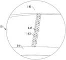
fig. 4 is an enlarged view of fig. 3 at B.
Description of reference numerals:
1. a mounting frame; 11. a dust removal cavity; 111. a cylindrical portion; 112. a cone part; 113. a baffle plate; 12. an air inlet pipe; 13. an air outlet pipe; 131. a filter element; 14. a dust collection bin; 141. an insertion tube; 142. a spring; 143. a guide bar; 2. a blower.
Detailed Description
In order to make the technical solution of the present invention better understood by those skilled in the art, the present invention will be further described in detail with reference to the accompanying drawings.
As shown in fig. 1-4, an electric automatic dust removing device comprises an installation frame 1, a dust removing cavity 11 is installed on the installation frame 1, an air inlet pipe 12 is arranged on the side wall of the dust removing cavity 11, an air outlet pipe 13 is arranged at the top of the dust removing cavity 11, the air outlet pipe 13 extends into the dust removing cavity 11, the pipe orifice of the air outlet pipe is lower than the air inlet pipe 12, and a dust collecting bin 14 communicated with the bottom of the dust removing cavity 11 is movably arranged at the bottom of the dust removing cavity 11.
In the above technical scheme, during dust removal, firstly, the dust-containing gas is sent to the dust-removing cavity 11 through the gas inlet pipe 12, the dust-containing gas is contacted with the inner wall of the dust-removing cavity 11, and moves downwards along the inner wall of the dust-removing cavity 11, and gradually falls into the dust-collecting chamber 14, and cleaner gas is discharged from the gas outlet pipe 13, because the gas outlet pipe 13 extends to the inside of the dust-removing cavity 11 and the pipe orifice is lower than the gas inlet pipe 12, the dust-containing gas entering from the gas inlet pipe 12 is not immediately discharged from the gas outlet pipe 13, but flows in the dust-removing cavity 11 for a period of time, it is ensured that the gas discharged from the gas outlet pipe 13 is cleaned, and the plot process does not need to be cleaned frequently, the filter element 131 is replaced, and dust is collected in the dust-collecting chamber 14, and can be recycled.
As a further embodiment of the present invention, as shown in fig. 2, the dust-removing chamber 11 includes a cylindrical portion 111 and a conical cylindrical portion 112, the air inlet pipe 12 is fixedly installed on the cylindrical portion 111, and the axis of the air inlet pipe is tangential to the inner wall of the cylindrical portion 111, the dust-containing gas entering the dust-removing chamber 11 from the air inlet pipe 12 flows along the inner wall of the cylindrical portion 111, and the dust in the gas slides downward along the inner wall of the cylindrical portion 111 and gradually moves into the dust-collecting bin 14 along the inner wall of the conical cylindrical portion 112.
As a further embodiment provided by the present invention, as shown in fig. 2-4, a dust exhaust hole is provided at the bottom of the cone cylinder part 112, a baffle 113 for closing the dust exhaust hole is movably provided on the cone cylinder part 112, an insertion cylinder 141 for inserting the dust exhaust hole is movably provided at the top of the dust collection bin 14, a guide rod 143 extending into the insertion cylinder 141 is provided on the dust collection bin 14, a spring 142 is sleeved on the guide rod 143, an arc-shaped groove adapted to the insertion cylinder 141 is provided on the sidewall of the baffle 113, when the dust collection bin 14 is replaced, the baffle 113 and the insertion cylinder 141 are tightly combined to prevent dust leakage in the dust collection cavity 11; when the dust collecting bin 14 is replaced, the inserting cylinder 141 is moved downwards along the guide rod 143 and the spring 142 is compressed, the inserting cylinder 141 leaves the cone cylinder part 112, at this time, the baffle 113 is tightly combined with the inserting cylinder 141 to seal the dust exhaust hole at the bottom of the cone cylinder part 112, the dust collecting bin 14 and the baffle 113 are synchronously moved again to enable the dust collecting bin 14 to gradually leave the dust exhaust hole, the baffle 113 gradually seals the dust exhaust hole, a new dust collecting bin 14 is placed on the mounting frame 1 and clings to the arc-shaped groove on the baffle 113, the dust collecting bin 14 and the baffle 113 are synchronously moved again to enable the baffle 113 to gradually leave the dust exhaust hole, the dust exhaust hole is gradually sealed by the dust collecting bin 14, and when the inserting cylinder 141 is just opposite to the dust exhaust hole, the inserting cylinder 141 is inserted into the dust exhaust hole under the action of the spring 142 to continue dust collecting work.
As a further embodiment provided by the present application, as shown in fig. 1, a blower 2 communicated with an air inlet pipe 12 is provided on the mounting frame 1, and the blower 2 can send the dust-containing gas into the air inlet pipe 12 and then into the dust-removing cavity 11.
Further, as shown in fig. 2, a filter element 131 is disposed inside the outlet pipe 13, and the filter element 131 can filter out fine dust in the gas flowing through the outlet pipe 13.
While certain exemplary embodiments of the present invention have been described above by way of illustration only, it will be apparent to those of ordinary skill in the art that the described embodiments may be modified in various different ways without departing from the spirit and scope of the present invention. Accordingly, the drawings and description are to be regarded as illustrative in nature and not as restrictive on the scope of the appended claims.
Claims (10)
1. The utility model provides an automatic dust collector of electric automatization, its characterized in that, includes mounting bracket (1), install dust removal cavity (11) on mounting bracket (1), be provided with intake pipe (12) on the lateral wall of dust removal cavity (11), the top of dust removal cavity (11) is provided with outlet duct (13), inside and the mouth of pipe that outlet duct (13) extend to dust removal cavity (11) are less than intake pipe (12), the bottom activity of dust removal cavity (11) is provided with dust collection bin (14) with it communicates.
2. The automatic electric automatic dust removing device according to claim 1, wherein the dust removing chamber (11) comprises a cylindrical part (111) and a conical cylindrical part (112), and the air inlet pipe (12) is fixedly arranged on the cylindrical part (111) and the axis of the air inlet pipe is tangential to the inner wall of the cylindrical part (111).
3. The automatic dust collector of claim 2, wherein the bottom of the cone part (112) is provided with a dust exhaust hole.
4. The automatic dust collector of claim 3, wherein a baffle (113) for closing the dust discharge hole is movably arranged on the cone part (112).
5. The automatic electric dust collector as claimed in claim 4, wherein the top of the dust collecting bin (14) is movably provided with an insertion tube (141) for inserting into the dust discharge hole.
6. The automatic dust removing device of claim 5, wherein the dust collecting chamber (14) is provided with a guide rod (143) extending to the inside of the insertion cylinder (141).
7. The automatic dust collector of claim 6, wherein the guide rod (143) is sleeved with a spring (142).
8. The automatic dust collector of claim 1, characterized in that the air blower (2) connected with the air inlet pipe (12) is arranged on the mounting rack (1).
9. The automatic dust collector of claim 5, wherein the side wall of the baffle (113) is provided with a circular arc-shaped groove adapted to the insertion cylinder (141).
10. The automatic dust collector of claim 1, wherein the air outlet pipe (13) is internally provided with a filter element (131).
Priority Applications (1)
| Application Number | Priority Date | Filing Date | Title |
|---|---|---|---|
| CN202221860107.XU CN218077106U (en) | 2022-07-19 | 2022-07-19 | Electric automatization automatic dust collector |
Applications Claiming Priority (1)
| Application Number | Priority Date | Filing Date | Title |
|---|---|---|---|
| CN202221860107.XU CN218077106U (en) | 2022-07-19 | 2022-07-19 | Electric automatization automatic dust collector |
Publications (1)
| Publication Number | Publication Date |
|---|---|
| CN218077106U true CN218077106U (en) | 2022-12-20 |
Family
ID=84482360
Family Applications (1)
| Application Number | Title | Priority Date | Filing Date |
|---|---|---|---|
| CN202221860107.XU Active CN218077106U (en) | 2022-07-19 | 2022-07-19 | Electric automatization automatic dust collector |
Country Status (1)
| Country | Link |
|---|---|
| CN (1) | CN218077106U (en) |
Cited By (1)
| Publication number | Priority date | Publication date | Assignee | Title |
|---|---|---|---|---|
| CN116272136A (en) * | 2023-05-18 | 2023-06-23 | 西安万珍农业科技有限公司 | Dust collection device for feed production |
-
2022
- 2022-07-19 CN CN202221860107.XU patent/CN218077106U/en active Active
Cited By (2)
| Publication number | Priority date | Publication date | Assignee | Title |
|---|---|---|---|---|
| CN116272136A (en) * | 2023-05-18 | 2023-06-23 | 西安万珍农业科技有限公司 | Dust collection device for feed production |
| CN116272136B (en) * | 2023-05-18 | 2023-08-11 | 西安万珍农业科技有限公司 | Dust collection device for feed production |
Similar Documents
| Publication | Publication Date | Title |
|---|---|---|
| CN218077106U (en) | Electric automatization automatic dust collector | |
| CN213492526U (en) | Industrial pulse dust collection processing device | |
| CN110200547B (en) | Dust removal structure with metal mesh filtering structure | |
| CN208442934U (en) | A kind of air purifier with self-cleaning function | |
| CN208032145U (en) | A kind of air purifier | |
| CN214809549U (en) | Multistage self-adjusting flue gas dust removal device | |
| CN213790490U (en) | High-voltage pulse dust remover convenient for internal dust removal | |
| CN214389344U (en) | Dust adsorption equipment in rubber processing | |
| CN2596927Y (en) | Water filtering type vacuum cleaner | |
| CN211133315U (en) | Pulse dust collector | |
| CN113739323A (en) | Household air purifier and air purification method | |
| CN219550761U (en) | Indoor air detection regulation and control device | |
| CN212941919U (en) | Boiler dust remover with self-cleaning filter element | |
| CN214715142U (en) | Air detection and purification equipment based on artificial intelligence | |
| CN215843580U (en) | Dust collecting device of air purifier | |
| CN217663913U (en) | Be used for dystopy thermal desorption ejection of compact dust keeper | |
| CN210711845U (en) | Pre-loosening cotton machine for producing oil absorption felt | |
| CN218249064U (en) | Cloth bag pulse dust collector convenient to clean | |
| CN215654370U (en) | Flue dust remover | |
| CN217829258U (en) | Dust remover for concrete production workshop | |
| CN217066237U (en) | Tool for cleaning gap part | |
| CN220071059U (en) | Welding fume high-voltage electrostatic purifying equipment | |
| CN216986786U (en) | Silicon-plastic plate dust remover capable of purifying water-containing smoke | |
| CN213221338U (en) | Stainless steel pulse bag-type dust collector | |
| CN218249189U (en) | A high efficiency dust collector for burning workshop |
Legal Events
| Date | Code | Title | Description |
|---|---|---|---|
| GR01 | Patent grant | ||
| GR01 | Patent grant |