CN211769996U - Movable gantry hanging bracket - Google Patents
Movable gantry hanging bracket Download PDFInfo
- Publication number
- CN211769996U CN211769996U CN201922229401.5U CN201922229401U CN211769996U CN 211769996 U CN211769996 U CN 211769996U CN 201922229401 U CN201922229401 U CN 201922229401U CN 211769996 U CN211769996 U CN 211769996U
- Authority
- CN
- China
- Prior art keywords
- hanging
- plate
- gantry crane
- mobile gantry
- cross beam
- Prior art date
- Legal status (The legal status is an assumption and is not a legal conclusion. Google has not performed a legal analysis and makes no representation as to the accuracy of the status listed.)
- Active
Links
Images

Landscapes
- Load-Engaging Elements For Cranes (AREA)
Abstract
The utility model provides a movable gantry hanging frame, which comprises two supporting frames, a crossbeam erected on the two supporting frames and a pulley arranged at the bottom of the supporting frame, wherein two ends of the crossbeam are respectively detachably connected with the top of the supporting frame; the mobile gantry hanging frame further comprises a hanging piece, and the hanging piece is provided with a sleeving part and a hanging rod for hanging the hoisting device; the sleeving part is sleeved at a preset stress position of the cross beam; the suspension rod is positioned below the preset stress position; the two ends of the suspension rod are respectively connected to the sleeving parts, so that the effect of improving the bearing capacity of the movable gantry hanger is achieved.
Description
Technical Field
The utility model belongs to the technical field of the jack-up, more specifically say, relate to a remove longmen gallows.
Background
The movable gantry hanger is generally used in occasions such as a mold manufacturing workshop, a machine tool manufacturing workshop, a steam repair factory, a building site and the like. In these cases, a large crane cannot be installed generally, and the working space is narrow. The movable gantry hanger has strong universality and is convenient to move in the occasions, so that a worker operates the movable gantry hanger to lift an object to be lifted and moves the object to a specified area, and the production efficiency is improved. The existing mobile gantry crane comprises two support frames. A cross beam is arranged between the two support frames, an electric hoist is suspended on the cross beam through a hanging ring, and universal wheels are arranged at the lower ends of the two support frames. According to stress analysis, when the electric hoist is hung in the middle of the cross beam, the bending moment borne by the cross beam is the largest, so that the weight capable of being hung by the movable gantry hanger is the largest. Because electric block directly hangs on rings, the area of contact between rings and the electric block is less, and when the weight of the heavy object of treating that removes gantry crane hoist and hoist was lifted was great, rings took place to warp easily.
SUMMERY OF THE UTILITY MODEL
An object of the utility model is to provide a remove gantry crane to solve the weight of waiting to play the heavy object that exists among the prior art when removing gantry crane and hoisting when great, rings take place the technical problem who warp easily.
In order to achieve the above object, the utility model adopts the following technical scheme: the movable gantry hanging bracket comprises two support frames, a cross beam arranged on the two support frames and a pulley arranged at the bottom of each support frame, wherein two ends of the cross beam are detachably connected with the tops of the support frames respectively;
the mobile gantry hanging frame further comprises a hanging piece, and the hanging piece is provided with a sleeving part and a hanging rod for hanging the hoisting device;
the sleeving part is sleeved at a preset stress position of the cross beam;
the suspension rod is positioned below the preset stress position;
the two ends of the suspension rod are respectively connected to the sleeving part.
Furthermore, the hanging part comprises a first plate, a second plate and limit blocks, the first plate is fixed at two ends of the hanging rod respectively, the second plate is fixed on the first plate at two ends of the hanging rod simultaneously, and the limit blocks are fixed on the first plate at two ends of the hanging rod respectively;
the sleeving part is formed among the first plate, the second plate and the limiting block.
Further, the suspension rod is a round rod.
The pulley is a universal wheel, the universal wheel comprises a rotating part, a roller and a locking part, the rotating part is connected to the support frame, the roller is rotatably connected to the rotating part, the locking part is arranged on the rotating part, and the universal wheel has a locking state and an unlocking state;
when the universal wheel is in the locking state, the locking part limits the rolling of the roller;
when the universal wheel is in the unlocked state, the locking part releases the limitation on the rolling of the roller.
Furthermore, the movable gantry crane also comprises a U-shaped part, the U-shaped part is fixed on the support frame, and the end part of the beam is detachably connected in a groove part of the U-shaped part.
Further, the movable gantry crane further comprises a high-strength screw, and the end part of the beam is connected in the groove part of the U-shaped part through the high-strength screw.
Further, the cross beam is a first square through pipe.
Further, the support frame includes three second side siphunculus and a plurality of third party siphunculus, and is three the second side siphunculus encloses and establishes to form the isosceles triangle frame, the both ends of third party siphunculus are fixed respectively isosceles triangle frame isometric on the second side siphunculus, it is a plurality of third party siphunculus equidistance sets up.
Furthermore, the movable gantry hanging frame further comprises a fourth through pipe, one end of the fourth through pipe is detachably connected to the third through pipe close to the cross beam, and one end, far away from the third through pipe, of the fourth through pipe is detachably connected to the cross beam.
Further, remove gantry crane frame still includes first reinforcing plate and second reinforcing plate, the both ends of fourth siphunculus are fixed with respectively first reinforcing plate, the second reinforcing plate is fixed on the crossbeam, one first reinforcing plate can dismantle the connection and be in on the third siphunculus, dorsad the third siphunculus first reinforcing plate can dismantle the connection and be in on the second reinforcing plate.
The utility model provides a pair of remove longmen gallows's beneficial effect lies in: compared with the prior art, the utility model discloses when changing the new hoisting apparatus of installation, owing to need not adjust hoisting apparatus position on the crossbeam, directly hang hoisting apparatus on hanging the pole, guarantee that the preset stress position of crossbeam carries out the atress when hoisting up and treating the jack-up thing of hoisting apparatus, improved the convenience of hoisting apparatus installation. The hanging piece is sleeved on the cross beam through the sleeving part, so that the hanging piece is directly installed at a preset stress position of the cross beam conveniently, and a heavy object to be lifted with larger weight can be hung by the movable gantry hanging frame. The hoisting device is hung on the hanging rod, and the transverse area of the hanging rod is larger than that of the hanging ring, so that the transverse contact area of the hanging part of the hoisting device and the hanging rod is large, when the object to be hoisted is hoisted by the movable gantry hanger, the stress of the contact part of the hoisting device and the hanging rod is more dispersed than that of the contact part of the hanging ring and the hoisting device, and the hanging rod is not easy to deform, so that the bearing capacity of the movable gantry hanger is improved. The two ends of the suspension rod are respectively connected to the sleeving parts, so that the force is transferred to the sleeving parts when the suspension rod is stressed, and the suspension rod is not easy to deform.
Drawings
In order to more clearly illustrate the technical solutions of the embodiments of the present invention, the drawings required for the embodiments or the prior art descriptions will be briefly introduced below, and it is obvious that the drawings in the following description are only some embodiments of the present invention, and it is obvious for those skilled in the art to obtain other drawings without inventive labor.
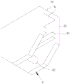
Fig. 1 is a schematic structural view of a mobile gantry crane provided in an embodiment of the present invention;
fig. 2 is a schematic structural diagram of a suspension member of a mobile gantry crane according to an embodiment of the present invention.
Wherein, in the figures, the respective reference numerals:
1. a support frame; 11. a second square through pipe; 12. a third-party pipe; 2. a cross beam; 3. a pulley; 4. a suspension member; 41. a housing portion; 42. a suspension rod; 43. a first plate; 44. a second plate; 45. a limiting block; 5. a U-shaped piece; 6. a fourth through pipe; 7. a hoisting device; 8. a first reinforcing plate; 9. a second reinforcing plate.
Detailed Description
In order to make the technical problem, technical solution and advantageous effects to be solved by the present invention more clearly understood, the following description is given in conjunction with the accompanying drawings and embodiments to illustrate the present invention in further detail. It should be understood that the specific embodiments described herein are merely illustrative of the invention and are not intended to limit the invention.
It will be understood that when an element is referred to as being "secured to" or "disposed on" another element, it can be directly on the other element or be indirectly on the other element. When an element is referred to as being "connected to" another element, it can be directly connected to the other element or be indirectly connected to the other element.
It will be understood that the terms "length," "width," "upper," "lower," "front," "rear," "left," "right," "vertical," "horizontal," "top," "bottom," "inner," "outer," and the like are used in an orientation or positional relationship indicated in the drawings for convenience in describing the invention and to simplify the description, and are not intended to indicate or imply that the device or element so referred to must have a particular orientation, be constructed and operated in a particular orientation, and thus should not be construed as limiting the invention.
Furthermore, the terms "first", "second" and "first" are used for descriptive purposes only and are not to be construed as indicating or implying relative importance or implicitly indicating the number of technical features indicated. Thus, a feature defined as "first" or "second" may explicitly or implicitly include one or more of that feature. In the description of the present invention, "a plurality" means two or more unless specifically limited otherwise.
Referring to fig. 1 and fig. 2, a mobile gantry crane according to the present invention will be described. A movable gantry hanging bracket comprises two support frames 1, a cross beam 2 erected on the two support frames 1 and pulleys 3 arranged at the bottoms of the support frames 1, wherein two ends of the cross beam 2 are detachably connected with the tops of the support frames 1 respectively;
the mobile gantry hanger further comprises a hanging piece 4, wherein the hanging piece 4 is provided with a sleeve part 41 and a hanging rod 42 for hanging the hoisting device 7;
the sleeving part 41 is sleeved at a preset stress position of the cross beam 2;
the suspension rod 42 is positioned below the preset stress position;
both ends of the suspension rod 42 are connected to the housing portions 41, respectively.
The utility model provides a pair of remove longmen gallows, compare with prior art, when changing the new hoisting apparatus 7 of installation, owing to need not adjust hoisting apparatus 7 position on crossbeam 2, directly hang hoisting apparatus 7 on hang pole 42, guarantee that hoisting apparatus 7 carries out the atress in the predetermined atress position of crossbeam 2 when hoisting and treating the jack-up thing, improved the convenience of hoisting apparatus 7 installation. The hanging piece 4 is sleeved on the cross beam 2 through the sleeving part 41, so that the hanging piece 4 is directly installed at a preset stress position of the cross beam 2, and a heavy object to be lifted with larger weight can be hung by the movable gantry hanging frame. The hoisting device 7 is hung on the hanging rod 42, and the transverse area of the hanging rod 42 is larger than that of the hanging ring, so that the transverse contact area between the hanging part 4 of the hoisting device 7 and the hanging rod 42 is large, when the gantry crane is moved to hoist a to-be-hoisted object, the stress at the contact part of the hoisting device 7 and the hanging rod 42 is more dispersed than that at the contact part of the hanging ring and the hoisting device 7, and the hanging rod 42 is not easy to deform, so that the bearing capacity of the movable gantry crane is improved. The two ends of the hanging rod 42 are respectively connected to the sleeving part 41, so that the hanging rod 42 can transmit force to the sleeving part 41 when stressed, and the hanging rod 42 is not easy to deform.
Specifically, the hoisting device 7 is provided as a hand hoist having a suspension structure or as an electric hoist having a suspension structure.
Optimally, the length of the cross beam 2 is set to be 1.8m, the height of the support frame 1 is set to be 2.4m, and the lifting device is very suitable for lifting a heavy object to be lifted during installation and debugging of equipment in a workshop, and is small in occupied space and convenient to operate.
Further, please refer to fig. 1 and fig. 2 together, as a specific embodiment of the present invention, the hanging member 4 includes a first plate 43, a second plate 44 and a limiting block 45, the two ends of the hanging rod 42 are respectively fixed with the first plate 43, the second plate 44 is simultaneously fixed on the first plates 43 at the two ends of the hanging rod 42, the limiting blocks 45 are respectively fixed on the first plates 43 at the two ends of the hanging rod 42;
the first plate 43, the second plate 44 and the stopper 45 form a sleeve portion 41 therebetween.
The hanging part 4 has simple structure and is very practical, which is beneficial to reducing the production cost of the movable gantry hanging bracket. The suspension rods 42 are fixed between the first plates 43, and the suspension rods 42 are not easy to deform under stress, so that the bearing weight of the movable gantry hanger is improved.
Specifically, the first plate 43 and the second plate 44 are provided as steel plates having a thickness of 20 mm.
Further, referring to fig. 1 and 2, as an embodiment of the present invention, the hanging rod 42 is a round rod.
The rod part of the round rod is smooth, so that the hanging part 4 of the hoisting device 7 can be hung on the round rod conveniently, and the hanging convenience of the hoisting device 7 is improved.
Specifically, phi of the round bar is 25 mm.
Further, referring to fig. 1 and fig. 2 together, as an embodiment of the present invention, a line connecting the center of the circular rod and the center of the cross beam 2 is perpendicular to the horizontal plane.
After the hoisting device 7 is hung on the round rod, when the hoisting device 7 hoists an object to be hoisted, the middle position of the cross beam 2 is stressed, and the bending moment borne by the cross beam 2 is the largest, so that the whole movable gantry hanging bracket can bear the largest load, the cross beam 2 is not easy to deform, and the risk that the movable gantry hanging bracket turns over is reduced.
Further, please refer to fig. 1 and fig. 2 together, as a specific embodiment of the present invention, the pulley 3 is a universal wheel, the universal wheel includes a rotating portion (not shown), a roller (not shown) and a locking portion (not shown), the rotating portion is connected to the supporting frame 1, the roller is rotatably connected to the rotating portion, the locking portion is disposed on the rotating portion, and the universal wheel has a locking state and an unlocking state;
when the universal wheel is in a locking state, the locking part limits the rolling of the roller;
when the universal wheel is in the unlocked state, the locking portion releases the restriction of the rolling of the roller.
In the process of hoisting the object to be hoisted to a proper height by the movable gantry crane, a worker stably supports the object to be hoisted and the movable gantry crane, and the universal wheels are in an unlocked state. Because this remove portal crane is at the in-process of lifting by crane the thing of waiting to jack-up, the thing of waiting to jack-up can take place to slope, leads to removing the focus of portal crane unstability, and the universal wheel can be in the action of gravity of the thing of waiting to jack-up and carry out corresponding removal automatically, and then makes the thing focus of waiting to jack-up on removing the portal crane tend towards steadily, and difficult emergence is rocked. When the movable gantry crane frame lifts the object to be lifted to a proper height, the worker directly pushes the support frame 1 to enable the movable gantry crane frame and the object to be lifted to move to the designated positions. When the object to be lifted on the movable gantry crane needs to be unloaded, the universal wheels are in a locked state by workers, the movable gantry crane is guaranteed not to move easily in the process of putting down the object to be lifted, and then the object to be lifted is stably put to an appointed position from the movable gantry crane. Compared with a movable gantry crane frame with an electric moving device, the movable gantry crane frame does not need to introduce wires, and the movable flexibility of the movable gantry crane frame is improved.
Specifically, four universal wheels are provided, and two universal wheels are fixed on each support frame 1.
Further, please refer to fig. 1 and fig. 2 together, as a specific embodiment of the present invention, the mobile gantry crane further includes a U-shaped member 5, the U-shaped member 5 is fixed on the supporting frame 1, the end of the beam 2 is detachably connected in the groove portion of the U-shaped member 5, the U-shaped member 5 makes the end of the beam 2 installed at the preset installation position of the supporting frame 1, so as to improve the convenience of installing the beam 2.
Further, please refer to fig. 1 and fig. 2 together, as the utility model provides a specific implementation of a remove gantry crane, remove gantry crane still includes high strength screw, and the tip of crossbeam 2 passes through high strength screw to be connected in the concave part of U-shaped spare 5, and high strength screw exerts great pretightning force for crossbeam 2 and connects on U-shaped spare 5 to make crossbeam 2 be difficult for breaking away from with U-shaped spare 5 when the atress takes place to bend, improved the bearing capacity who removes gantry crane.
Further, please refer to fig. 1 and fig. 2 together, as the utility model provides a specific implementation of a remove gantry crane, crossbeam 2 is established to the first party siphunculus, compares in the crossbeam 2 of I-steel, and the light in weight of first party siphunculus has better structural strength, when the gantry crane was removed in the equipment, the staff of being convenient for removed first party siphunculus, has improved and has removed gantry crane convenience.
Further, please refer to fig. 1 and fig. 2 together, as a specific embodiment of the present invention, the support frame 1 includes a third square tube 11 and a plurality of third square tubes 12, the three second square tube 11 encloses to form an isosceles triangle frame, the two ends of the third square tube 12 are fixed on the equal-length second square tube 11 of the isosceles triangle frame, the plurality of third square tubes 12 are arranged at equal intervals.
Support frame 1 comprises second square through pipe 11 and third square through pipe 12, compares in support frame 1 that solid piece constitutes, and the light in weight of second square through pipe 11 and third square through pipe 12 is convenient for the staff to remove support frame 1 when the portal crane is removed in the equipment, has improved and has removed portal crane convenience. The second square through pipe 11 and the third square through pipe 12 are light in weight, have good structural strength and are not easy to deform, and therefore the movable gantry crane can bear large weight.
Specifically, three third square through pipes 12 are welded to each isosceles triangular frame.
Further, please refer to fig. 1 and fig. 2 together, as a specific embodiment of the present invention, the mobile gantry crane further includes a fourth through pipe 6, one end of the fourth through pipe 6 is detachably connected to the third through pipe 12 close to the beam 2, and one end of the fourth through pipe 6 far away from the third through pipe 12 is detachably connected to the beam 2.
The fourth through pipe 6 plays a role of a reinforcing rib, so that the cross beam 2 is not easy to bend when stressed, and the bearing weight of the cross beam 2 is improved.
Further, please refer to fig. 1 and fig. 2 together, the mobile gantry crane further includes a first reinforcing plate 8 and a second reinforcing plate 9, the first reinforcing plate 8 is fixed at two ends of the fourth through pipe 6, the second reinforcing plate 9 is fixed on the cross beam 2, the first reinforcing plate 8 is detachably connected to the third through pipe 12, and the first reinforcing plate 8 facing away from the third through pipe 12 is detachably connected to the second reinforcing plate 9.
Through first reinforcing plate 8 and second reinforcing plate 9, make fourth siphunculus 6 stable connection between crossbeam 2 and third siphunculus 12, improve the bearing capacity who removes the portal jib gallows.
The above description is only exemplary of the present invention and should not be taken as limiting the scope of the present invention, as any modifications, equivalents, improvements and the like made within the spirit and principles of the present invention are intended to be included within the scope of the present invention.
Claims (10)
1. A movable gantry hanging bracket comprises two support frames, a cross beam arranged on the two support frames and pulleys arranged at the bottoms of the support frames, and is characterized in that two ends of the cross beam are detachably connected with the tops of the support frames respectively;
the mobile gantry hanging frame further comprises a hanging piece, and the hanging piece is provided with a sleeving part and a hanging rod for hanging the hoisting device;
the sleeving part is sleeved at a preset stress position of the cross beam;
the suspension rod is positioned below the preset stress position;
the two ends of the suspension rod are respectively connected to the sleeving part.
2. The mobile gantry crane of claim 1, wherein said hanger comprises a first plate, a second plate and a stop block, said first plate being fixed to both ends of said hanging rod, said second plate being fixed to said first plate at both ends of said hanging rod, said stop block being fixed to said first plate at both ends of said hanging rod;
the sleeving part is formed among the first plate, the second plate and the limiting block.
3. The mobile gantry crane of claim 2, wherein said hanger bar is provided as a round bar.
4. The mobile gantry crane of claim 1, wherein the pulley is configured as a universal wheel, the universal wheel comprising a rotating portion, a roller, and a locking portion, the rotating portion being connected to the support frame, the roller being rotatably connected to the rotating portion, the locking portion being provided on the rotating portion, the universal wheel having a locked state and an unlocked state;
when the universal wheel is in the locking state, the locking part limits the rolling of the roller;
when the universal wheel is in the unlocked state, the locking part releases the limitation on the rolling of the roller.
5. The mobile gantry crane of claim 1, further comprising a U-shaped member secured to the support frame, wherein an end of the beam is removably attached within a recessed portion of the U-shaped member.
6. The mobile gantry crane of claim 5, further comprising a high strength screw, wherein an end of the beam is connected within a recessed portion of the U-shaped member by the high strength screw.
7. The mobile gantry crane of claim 1, wherein the cross beam is provided as a first square tube.
8. The mobile gantry crane according to any one of claims 1 to 7, wherein the support frame comprises three second square tubes and a plurality of third square tubes, the three second square tubes form an isosceles triangular frame, two ends of the third square tubes are respectively fixed on the second square tubes with equal length of the isosceles triangular frame, and the plurality of third square tubes are arranged at equal intervals.
9. The mobile gantry crane of claim 8, further comprising a fourth through tube, wherein one end of the fourth through tube is detachably connected to the third through tube close to the beam, and one end of the fourth through tube far away from the third through tube is detachably connected to the beam.
10. A mobile gantry crane as claimed in claim 9, further comprising a first reinforcing plate and a second reinforcing plate, wherein the first reinforcing plate is fixed to each end of the fourth through pipe, the second reinforcing plate is fixed to the cross beam, the first reinforcing plate is detachably connected to the third through pipe, and the first reinforcing plate facing away from the third through pipe is detachably connected to the second reinforcing plate.
Priority Applications (1)
| Application Number | Priority Date | Filing Date | Title |
|---|---|---|---|
| CN201922229401.5U CN211769996U (en) | 2019-12-11 | 2019-12-11 | Movable gantry hanging bracket |
Applications Claiming Priority (1)
| Application Number | Priority Date | Filing Date | Title |
|---|---|---|---|
| CN201922229401.5U CN211769996U (en) | 2019-12-11 | 2019-12-11 | Movable gantry hanging bracket |
Publications (1)
| Publication Number | Publication Date |
|---|---|
| CN211769996U true CN211769996U (en) | 2020-10-27 |
Family
ID=72982054
Family Applications (1)
| Application Number | Title | Priority Date | Filing Date |
|---|---|---|---|
| CN201922229401.5U Active CN211769996U (en) | 2019-12-11 | 2019-12-11 | Movable gantry hanging bracket |
Country Status (1)
| Country | Link |
|---|---|
| CN (1) | CN211769996U (en) |
-
2019
- 2019-12-11 CN CN201922229401.5U patent/CN211769996U/en active Active
Similar Documents
| Publication | Publication Date | Title |
|---|---|---|
| CN113387267B (en) | Safe hoisting and lowering method for underground diaphragm wall reinforcement cage | |
| CN211769996U (en) | Movable gantry hanging bracket | |
| CN111056436A (en) | Gantry crane for mounting equipment | |
| CN212769426U (en) | Steel reinforcement cage hoisting accessory for hoist | |
| CN101850928A (en) | Special stability truss lifting tool for large-scale complete cross section | |
| CN110040618B (en) | Wall-hanging equipment fixing frock | |
| CN213976614U (en) | Special supplementary hoist device of construction | |
| CN211169550U (en) | Hoisting device for maintaining and replacing speed reducer | |
| CN211056518U (en) | Wheel hub hoist | |
| CN213085198U (en) | Balance hanging beam group lifting appliance | |
| CN211846848U (en) | Hoisting hanger device of steel reinforcement cage | |
| CN210658056U (en) | Bridge steel stand hoist and mount device of turning | |
| CN103508319B (en) | The bracing or strutting arrangement that uses and lift the method for one end of large-scale workpiece during upset large-scale workpiece | |
| CN210973627U (en) | Lifting tool for thrust cooler | |
| CN107612234B (en) | Core drawing and penetrating method for ultimate short shaft shoulder pole beam motor | |
| CN216426495U (en) | Hoist and mount compensating beam | |
| CN109264608B (en) | Trolley for hoisting tensioning jack for tensioning operation | |
| CN215593688U (en) | Bridge pipeline mounting platform | |
| CN213255263U (en) | Automobile wheel hub suspension type hangs empty spraying equipment | |
| CN217921042U (en) | Box girder steel formwork both arms hoist | |
| CN210796591U (en) | Special tooling hanger for air cooling coil pipe | |
| CN217201769U (en) | Special hoisting sling | |
| CN220245279U (en) | Lifting device for foil collecting cantilever of corrosion foil | |
| CN219826168U (en) | T roof beam template is demolishd and is used support | |
| CN212191204U (en) | Tool for hoisting die |
Legal Events
| Date | Code | Title | Description |
|---|---|---|---|
| GR01 | Patent grant | ||
| GR01 | Patent grant |