CN211711771U - A plate production line - Google Patents

A plate production line Download PDF

Info

Publication number
CN211711771U
CN211711771U CN202020141570.3U CN202020141570U CN211711771U CN 211711771 U CN211711771 U CN 211711771U CN 202020141570 U CN202020141570 U CN 202020141570U CN 211711771 U CN211711771 U CN 211711771U
Authority
CN
China
Prior art keywords
frame
clamping
plate
rotating
output end
Prior art date
Legal status (The legal status is an assumption and is not a legal conclusion. Google has not performed a legal analysis and makes no representation as to the accuracy of the status listed.)
Withdrawn - After Issue
Application number
CN202020141570.3U
Other languages
Chinese (zh)
Inventor
黄双成
李长城
Current Assignee (The listed assignees may be inaccurate. Google has not performed a legal analysis and makes no representation or warranty as to the accuracy of the list.)
Guangxi Tengsen Automation Equipment Co ltd
Original Assignee
Guangxi Tengsen Automation Equipment Co ltd
Priority date (The priority date is an assumption and is not a legal conclusion. Google has not performed a legal analysis and makes no representation as to the accuracy of the date listed.)
Filing date
Publication date
Application filed by Guangxi Tengsen Automation Equipment Co ltd filed Critical Guangxi Tengsen Automation Equipment Co ltd
Priority to CN202020141570.3U priority Critical patent/CN211711771U/en
Application granted granted Critical
Publication of CN211711771U publication Critical patent/CN211711771U/en
Withdrawn - After Issue legal-status Critical Current
Anticipated expiration legal-status Critical

Links

Images

Landscapes

  • Stacking Of Articles And Auxiliary Devices (AREA)

Abstract

本实用新型公开了一种板材生产线,包括叠板机、码垛机以及连接在叠板机和码垛机之间的转移机,叠板机包括夹送装置、接板装置和设置在夹送装置输出端的收板装置;接板装置位于夹送装置的输出端方向的两侧上均设置有可相向开合的接收导板,两组接收导板可相互配合调整板材沿输送方向的两侧位置并导向板材由下自上叠放在收板装置上;码垛机包括移动装置、转动装置和夹持装置,移动装置的输出端能够驱动转动装置实现空间位移,夹持装置可转动地安装在转动装置上,夹持装置包括驱动连杆组件以及至少一对可相向开合的夹托机构。本板材生产线能够将带有翘曲的板材逐张进行叠放成垛,并将这些板材堆垛进行稳固夹持码放。
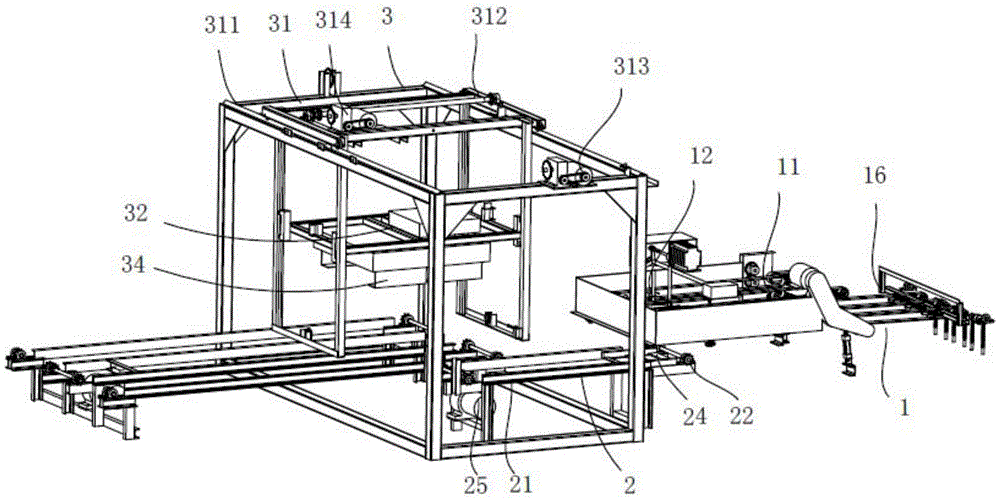
Figure 202020141570

The utility model discloses a plate production line, comprising a plate stacker, a stacker and a transfer machine connected between the plate stacker and the stacker. The plate receiving device at the output end of the device; the plate receiving device is located on both sides of the output end direction of the pinch device and is provided with receiving guide plates that can be opened and closed toward each other. The guide plates are stacked on the closing device from bottom to top; the palletizer includes a moving device, a rotating device and a clamping device. The output end of the moving device can drive the rotating device to realize spatial displacement, and the clamping device is rotatably installed on the rotating device. On the device, the clamping device includes a driving link assembly and at least a pair of clamping mechanisms that can be opened and closed toward each other. This board production line can stack the warped boards one by one into a stack, and hold the stacks of these boards firmly and stack them.

Figure 202020141570

Description

一种板材生产线A plate production line

技术领域technical field

本实用新型涉及板材生产领域,尤其涉及一种板材生产线。The utility model relates to the field of plate production, in particular to a plate production line.

背景技术Background technique

目前,在板材的初级加工过程中,基本都是将整根木头沿其圆周方向切削成均匀厚度的板片,然后通过初步压平、晾干或烘干、裁边等工序方可得到单张板材,这种板材由于是由整根木头切削得到,必然存在或多或少的翘曲问题。而在板材生产过程的最后一步,一般都需要将一定数量的单张板材堆叠成垛,然后利用人工或者外部搬运设备进行转移,然后按照一定的叠放方向进行码放。需要把板材进行堆放,方便运输。At present, in the primary processing of the board, the whole wood is basically cut into a board of uniform thickness along its circumference, and then the single sheet can be obtained through preliminary flattening, drying or drying, and trimming. Plate, since this kind of plate is obtained by cutting the whole wood, there must be more or less warping problems. In the last step of the board production process, it is generally necessary to stack a certain number of single boards into a stack, and then use manual or external handling equipment to transfer, and then stack them according to a certain stacking direction. Sheets need to be stacked for easy transportation.

但是目前的板材生产过程中,一般都是由工人将板材先进行堆垛,然后搬下加工生产线,既浪费人力,又浪费时间,并且工作效率低下,还会造成板材的损坏,产生不良品。而现有的板材生产线上几乎没有功能能够满足现有生产需求的堆垛设备,例如中国专利201920600444.7-一种用于地板堆垛的堆叠输送线,在该专利中只是简单地利用输送线将板材逐张叠放在堆叠装置内,并利用传送辊将成垛的板材向外输送;而上述专利中在传送辊将板材堆垛输送出来后,也没有配套有板材堆垛进行转移的设备,使得上述专利中的堆叠输送线也仅仅具有将逐张的板材堆放成垛的功能,并不具有在收集板材成垛的过程中规整板材堆垛的功能,同时也不具有将板材堆垛按照规定的堆叠方向将板材堆垛进行码放的功能,后续板材堆垛的码垛依然需要依靠人工或者外界的设备进行码放,十分麻烦。而采用人工进行码垛劳动强度大,容易损坏板材,如果采用外界的设备难以夹持稳固这些带有翘曲的板材堆垛,并且在转移过程中容易造成托板的情况出现。However, in the current plate production process, workers generally stack the plates first, and then move them off the processing production line, which is a waste of manpower and time, and the work efficiency is low, and it will also cause damage to the plates and produce defective products. However, there is almost no stacking equipment on the existing board production line that can meet the existing production needs, such as the Chinese patent 201920600444.7-a stacking conveyor line for floor stacking. In this patent, the board simply uses the conveyor line to Stack the sheets one by one in the stacking device, and use the conveying rollers to transport the stacks of sheets to the outside; and in the above-mentioned patent, after the conveying rollers transport the sheet stacks out, there is no equipment for transferring the sheet stacks, so that the above-mentioned The stacking conveyor line in the patent only has the function of stacking the sheets one by one into a stack, and does not have the function of orderly stacking the sheets in the process of collecting the sheets into a stack, and also does not have the function of stacking the sheets according to the regulations. The function of stacking the plates in the direction of the direction, the subsequent stacking of the plates still needs to rely on manual or external equipment for stacking, which is very troublesome. However, manual palletizing is labor-intensive, and it is easy to damage the plates. If external equipment is used, it is difficult to hold and stabilize the stacking of these warped plates, and it is easy to cause pallets during the transfer process.

实用新型内容Utility model content

本实用新型旨在至少解决上述所提及的技术问题之一,提供一种板材生产线,该板材生产线能够将带有翘曲的板材逐张进行叠放成垛,并将这些板材堆垛进行稳固夹持码放。The utility model aims to solve at least one of the above-mentioned technical problems, and provides a board production line, which can stack warped boards one by one into a stack, and stabilize the stacks of these boards. Clamp stacking.

为了实现上述目的,本实用新型采用的技术方案为:In order to achieve the above purpose, the technical scheme adopted by the present utility model is:

一种板材生产线,包括:A plate production line, comprising:

叠板机,包括夹送装置、接板装置和设置在夹送装置输出端的收板装置,所述夹送装置用于逐张夹送板材;所述接板装置位于夹送装置的输出端方向的两侧上均设置有可相向开合的接收导板,两组所述接收导板可相互配合调整板材沿输送方向的两侧位置并导向板材由下自上叠放在收板装置上;A plate stacking machine, comprising a pinch device, a plate pick-up device, and a board take-up device arranged at the output end of the pinch device, the pinch device is used for clipping the plates one by one; the board pick-up device is located in the direction of the output end of the pinch device Both sides of the machine are provided with receiving guide plates that can be opened and closed toward each other, and the two groups of receiving guide plates can cooperate with each other to adjust the position of the two sides of the board along the conveying direction, and guide the board to be stacked on the receiving device from bottom to top;

转移机,用于接收收板装置所输出的板材堆垛并向外输出板材堆垛;以及a transfer machine for receiving the stack of sheets output from the take-up device and outputting the stack of sheets to the outside; and

码垛机,包括移动装置、转动装置和夹持装置,所述移动装置的输出端能够驱动转动装置实现空间位移,所述夹持装置可转动地安装在转动装置上,所述夹持装置包括驱动连杆组件以及至少一对可相向开合的夹托机构,所述驱动连杆组件的输出端可驱动每对所述夹托机构开合夹持并托起转移机所输出的板材堆垛。A palletizer includes a moving device, a rotating device and a clamping device, the output end of the moving device can drive the rotating device to realize spatial displacement, the clamping device is rotatably mounted on the rotating device, and the clamping device includes A driving link assembly and at least a pair of clamping mechanisms that can be opened and closed toward each other, the output end of the driving link assembly can drive each pair of the clamping mechanisms to open and close to clamp and hold up the stack of plates output by the transfer machine .

作为上述技术方案的改进,所述夹持装置还包括可转动安装在转动装置输出端上的转动架,所述夹托机构铰接在转动架上,所述驱动连杆组件包括杠杆、推动杆和驱动机构,所述杠杆可转动地安装在转动架上,所述驱动机构的输出端与杠杆一端铰接,所述驱动机构可驱动杠杆自转;所述杠杆的两端均铰接至少一组所述推动杆的一端,所述推动杆的另一端与对应一侧的所述夹托机构的驱动端铰接,每组所述杠杆可通过与其所连接推动杆控制至少一对夹托机构开合夹持并托起板材堆垛。As an improvement of the above technical solution, the clamping device further includes a turret that is rotatably mounted on the output end of the rotating device, the clamping mechanism is hinged on the turret, and the drive link assembly includes a lever, a push rod and A drive mechanism, the lever is rotatably mounted on the turret, the output end of the drive mechanism is hinged with one end of the lever, and the drive mechanism can drive the lever to rotate; both ends of the lever are hinged at least one set of the pusher One end of the rod, the other end of the push rod is hinged with the driving end of the clamping mechanism on the corresponding side, and each group of the levers can control at least a pair of clamping mechanisms to open and close through the push rod connected to the lever to clamp and clamp. Hold up the stack of sheets.

作为上述技术方案的改进,所述夹托机构包括安装座、旋转轴、L型托板以及设置在旋转轴上的摆臂,所述安装座安装在转动架的一侧上,所述旋转轴可转动地安装在安装座上,所述L型托板安装在旋转轴上;所述摆臂向外的一端与推动杆的输出端铰接。As an improvement of the above technical solution, the clamping mechanism includes a mounting seat, a rotating shaft, an L-shaped support plate and a swing arm arranged on the rotating shaft, the mounting seat is mounted on one side of the turret, and the rotating shaft It is rotatably mounted on the mounting seat, and the L-shaped support plate is mounted on the rotating shaft; the outward end of the swing arm is hinged with the output end of the push rod.

作为上述技术方案的改进,所述转动装置包括底架、连杆机构和转动组件,所述底架安装在移动装置的输出端上,连杆机构和转动组件安装在底架上,所述转动架可转动地安装在底架上,所述转动组件的输出端与连杆机构的输入端偏心铰接,所述连杆机构的输出端与转动架的转动中心偏心铰接,所述转动组件可通过连杆机构带动转动架转动。As an improvement of the above technical solution, the rotating device includes a base frame, a link mechanism and a rotating assembly, the base frame is installed on the output end of the moving device, the connecting rod mechanism and the rotating assembly are installed on the base frame, and the rotating The frame is rotatably mounted on the bottom frame, the output end of the rotating assembly is eccentrically hinged with the input end of the link mechanism, the output end of the link mechanism is eccentrically hinged with the rotation center of the turret, and the rotating assembly can pass The link mechanism drives the turret to rotate.

作为上述技术方案的改进,所述连杆机构包括连接杆、摇臂和摆杆,所述摇臂的一端与连接杆一端铰接,所述摇臂的另一端与转动架的转动中心固接,所述连接杆的另一端与摆杆一端铰接,所述摆杆的另一端与转动组件的输出端固接。As an improvement of the above technical solution, the link mechanism includes a connecting rod, a rocker arm and a swing rod, one end of the rocker arm is hinged with one end of the connecting rod, and the other end of the rocker arm is fixedly connected to the rotation center of the turret, The other end of the connecting rod is hinged with one end of the swing rod, and the other end of the swing rod is fixedly connected with the output end of the rotating assembly.

作为上述技术方案的改进,所述移动装置包括第二机架和可滑动安装在第二机架上的移动架,所述第二机架上设置由于第一驱动组件,所述第一驱动组件可驱动移动架在第二机架上滑动;所述转动装置可升降地安装在移动架上,所述移动架上设置有用于升降转动装置的第二驱动组件。As an improvement of the above technical solution, the moving device includes a second frame and a moving frame slidably mounted on the second frame, and the second frame is provided with a first drive assembly, the first drive assembly The movable frame can be driven to slide on the second frame; the rotating device is movably mounted on the movable frame, and the movable frame is provided with a second drive assembly for lifting and lowering the rotating device.

作为上述技术方案的改进,所述叠板机还包括第一机架,所述夹送装置可转动地安装在第一机架上,所述第一机架位于夹送装置的输出端方向上设置有收垛区,所述收板装置沿夹送装置的输送方向可伸缩地设置在收垛区底部,并承接板材堆垛;两组所述接收导板沿夹送装置的输出端方向可相向开合的设置在收垛区的两侧,所述转移机的输入端可接收收垛区所输出的板材堆垛。As an improvement of the above technical solution, the stacking machine further includes a first frame, the pinch device is rotatably mounted on the first frame, and the first frame is located in the direction of the output end of the pinch device A stacking area is provided, and the plate receiving device is telescopically arranged at the bottom of the stacking area along the conveying direction of the pinch device, and accepts the stacking of plates; the two sets of receiving guide plates can face each other along the direction of the output end of the pinch device The opening and closing are arranged on both sides of the stacking area, and the input end of the transfer machine can receive the plate stacks output from the stacking area.

作为上述技术方案的改进,所述接板装置包括第一驱动电机、曲柄连杆组件以及可转动地安装在第一机架位于收垛区两侧上的摆轴,所述摆轴与夹送装置的输送方向平行;所述第一驱动电机的输出端与曲柄连杆组件的一端连接,所述曲柄连杆组件的另一端分别与收垛区两侧上的摆轴偏心连接,所述第一驱动电机可通过曲柄连杆组件驱动摆轴围绕自身轴心线摆动;所述接收导板安装摆轴上。As an improvement of the above technical solution, the plate connecting device includes a first drive motor, a crank connecting rod assembly, and a swing shaft rotatably installed on both sides of the stacking area of the first frame, the swing shaft and the pinch The conveying direction of the device is parallel; the output end of the first drive motor is connected with one end of the crank connecting rod assembly, the other end of the crank connecting rod assembly is eccentrically connected with the swing shafts on both sides of the stacking area, and the first A drive motor can drive the swing shaft to swing around its own axis through the crank connecting rod assembly; the receiving guide plate is mounted on the swing shaft.

作为上述技术方案的改进,所述夹送装置设置有底皮带和配合底皮带夹送板材的顶皮带,所述底皮带和顶皮带均可转动地安装在第一机架内;所述顶皮带长度长于底皮带的长度,并沿板材输送方向延伸跨越在收垛区的上方;所述收板装置沿夹送装置的输送方向可伸缩地设置在底皮带输出端的前下方;两组所述接收导板分别平行设置在底皮带输出端的两侧。As an improvement of the above technical solution, the pinch device is provided with a bottom belt and a top belt matching the bottom belt to pinch the plate, and both the bottom belt and the top belt can be rotatably installed in the first frame; the top belt The length is longer than that of the bottom belt, and extends above the stacking area along the conveying direction of the board; the plate-receiving device is telescopically arranged in front of and below the output end of the bottom belt along the conveying direction of the pinch device; the two sets of receiving The guide plates are respectively arranged on both sides of the output end of the bottom belt in parallel.

作为上述技术方案的改进,所述收板装置包括支撑叉和伸缩机构,所述支撑叉沿板材的输送方向可滑动地安装在第一机架上;所述伸缩机构的输出端可带动支撑叉伸入收垛区内以接收板材,或伸缩机构的输出端可带动支撑叉退出收垛区以将接收好的板材堆垛卸载在转移机的输入端上。As an improvement of the above technical solution, the plate closing device includes a support fork and a telescopic mechanism, the support fork is slidably installed on the first frame along the conveying direction of the plate; the output end of the telescopic mechanism can drive the support fork Extend into the stacking area to receive plates, or the output end of the telescopic mechanism can drive the support fork to exit the stacking area to unload the received plate stack on the input end of the transfer machine.

与现有技术相比本申请的有益效果是:Compared with the prior art, the beneficial effects of the present application are:

本实用新型的板材生产线利用接收导板导向夹送装置逐张输送过来的板材,使得板材能够整齐码垛在收板装置上,且接收导板可以调整开合角度能够适应不同规格的板材堆垛需求。此外利用移动装置作为驱动基础结构,能够带动转动装置实现空间位移动作,提高整个设备的灵活性,适合不同环境中的堆垛需求。此外设计有多对相向开合的夹托机构,利用驱动连杆组件驱动每对所述夹托机构相向摆动,以实现每对夹托机构开合夹持动作,实现了同步开合动作,避免了后期本夹托机构在夹持或者卸料时不容易出现钩板的现象,提高板材堆垛的质量;同时采用夹托机构夹持和托起板材堆垛两侧边沿的部分,可以有效地避免板材堆垛中存在翘曲板材时而夹持不稳固的现象,提高搬运的稳固性。本板材生产线设计巧妙,能够平整地叠放板材,而且可以有效地夹持带有翘曲的板材堆垛,灵活性强。The plate production line of the utility model utilizes the receiving guide plate to guide and pinch the plates conveyed one by one, so that the plates can be neatly stacked on the plate closing device, and the receiving guide plate can adjust the opening and closing angle to adapt to the stacking requirements of plates of different specifications. In addition, using the mobile device as the driving base structure can drive the rotating device to realize spatial displacement action, improve the flexibility of the entire equipment, and be suitable for stacking requirements in different environments. In addition, a plurality of pairs of clamping mechanisms that open and close in opposite directions are designed, and each pair of clamping mechanisms is driven to swing relative to each other by the driving link assembly, so as to realize the opening and closing of each pair of clamping mechanisms. In the later stage, the clamping mechanism is not prone to the phenomenon of hooking the plate when clamping or unloading, and the quality of the plate stacking is improved. It avoids the phenomenon that the warped plates are sometimes not firmly clamped in the stacking of plates, and improves the stability of handling. The board production line is ingeniously designed, can stack the boards flat, and can effectively clamp the warped board stacks, with strong flexibility.

附图说明Description of drawings

以下结合附图对本实用新型的具体实施方式作进一步的详细说明,其中:The specific embodiments of the present utility model will be described in further detail below in conjunction with the accompanying drawings, wherein:

图1为本实用新型实施例的结构示意图一;Fig. 1 is the structural representation one of the embodiment of the present utility model;

图2为本实用新型实施例的结构示意图二;Fig. 2 is the structural representation two of the embodiment of the present utility model;

图3为本实用新型实施例中叠板机的结构示意图一;Fig. 3 is the structural schematic diagram 1 of the board stacker in the embodiment of the present utility model;

图4为本实用新型实施例中叠板机的结构示意图二;Fig. 4 is the second structural schematic diagram of the plate stacker in the embodiment of the utility model;

图5为本实用新型实施例中叠板机的部分结构示意图;Fig. 5 is the partial structure schematic diagram of the board stacker in the embodiment of the utility model;

图6为本实用新型实施例中转移机的结构示意图;Fig. 6 is the structural representation of the transfer machine in the embodiment of the utility model;

图7为本实用新型实施例中码垛机的结构示意图一;Fig. 7 is the structural schematic diagram 1 of the palletizer in the embodiment of the present utility model;

图8为本实用新型实施例中码垛机的结构示意图二;Fig. 8 is the second structural schematic diagram of the palletizer in the embodiment of the utility model;

图9为本实用新型实施例中码垛机的部分结构示意图;Fig. 9 is the partial structural schematic diagram of the palletizer in the embodiment of the utility model;

图10为本实用新型实施例中转动装置的结构示意图一;Fig. 10 is the first structural schematic diagram of the rotating device in the embodiment of the present invention;

图11为本实用新型实施例中转动装置的结构示意图二;11 is a second structural schematic diagram of a rotating device in an embodiment of the present invention;

图12为本实用新型实施例中驱动连杆组件与夹托机构配合的结构示意图一;12 is a first structural schematic diagram of the cooperation between the driving link assembly and the clamping mechanism in the embodiment of the present invention;

图13为本实用新型实施例中驱动连杆组件与夹托机构配合的结构示意图二。13 is a second structural schematic diagram of the cooperation between the driving link assembly and the clamping mechanism in the embodiment of the present invention.

具体实施方式Detailed ways

下面将结合本实用新型实施例中的附图,对本实用新型实施例中的技术方案进行清楚、完整地描述,显然,所描述的实施例仅仅是本实用新型的一部分实施例,而不是全部的实施例。基于本实用新型中的实施例,本领域普通技术人员在没有做出创造性劳动前提下所获得的所有其他实施例,都属于本实用新型保护的范围。The technical solutions in the embodiments of the present utility model will be clearly and completely described below with reference to the accompanying drawings in the embodiments of the present utility model. Obviously, the described embodiments are only a part of the embodiments of the present utility model, not all of them. Example. Based on the embodiments of the present invention, all other embodiments obtained by those of ordinary skill in the art without creative work fall within the protection scope of the present invention.

需要说明的是,当组件被称为“固定于”另一个组件,它可以直接在另一个组件上或者也可以存在居中的组件。当一个组件被认为是“连接”另一个组件,它可以是直接连接到另一个组件或者可能同时存在居中组件。当一个组件被认为是“设置于”另一个组件,它可以是直接设置在另一个组件上或者可能同时存在居中组件,当部件被称为“设置在中部”,不仅仅是设置在正中间位置,只要不是设置在两端部都属于中部所限定的范围内。本文所使用的术语“垂直的”、“水平的”、“左”、“右”以及类似的表述只是为了说明的目的。It should be noted that when a component is referred to as being "fixed to" another component, it can be directly on the other component or there may also be a centered component. When a component is considered to be "connected" to another component, it may be directly connected to the other component or there may be a co-existence of an intervening component. When a component is said to be "set on" another component, it can be set directly on the other component or there may be a centered component at the same time, when a component is said to be "set in the middle", not just in the middle , as long as it is not set in the range limited by the middle part at both ends. The terms "vertical," "horizontal," "left," "right," and similar expressions are used herein for illustrative purposes only.

除非另有定义,本文所使用的所有的技术和科学术语与属于本实用新型的技术领域的技术人员通常理解的含义相同。本文中在本实用新型的说明书中所使用的术语只是为了描述具体的实施例的目的,不是旨在于限制本实用新型。本文所使用的术语“及/或”包括一个或多个相关的所列项目的任意的和所有的组合Unless otherwise defined, all technical and scientific terms used herein have the same meaning as commonly understood by one of ordinary skill in the technical field to which the present invention belongs. The terms used in the description of the present invention herein are only for the purpose of describing specific embodiments, and are not intended to limit the present invention. As used herein, the term "and/or" includes any and all combinations of one or more of the associated listed items

如图1至图13所示,本实用新型提供了一种板材生产线,包括叠板机1、转移机2和码垛机3,其中,叠板机1包括夹送装置11、接板装置12和设置在夹送装置11输出端的收板装置13,所述夹送装置11用于逐张夹送板材;所述接板装置12位于夹送装置11的输出端方向的两侧上均设置有可相向开合的接收导板121,两组所述接收导板121可相互配合调整板材沿输送方向的两侧位置并导向板材由下自上叠放在收板装置13上。而转移机2用于接收收板装置13所输出的板材堆垛并向外输出板材堆垛;码垛机3包括移动装置31、转动装置32和夹持装置,所述移动装置31的输出端能够驱动转动装置32实现空间位移,所述夹持装置可转动地安装在转动装置32上,所述夹持装置包括驱动连杆组件33以及至少一对可相向开合的夹托机构34,所述驱动连杆组件33的输出端可驱动每对所述夹托机构34开合夹持并托起转移机2所输出的板材堆垛。需要说明的是,在本申请中所堆垛以及搬运的板材主要为还未压合成型的板片毛坯,因此基本存在翘曲的现象,同时单张板片毛坯由于展开面积大,容易形变。为此在本申请中接收导板121的作用在一定程度能够限制夹送装置11所输出板材的两侧,防止板材跳动,当板材完全送出夹送装置11后,板材的两侧边沿两组所述接收导板121所限制,由于失去了出夹送装置11的支撑,因此板材会沿着两组所述接收导板121的导向方向向下掉落,进入到收板装置13内,实现逐张板材的秩序堆叠。为此本申请中采用至少一对夹托机构34相互配合进行夹持并托起板材堆垛的两侧边缘部分,在夹持的过程中可以有效地从夹托机构34的开合方向进行调整板材堆垛与夹托机构34接触面的平整性,实现调整并齐平板材堆垛的效果,而当每对夹托机构34夹持到位后,夹托机构34还能托起整个板材堆垛两侧的边缘部分,避免板材堆垛出现脱板或者夹持不稳的情况。要实现夹持和托起板材堆垛的效果,本申请中夹托机构34为常规的钩块结构,这样即可实现同时调整板材堆垛的两侧以及托起板材堆垛的两侧底部。关于夹托机构34的具体结构,下文有详细说明,本申请在此不详述。As shown in FIGS. 1 to 13 , the present invention provides a plate production line, including a plate stacker 1 , a transfer machine 2 and a stacker 3 , wherein the plate stacker 1 includes a pinch device 11 and a plate connecting device 12 And the plate receiving device 13 arranged at the output end of the pinch device 11, the pinch device 11 is used to pinch the plates one by one; The receiving guide plates 121 can be opened and closed toward each other. The two sets of receiving guide plates 121 can cooperate with each other to adjust the positions of the two sides of the board along the conveying direction and guide the board to be stacked on the board receiving device 13 from bottom to top. The transfer machine 2 is used to receive the stacks of sheets output by the stacking device 13 and output the stacks of sheets to the outside; the stacker 3 includes a moving device 31, a rotating device 32 and a clamping device. The output end of the moving device 31 The rotating device 32 can be driven to realize spatial displacement, and the clamping device is rotatably mounted on the rotating device 32, and the clamping device includes a driving link assembly 33 and at least a pair of clamping mechanisms 34 that can be opened and closed toward each other. The output end of the driving link assembly 33 can drive each pair of the clamping mechanisms 34 to open and close to clamp and support the stack of plates output by the transfer machine 2 . It should be noted that the sheets stacked and transported in this application are mainly sheet blanks that have not yet been pressed into shape, so there is basically a warpage phenomenon, and a single sheet blank is easily deformed due to its large expansion area. Therefore, in the present application, the function of the receiving guide plate 121 can limit the two sides of the board output by the pinch device 11 to a certain extent, and prevent the board from jumping. Restricted by the receiving guide plate 121, because the support of the output pinch device 11 is lost, the plate will fall down along the guiding direction of the two sets of receiving guide plates 121, and enter the plate receiving device 13 to realize the plate-by-plate operation. Stacked in order. For this reason, in the present application, at least a pair of clamping mechanisms 34 are used to clamp and hold up the edge portions on both sides of the sheet stack. During the clamping process, the opening and closing directions of the clamping mechanisms 34 can be effectively adjusted. The flatness of the contact surface between the plate stacking and the clamping mechanism 34 achieves the effect of adjusting and aligning the plate stacking, and when each pair of clamping mechanisms 34 is clamped in place, the clamping mechanism 34 can also hold up the entire plate stack. The edge parts on both sides can avoid the plate stacking from falling off or unstable clamping. To achieve the effect of clamping and holding up the board stack, the clamping mechanism 34 in the present application is a conventional hook block structure, so that the two sides of the board stack can be adjusted and the bottoms of both sides of the board stack can be simultaneously adjusted. The specific structure of the clamping mechanism 34 will be described in detail below, and will not be described in detail in this application.

参见图1至图5,所述叠板机1还包括第一机架14,所述夹送装置11可转动地安装在第一机架14上,所述第一机架14位于夹送装置11的输出端方向上设置有收垛区15,所述收板装置13沿夹送装置11的输送方向可伸缩地设置在收垛区15底部,并承接板材堆垛;两组所述接收导板121沿夹送装置11的输出端方向可相向开合的设置在收垛区15的两侧,所述转移机2的输入端可接收收垛区15所输出的板材堆垛。其中,在本申请中夹送装置11的输入端上还设置有输送机构16,其中输送机构16包括平面输送带161以及一个可以调节输送角度的调节输送带162,平面输送带161可转动地安装在第一机架14上,调节输送带162可转动安装在调节架163上,调节架163一端铰接在第一机架14上,调节架163输出的一端两侧设置有调节气缸164,用以调节调节输送带162的输出角度。在本申请中调节输送带162连接在夹送装置11之间,用于给夹送装置11喂送板材。需要说明的是,在本申请中收垛区15是由两组所述接收导板121、收板装置13、夹送装置11的输出端以及第一机架14限制得到,其中两组所述接收导板121置于收垛区15沿板材输送方向的两侧,第一机架14设置在收垛区15沿板材输送方向前端,同理收板装置13置于收垛区15的底部,用于支撑板材堆垛。Referring to FIG. 1 to FIG. 5 , the stacking machine 1 further includes a first frame 14 , and the pinch device 11 is rotatably mounted on the first frame 14 , and the first frame 14 is located in the pinch device A stacking area 15 is provided in the direction of the output end of the 11, and the plate receiving device 13 is telescopically arranged at the bottom of the stacking area 15 along the conveying direction of the pinch device 11, and accepts the stacking of plates; two sets of the receiving guide plates The 121 is provided on both sides of the stacking area 15 along the direction of the output end of the pinch device 11 , which can be opened and closed toward each other. Wherein, in the present application, the input end of the pinch device 11 is also provided with a conveying mechanism 16, wherein the conveying mechanism 16 includes a flat conveying belt 161 and an adjustment conveying belt 162 that can adjust the conveying angle, and the flat conveying belt 161 is rotatably installed On the first frame 14 , the adjusting conveyor belt 162 is rotatably mounted on the adjusting frame 163 , one end of the adjusting frame 163 is hinged on the first frame 14 , and two sides of the output end of the adjusting frame 163 are provided with adjusting cylinders 164 for The adjustment adjusts the output angle of the conveyor belt 162 . In the present application, the adjustment conveyor belt 162 is connected between the pinch devices 11 for feeding the pinch devices 11 with sheets. It should be noted that in the present application, the stacking area 15 is limited by two sets of the receiving guides 121 , the receiving device 13 , the output end of the pinch device 11 and the first frame 14 , wherein the two sets of the receiving guides The guide plates 121 are placed on both sides of the stacking area 15 along the sheet conveying direction. The first frame 14 is arranged at the front end of the stacking area 15 along the sheet conveying direction. Similarly, the stacking device 13 is placed at the bottom of the stacking area 15. Support the stacking of sheets.

进一步参见图3和图4,所述夹送装置11设置有底皮带111和配合底皮带111夹送板材的顶皮带112,所述底皮带111和顶皮带112均可转动地安装在第一机架14内;所述顶皮带112长度长于底皮带111的长度,并沿板材输送方向延伸跨越在收垛区15的上方;所述收板装置13沿夹送装置11的输送方向可伸缩地设置在底皮带111输出端的前下方;两组所述接收导板121分别平行设置在底皮带111输出端的两侧。其中底皮带111端连接与上述的调节输送带162的输出端,当然为了避免板材在输送带162输出后,而未进入到底皮带111之前的上翘,本申请的一个实施例中在调节输送带162的输出端与底皮带111之间的上方设置有一个随动皮带,用以防止调节输送带162所述输出的板材出现上翘的情况。在本申请中顶皮带112长度长于底皮带111的长度,其主要目的是为了避免板材在完全输出底皮带111之后向上飞起,同时保证板材平稳落入到两组所述接收导板121之间。板材从底皮带111与顶皮带112的夹送空间内输出后,会相向飞落,为此本申请中第一机架14位于夹送装置11的输送方向前端的位置上,设置有一压舌板17,压舌板17倾斜设置,其中压舌板17靠近夹送装置11的一端高于远离夹送装置11的另一端,这样的设计便于夹送装置11的板材被导向掉落在收垛区15内。Further referring to FIGS. 3 and 4 , the pinch device 11 is provided with a bottom belt 111 and a top belt 112 matched with the bottom belt 111 to pinch the plate, and both the bottom belt 111 and the top belt 112 are rotatably installed on the first machine The top belt 112 is longer than the bottom belt 111, and extends above the stacking area 15 along the conveying direction of the sheet; In front and below the output end of the bottom belt 111 ; two sets of the receiving guide plates 121 are respectively arranged on both sides of the output end of the bottom belt 111 in parallel. The end of the bottom belt 111 is connected to the output end of the above-mentioned adjusting conveyor belt 162. Of course, in order to avoid the upturn of the sheet after the conveyor belt 162 is output but before entering the bottom belt 111, in one embodiment of the present application, the adjusting conveyor belt is A follow-up belt is arranged above between the output end of the conveyor belt 162 and the bottom belt 111, so as to prevent the upward warping of the sheet for adjusting the output of the conveyor belt 162. In this application, the length of the top belt 112 is longer than that of the bottom belt 111 , and its main purpose is to prevent the board from flying upward after the bottom belt 111 is completely output, and to ensure that the board smoothly falls between the two sets of receiving guide plates 121 . After the plate is output from the pinch space between the bottom belt 111 and the top belt 112, it will fly down toward each other. Therefore, in the present application, the first frame 14 is located at the front end of the pinch device 11 in the conveying direction, and is provided with a tongue depressor. 17. The tongue depressor 17 is arranged obliquely, wherein one end of the tongue depressor 17 close to the pinch device 11 is higher than the other end away from the pinch device 11, such a design is convenient for the plates of the pinch device 11 to be guided to fall in the stacking area within 15.

在本申请的一个实施例中,收板装置13在接收了一定数量的板材后,由于大多板材存在翘曲,为了更好地使得收板装置13能够接收更多的板材,在收垛区15的顶部上设置有一个下压机构18,其中下压机构18可以采用气缸或直线电机带动一个压架实现。In an embodiment of the present application, after receiving a certain number of plates, the plate receiving device 13 is warped because most plates are warped. In order to better enable the plate receiving device 13 to receive more plates, the stacking area 15 There is a pressing mechanism 18 on the top of the fuselage, wherein the pressing mechanism 18 can be realized by using a cylinder or a linear motor to drive a pressing frame.

进一步参见图5,所述接板装置12包括第一驱动电机124、曲柄连杆组件122以及可转动地安装在第一机架14位于收垛区15两侧上的摆轴123,所述摆轴123与夹送装置11的输送方向平行;所述第一驱动电机124的输出端与曲柄连杆组件122的一端连接,所述曲柄连杆组件122的另一端分别与收垛区15两侧上的摆轴123偏心连接,所述第一驱动电机124可通过曲柄连杆组件122驱动摆轴123围绕自身轴心线摆动;所述接收导板121安装摆轴123上。其中两组接收导板121可围绕摆轴123的轴心线进行相向开合动作,以适应夹送装置11所输送过来不同位置的板材,达到调整板材的目的。需要说明的是,曲柄连杆组件122可以为常规的曲柄连杆结构即可,只要能实现摆轴123围绕自身轴心线摆动即可。但是在本申请的一个实施例中曲柄连杆组件122包括曲柄1221、第一连杆1222、摆动轴1223、提杆1224以及与摆轴123偏性连接的连动杆1225,其中摆动轴1223横向架设在第一机架14上,且位于夹送装置11的上方,摆动轴1223的两端上设置有V型连接块1226;此外曲柄1221安装在第一驱动电机124的输出端上,而第一连杆1222一端与曲柄1221偏心铰接,另一端与V型连接块1226的一端铰接,V型连接块1226的另一端与提杆1224一端铰接,所述提杆1224另一端与连动杆1225铰接。其中,而摆动轴1223的另一端还可以与另一组提杆1224偏心铰接,使得两侧的摆轴123一并能够实现联动。其工作原理是在上述第一驱动电机124转动后,首先带动曲柄1221转动,曲柄1221的偏心作用驱动第一连杆1222往复推动摆动轴1223围绕自身轴心线摆动,进而V型连接块1226驱动摆动轴1223摆动后,摆轴123分别带动通过提杆1224驱动摆轴123围绕自身轴心线摆动,最终达到调节两侧接收导板121开合的作用。Further referring to FIG. 5 , the plate connecting device 12 includes a first driving motor 124 , a crank connecting rod assembly 122 and a swing shaft 123 rotatably mounted on both sides of the stacking area 15 of the first frame 14 . The shaft 123 is parallel to the conveying direction of the pinch device 11 ; the output end of the first drive motor 124 is connected to one end of the crank connecting rod assembly 122 , and the other end of the crank connecting rod assembly 122 is respectively connected to both sides of the stacking area 15 The upper swing shaft 123 is eccentrically connected, and the first drive motor 124 can drive the swing shaft 123 to swing around its own axis through the crank connecting rod assembly 122 ; the receiving guide plate 121 is mounted on the swing shaft 123 . The two sets of receiving guide plates 121 can open and close relative to each other around the axis line of the swing shaft 123, so as to adapt to the plates conveyed by the pinch device 11 at different positions, so as to achieve the purpose of adjusting the plates. It should be noted that the crank connecting rod assembly 122 may be a conventional crank connecting rod structure, as long as the swing shaft 123 can swing around its own axis. However, in an embodiment of the present application, the crank connecting rod assembly 122 includes a crank 1221, a first connecting rod 1222, a swing shaft 1223, a lifting rod 1224, and a link rod 1225 eccentrically connected to the swing shaft 123, wherein the swing shaft 1223 is transverse It is erected on the first frame 14 and located above the pinch device 11. V-shaped connecting blocks 1226 are provided on both ends of the swing shaft 1223; One end of a connecting rod 1222 is eccentrically hinged with the crank 1221, and the other end is hinged with one end of the V-shaped connecting block 1226. The other end of the V-shaped connecting block 1226 is hinged with one end of the lifting rod 1224, and the other end of the lifting rod 1224 is hinged with the connecting rod 1225. Hinged. Wherein, the other end of the swing shaft 1223 can also be eccentrically hinged with another group of lifting rods 1224, so that the swing shafts 123 on both sides can be linked together. Its working principle is that after the first driving motor 124 rotates, it first drives the crank 1221 to rotate, and the eccentric action of the crank 1221 drives the first connecting rod 1222 to reciprocate and push the swing shaft 1223 to swing around its own axis line, and then the V-shaped connecting block 1226 drives After the swing shaft 1223 swings, the swing shaft 123 drives the swing shaft 123 to swing around its own axis through the lifting rod 1224 respectively, and finally achieves the function of adjusting the opening and closing of the receiving guide plates 121 on both sides.

参见图3至图5,在本申请中收板装置13主要是支撑收垛区15内的板材堆垛,同时可以简单地理解为收板装置13作为收垛区15与转移机2之间的开关。为此本申请中所述收板装置13包括支撑叉131和伸缩机构,所述支撑叉131沿板材的输送方向可滑动地安装在第一机架14上;所述伸缩机构的输出端可带动支撑叉131伸入收垛区15内以接收板材,或伸缩机构的输出端可带动支撑叉131退出收垛区15以将接收好的板材堆垛卸载在转移机2的输入端上。其中伸缩机构可以为伸缩气缸或丝杆的结构,当然由于支撑叉131承载质量相对较大的板材堆垛,同时整个板材处于高粉尘的环境下,为此申请中伸缩机构包括第三伺服电机132、第三链条133以及第三链轮134,其中第三链轮134可转动的安装在第一机架14上,而第三链条133绕装在第三链轮134和第三伺服电机132,其中第三链条133的传动方向与支撑叉131的伸缩方向一致,在本申请中为支撑叉131的伸缩方向为夹送装置11的夹送方向。Referring to FIGS. 3 to 5 , in the present application, the stacking device 13 mainly supports the stacking of sheets in the stacking area 15 , and can be simply understood as the stacking device 13 as a connection between the stacking area 15 and the transfer machine 2 . switch. To this end, the plate closing device 13 in this application includes a support fork 131 and a telescopic mechanism, and the support fork 131 is slidably installed on the first frame 14 along the conveying direction of the plate; the output end of the telescopic mechanism can drive the The supporting fork 131 extends into the stacking area 15 to receive the plates, or the output end of the telescopic mechanism can drive the supporting fork 131 to exit the stacking area 15 to unload the received plate stack on the input end of the transfer machine 2 . The telescopic mechanism can be a structure of a telescopic cylinder or a screw rod. Of course, since the support fork 131 supports a relatively large stack of plates and the entire plate is in a high dust environment, the telescopic mechanism in this application includes a third servo motor 132. , the third chain 133 and the third sprocket 134, wherein the third sprocket 134 is rotatably installed on the first frame 14, and the third chain 133 is wound around the third sprocket 134 and the third servo motor 132, The driving direction of the third chain 133 is consistent with the telescopic direction of the support fork 131 , and in the present application, the telescopic direction of the support fork 131 is the pinch direction of the pinch device 11 .

参见图1和图6,本申请中转移机2包括第三机架21、设置在第三机架21两端上的第四链轮22、绕装在两端第四链轮22上的第四链条23,需要说明的是第三机架21机架的两侧均设置有上述的第四链轮22和第四链条23,两组结构可由同一驱动结构25带动,例如常规的转动电机。第三机架21的两端分别连接收垛区15和码垛机3之间,在本申请中为了更好地进行接收收垛区15所送出的板材堆垛,第三机架21位于收垛区15的正下方设置有升降架24,当收垛区15堆叠板材到达预设数量后,升降架24升起直至与支撑叉131接触,伸缩机构带动支撑叉131收缩,这时收垛区15内的板材堆垛由于第一机架14、两组的接收导板121配合限制,使得板材堆垛能够直接掉落在升降架24,这时升降架24下降,使得板材堆垛能够落入到第三机架21两侧上的第四链条23上,这时升降架24继续下降,直至板材堆垛完全落入到第四链条23上,接着驱动结构25带动两条第四链条23上的板材堆垛进入到码垛机3内。1 and 6, the transfer machine 2 in this application includes a third frame 21, a fourth sprocket 22 disposed on both ends of the third frame 21, and a first sprocket 22 wound around the fourth sprockets 22 at both ends. Four chains 23, it should be noted that both sides of the third frame 21 are provided with the above-mentioned fourth sprocket 22 and fourth chain 23, and the two groups of structures can be driven by the same driving structure 25, such as a conventional rotating motor. Both ends of the third frame 21 are connected between the stacking area 15 and the stacker 3 respectively. In this application, in order to better receive the stacking of the plates sent from the stacking area 15, the third frame 21 is located in the stacking area 15. A lift frame 24 is arranged directly below the stacking area 15. When the stacking area 15 stacks a preset number of sheets, the lifting frame 24 is lifted until it contacts the support fork 131, and the telescopic mechanism drives the support fork 131 to shrink. At this time, the stacking area The stacking of sheets in 15 is limited by the cooperation of the first frame 14 and the receiving guides 121 of the two groups, so that the stacking of sheets can be directly dropped on the lifting frame 24. At this time, the lifting frame 24 is lowered, so that the stacking of sheets can fall into the lift frame 24. On the fourth chain 23 on both sides of the third frame 21, the lifting frame 24 continues to descend until the stack of plates completely falls on the fourth chain 23, and then the driving structure 25 drives the two fourth chains 23. The plates are stacked into the palletizer 3 .

参见图1、图2、图7至图13,所述移动装置31包括第二机架311和可滑动安装在第二机架311上的移动架312,所述第二机架311上设置由于第一驱动组件313,所述第一驱动组件313可驱动移动架312在第二机架311上滑动;所述转动装置32可升降地安装在移动架312上,所述移动架312上设置有用于升降转动装置32的第二驱动组件314。其中,上述第三机架21伸入到第二机架311内,这样更便于夹持装置进行夹持。其中为了实现夹持装置能够在空间上运动,上述的第一驱动组件313和第二驱动组件314可以为简单的气缸或直线电机等驱动结构,当然还可以是电机驱动丝杆转动的结构,这里不详述。Referring to FIGS. 1 , 2 , 7 to 13 , the mobile device 31 includes a second frame 311 and a mobile frame 312 slidably mounted on the second frame 311 . The first drive assembly 313, the first drive assembly 313 can drive the moving frame 312 to slide on the second frame 311; the rotating device 32 can be mounted on the moving frame 312 in a liftable manner, and the moving frame 312 is provided with a The second driving component 314 of the lifting and rotating device 32 is connected. Wherein, the above-mentioned third frame 21 extends into the second frame 311, which is more convenient for clamping by the clamping device. In order to realize that the clamping device can move in space, the above-mentioned first drive assembly 313 and second drive assembly 314 can be a simple driving structure such as a cylinder or a linear motor, and of course can also be a structure in which a motor drives the screw to rotate. Here Not detailed.

参见图7和图8,在本申请的一些实施例中,所述第一驱动组件313包括第一驱动电机3131、第一减速机3132、第一链条3133以及第一链轮3134,所述第一驱动电机3131和第一减速机3132均安装在第二机架311顶部位于移动架312滑动方向的一端上,所述第一减速机3132的输入端与第一驱动电机3131的输出端连接,所述第一链轮3134可转动地安装在第二机架311的另一端上;所述第一链条3133缠绕在第一减速机3132的输出端与第一链轮3134之间,所述移动架312通过连接件与第一链轮3134连接。其中,采用链条和链轮的配合可以在高粉尘和高碎屑的环境中使用,而且使用的可靠性腔,动力传递稳定。此外,在本申请中,为了更好地使得移动架312在第二机架311上滑动,本申请的一些实施例中在第二机架311的顶部上设计有轨道3111,该轨道3111可以由传统滑轨制作而成,也可以利用槽钢或者钢管作为轨道3111,当然移动架312上配置有配合轨道3111的滚轮结构3123,这样提高了本设备在高污染或粉尘环境中的适用能力。在本申请中第二机架311为框架结构,便于在其上安装其他结构,同时对接别的加工设备。Referring to FIGS. 7 and 8 , in some embodiments of the present application, the first drive assembly 313 includes a first drive motor 3131 , a first reducer 3132 , a first chain 3133 and a first sprocket 3134 . A drive motor 3131 and a first reducer 3132 are installed on one end of the top of the second frame 311 in the sliding direction of the moving frame 312, and the input end of the first reducer 3132 is connected to the output end of the first drive motor 3131, The first sprocket 3134 is rotatably mounted on the other end of the second frame 311; the first chain 3133 is wound between the output end of the first reducer 3132 and the first sprocket 3134, the movement The frame 312 is connected to the first sprocket 3134 through a connecting piece. Among them, the combination of chains and sprockets can be used in environments with high dust and high debris, and the reliability of the cavity is used, and the power transmission is stable. In addition, in the present application, in order to better enable the moving frame 312 to slide on the second rack 311, in some embodiments of the present application, a rail 3111 is designed on the top of the second rack 311, and the rail 3111 can be formed by The traditional slide rail can also be made of channel steel or steel pipe as the rail 3111. Of course, the moving frame 312 is equipped with a roller structure 3123 matching the rail 3111, which improves the applicability of the equipment in high pollution or dust environments. In the present application, the second frame 311 is a frame structure, which is convenient for installing other structures on it and connecting with other processing equipment at the same time.

参见图7和图8,在本申请的一实施例中,所述第二驱动组件314包括第二驱动电机3141、第二减速机3142、第二链条3143以及第二链轮3144,所述第二驱动电机3141和第二减速机3142均安装在移动架312的顶部上,所述第二减速机3142的输入端与第二驱动电机3141的输出端连接,所述第二链轮3144可转动地安装在移动架312的底部上;所述第二链条3143缠绕在第二减速机3142的输出端与第二链轮3144之间,所述夹持装置通过连接件与第二链轮3144连接。Referring to FIGS. 7 and 8 , in an embodiment of the present application, the second drive assembly 314 includes a second drive motor 3141 , a second reducer 3142 , a second chain 3143 and a second sprocket 3144 . The two drive motors 3141 and the second reducer 3142 are both mounted on the top of the moving frame 312, the input end of the second reducer 3142 is connected to the output end of the second drive motor 3141, and the second sprocket 3144 is rotatable installed on the bottom of the moving frame 312; the second chain 3143 is wound between the output end of the second reducer 3142 and the second sprocket 3144, and the clamping device is connected to the second sprocket 3144 through a connecting piece .

参见图9至图11,所述夹持装置包括可转动安装在转动装置32输出端上的转动架35,其中所述转动装置32包括底架321、连杆机构322和转动组件323,所述底架321安装在移动装置31的输出端上,连杆机构322和转动组件323安装在底架321上,所述转动架35可转动地安装在底架321上,所述转动组件323的输出端与连杆机构322的输入端偏心铰接,所述连杆机构322的输出端与转动架35的转动中心偏心铰接,所述转动组件323可通过连杆机构322带动转动架35转动。在本申请中移动架312为一个框架机构,而底架321在移动架312内运动,为此所述底架321上设通过滑轮机构滑动安装在移动架312上,实质上在底架321的四个角上均设置有所述滑轮机构,通过滑轮机构将整个底架321限制在移动架312内,避免在升降或者转动的过程中底架321晃动。当然移动架312四个侧边立柱上均设置有配合滑轮机构的限制轨。此外为了提高底架321升降的平衡性,移动架312的顶部还设置有传动轴,传动轴通过轴承座安装在移动架312上,同时第二减速机3142的输出端通过皮带或者链条带动传动轴转动,而传动轴的两端亦设置第二链轮3144,这时第二链条3143绕装在该部分的链轮与移动架312底部上的第二链轮3144之间,这样的结构设计可以实现底架321两侧能够同步升降,提高平衡性。Referring to FIG. 9 to FIG. 11 , the clamping device includes a rotating frame 35 rotatably mounted on the output end of the rotating device 32 , wherein the rotating device 32 includes a base frame 321 , a link mechanism 322 and a rotating assembly 323 . The bottom frame 321 is installed on the output end of the moving device 31, the link mechanism 322 and the rotating assembly 323 are installed on the bottom frame 321, the rotating frame 35 is rotatably installed on the bottom frame 321, and the output of the rotating assembly 323 The end is eccentrically hinged with the input end of the link mechanism 322 , and the output end of the link mechanism 322 is eccentrically hinged with the rotation center of the turret 35 . In this application, the moving frame 312 is a frame mechanism, and the bottom frame 321 moves in the moving frame 312. Therefore, the bottom frame 321 is slidably mounted on the moving frame 312 through a pulley mechanism, and is substantially at the four corners of the base frame 321. All corners are provided with the pulley mechanism, and the entire bottom frame 321 is restricted in the moving frame 312 by the pulley mechanism, so as to avoid the bottom frame 321 from shaking during the lifting or rotating process. Of course, the four side uprights of the moving frame 312 are provided with restricting rails that cooperate with the pulley mechanism. In addition, in order to improve the balance of the lifting and lowering of the bottom frame 321, the top of the moving frame 312 is also provided with a transmission shaft. The transmission shaft is mounted on the moving frame 312 through a bearing seat, and the output end of the second reducer 3142 drives the transmission shaft through a belt or a chain. The second sprocket 3144 is also installed at both ends of the transmission shaft. At this time, the second chain 3143 is wound between this part of the sprocket and the second sprocket 3144 on the bottom of the moving frame 312. This structural design can The two sides of the bottom frame 321 can be lifted and lowered synchronously to improve the balance.

参见图10和图11,上述的转动组件323包括第三减速器3232和第三伺服电机3231,其中第三减速器3232与第三伺服电机3231连接,第三减速器3232的输出端与连杆机构322的输入端连接。其中,所述连杆机构322包括连接杆3221、摇臂3222和摆杆3223,所述摇臂3222的一端与连接杆3221一端铰接,所述摇臂3222的另一端与转动架35的转动中心固接,所述连接杆3221的另一端与摆杆3223一端铰接,所述摆杆3223的另一端与转动组件323的输出端固接。此外为了更好地让转动架35相对底架321转动,所述转动架35的转动中心上设置有主轴351,所述底架321上设置有安装座324,所述安装座324上设置有安装孔325,所述主轴351通过轴承安装在安装孔325内,所述主轴351的顶部与摇臂3222连接。其中,由于所夹持的板材体型较大,在转动的过程中惯性较大,为了提高稳定性,主轴351可以做得相对较大,同时为了避免在使用过程中外界的灰尘进入到轴承内,安装座324的顶部可以加装盖子。此外,底架321上还可以整个上加装一个保护盖,减少外界的杂物落入转动架35、连杆机构322以及转动装置32的运动范围内,提高防护性。10 and 11 , the above-mentioned rotating assembly 323 includes a third reducer 3232 and a third servo motor 3231, wherein the third reducer 3232 is connected to the third servo motor 3231, and the output end of the third reducer 3232 is connected to the connecting rod The input of mechanism 322 is connected. The link mechanism 322 includes a connecting rod 3221 , a rocker arm 3222 and a swing rod 3223 . One end of the rocker arm 3222 is hinged with one end of the connecting rod 3221 , and the other end of the rocker arm 3222 is connected to the rotation center of the turret 35 . In a fixed connection, the other end of the connecting rod 3221 is hinged with one end of the swing rod 3223 , and the other end of the swing rod 3223 is fixedly connected with the output end of the rotating assembly 323 . In addition, in order to better allow the turret 35 to rotate relative to the base frame 321, a spindle 351 is provided on the rotation center of the turret 35, a mounting seat 324 is provided on the bottom frame 321, and a mounting seat 324 is provided on the mounting seat 324. Hole 325, the main shaft 351 is installed in the installation hole 325 through a bearing, and the top of the main shaft 351 is connected with the rocker arm 3222. Among them, due to the large size of the clamped plate, the inertia during the rotation is large. In order to improve the stability, the main shaft 351 can be made relatively large. At the same time, in order to prevent external dust from entering the bearing during use, A cover can be added to the top of the mount 324 . In addition, a protective cover can be added to the entire bottom frame 321 to reduce external sundries from falling into the movement range of the turret 35 , the link mechanism 322 and the rotating device 32 , thereby improving the protection.

进一步参见图12至图13,所述夹托机构34铰接在转动架35上,所述驱动连杆组件33包括杠杆331、推动杆332和驱动机构333,所述杠杆331可转动地安装在转动架35上,所述驱动机构333的输出端与杠杆331一端铰接,所述驱动机构333可驱动杠杆331自转;所述杠杆331的两端均铰接至少一组所述推动杆332的一端,所述推动杆332的另一端与对应一侧的所述夹托机构34的驱动端铰接,每组所述杠杆331可通过与其所连接推动杆332控制至少一对夹托机构34开合夹持并托起板材堆垛。需要说明的是驱动机构333在本申请中为伸缩气缸,伸缩气缸铰接在转动架35上,同时驱动机构333的输出端与杠杆331一侧铰接。12 to 13 , the clamping mechanism 34 is hinged on the turret 35 , and the driving link assembly 33 includes a lever 331 , a push rod 332 and a driving mechanism 333 , the lever 331 is rotatably mounted on the rotating frame 331 . On the frame 35, the output end of the driving mechanism 333 is hinged with one end of the lever 331, and the driving mechanism 333 can drive the lever 331 to rotate; The other end of the push rod 332 is hinged with the driving end of the clamping mechanism 34 on the corresponding side, and each group of the levers 331 can control at least one pair of clamping mechanisms 34 to open, close, and clamp through the push rod 332 connected to it. Hold up the stack of sheets. It should be noted that the driving mechanism 333 is a telescopic cylinder in this application, and the telescopic cylinder is hinged on the turret 35 , and the output end of the driving mechanism 333 is hinged with one side of the lever 331 .

进一步,在本申请中所述夹托机构34包括安装座341、旋转轴342、L型托板343以及设置在旋转轴342上的摆臂344,所述安装座341安装在转动架35的一侧上,所述旋转轴342可转动地安装在安装座341上,所述L型托板343安装在旋转轴342上;所述摆臂344向外的一端与推动杆332的输出端铰接。其中,转动架35两侧的L型托板343为相向设置,即L型托板343的水平部相向设置,而竖直部与旋转轴342连接,在本申请中在本申请的另一实施例中,为了更好地推动夹托机构34转动,本申请中所述推动杆332的两端均设置有铰接头334,所述推动杆332的两端分别通过铰接头334与杠杆331的一端以及夹托机构34的驱动端铰接。其中,在本申请中铰接头334与推动杆332通过螺纹连接,两者通过旋合螺纹配合的长度可以调整整个推动杆332实际上动作的长度,同时由于铰接头334可以相对推动杆332转动,这边便于后期铰接头334与别的结构连接时能够有效地使用不同的安装情况,提高安装的便利性。而且为了更好地运动,避免在使用过程中产生卡滞的现象,本申请中铰接头334与杠杆331之间采用球铰的方式进行铰接。Further, in this application, the clamping mechanism 34 includes a mounting seat 341 , a rotating shaft 342 , an L-shaped support plate 343 and a swing arm 344 arranged on the rotating shaft 342 , and the mounting seat 341 is mounted on one of the turrets 35 On the side, the rotating shaft 342 is rotatably mounted on the mounting seat 341 , the L-shaped support plate 343 is mounted on the rotating shaft 342 ; the outward end of the swing arm 344 is hinged with the output end of the push rod 332 . Wherein, the L-shaped support plates 343 on both sides of the turret 35 are arranged opposite to each other, that is, the horizontal parts of the L-shaped support plates 343 are arranged opposite to each other, and the vertical part is connected with the rotating shaft 342. In this application, another implementation of this application is made For example, in order to better push the clamping mechanism 34 to rotate, both ends of the push rod 332 in this application are provided with hinge joints 334, and the two ends of the push rod 332 pass through the hinge joint 334 and one end of the lever 331 respectively. And the driving end of the clamping mechanism 34 is hinged. Wherein, in the present application, the hinge head 334 and the push rod 332 are connected by threads, and the length of the two can adjust the actual action length of the entire push rod 332 through the length of the screw thread. At the same time, because the hinge head 334 can rotate relative to the push rod 332, Here, it is convenient that different installation situations can be effectively used when the hinge joint 334 is connected with other structures in the later stage, and the convenience of installation is improved. Moreover, in order to move better and avoid the phenomenon of jamming during use, in the present application, the hinge joint 334 and the lever 331 are hinged by means of a spherical hinge.

上述的L型托板343的夹持原理如下,驱动机构333在本申请中外部的堆垛设备已经将板材进行堆垛到预设高度后,外部的驱动设备驱动本夹持装置运动到合适位置,此时驱动机构333实现收缩动作,即推动杠杆331逆时针转动,这时两组推动杆332相向运动,进而拉动夹托机构34的驱动端,迫使L型托板343围绕其与转动架35的连接点向外摆动,实现每对L型托板343张开动作,这样外部的驱动设备可以驱动本夹持装置向下运动直至与已经堆垛好的板材接触,这时驱动机构333向外伸出动作,杠杆331顺时针转动并迫使两组推动杆332分别向外动作,进而推动两侧的L型托板343实现收合动作,这样两组L型托板343分别能够将板材堆垛的两侧向内夹持并托起整个板材堆垛。The clamping principle of the above-mentioned L-shaped pallet 343 is as follows. After the driving mechanism 333 has stacked the plates to a preset height by the external stacking equipment in this application, the external driving equipment drives the clamping device to move to an appropriate position. At this time, the driving mechanism 333 realizes the contraction action, that is, the push lever 331 rotates counterclockwise. At this time, the two groups of push rods 332 move toward each other, thereby pulling the driving end of the clamping mechanism 34, forcing the L-shaped support plate 343 to surround it and the turret 35. The connection point of the swivel swings outward to realize the opening action of each pair of L-shaped pallets 343, so that the external driving device can drive the clamping device to move downward until it contacts with the stacked plates, and then the driving mechanism 333 outwards During the extending action, the lever 331 rotates clockwise and forces the two sets of push rods 332 to move outward respectively, and then pushes the L-shaped support plates 343 on both sides to realize the folding action, so that the two sets of L-shaped support plates 343 can respectively stack the plates. The two sides of the plate are clamped inward and the entire stack of plates is held up.

此外,在本申请中,摆臂344在本申请中与L型托板343反向设置,为此本申请中的驱动机构333以及驱动连杆组件33均设置在转动架35的上表面,而L型托板343的工作端则伸出转动架35的下表面,在两侧的L型托板343相互配合夹稳并托起板材堆垛时,L型托板343的水平部分起到托起板材的作用,而L型托板343的竖直部分能够在L型托板343开合的过程中平整板材堆垛上不同层板材效果,使得板材堆垛能够堆放平整。In addition, in the present application, the swing arm 344 is arranged opposite to the L-shaped pallet 343 in the present application. Therefore, the driving mechanism 333 and the driving link assembly 33 in the present application are both arranged on the upper surface of the turret 35, while The working end of the L-shaped supporting plate 343 protrudes from the lower surface of the turret 35. When the L-shaped supporting plates 343 on both sides cooperate with each other to clamp and hold up the plates, the horizontal part of the L-shaped supporting plate 343 acts as a supporting plate. It acts as a plate, and the vertical part of the L-shaped support plate 343 can smooth the effect of different layers of plates on the plate stack during the opening and closing process of the L-shaped plate 343, so that the plate stack can be stacked flat.

本实用新型的板材生产线利用接收导板121导向夹送装置11逐张输送过来的板材,使得板材能够整齐码垛在收板装置13上,且接收导板121可以调整开合角度能够适应不同规格的板材堆垛需求。此外利用移动装置31作为驱动基础结构,能够带动转动装置32实现空间位移动作,提高整个设备的灵活性,适合不同环境中的堆垛需求。此外设计有多对相向开合的夹托机构34,利用驱动连杆组件33驱动每对所述夹托机构34相向摆动,以实现每对夹托机构34开合夹持动作,实现了同步开合动作,避免了后期本夹托机构34在夹持或者卸料时不容易出现钩板的现象,提高板材堆垛的质量;同时采用夹托机构34夹持和托起板材堆垛两侧边沿的部分,可以有效地避免板材堆垛中存在翘曲板材时而夹持不稳固的现象,提高搬运的稳固性。本板材生产线设计巧妙,能够平整地叠放板材,而且可以有效地夹持带有翘曲的板材堆垛,灵活性强。The plate production line of the present invention uses the receiving guide plate 121 to guide the plates conveyed by the pinch device 11 one by one, so that the plates can be neatly stacked on the plate receiving device 13, and the receiving guide plate 121 can adjust the opening and closing angle to adapt to plates of different specifications stacking requirements. In addition, by using the moving device 31 as the driving base structure, the rotating device 32 can be driven to realize a spatial displacement action, which improves the flexibility of the entire equipment and is suitable for stacking requirements in different environments. In addition, a plurality of pairs of clamping mechanisms 34 that open and close in opposite directions are designed, and each pair of clamping mechanisms 34 is driven to swing relative to each other by the driving link assembly 33, so as to realize the opening and closing operations of each pair of clamping mechanisms 34 and realize synchronous opening and closing. The clamping action avoids the phenomenon that the clamping mechanism 34 is not prone to hook plates during clamping or unloading in the later stage, and improves the quality of the sheet stacking; at the same time, the clamping mechanism 34 is used to clamp and hold up the edges of both sides of the sheet stacking. It can effectively avoid the phenomenon of unstable clamping of warped plates in the stacking of plates, and improve the stability of handling. The board production line is ingeniously designed, can stack the boards flat, and can effectively clamp the warped board stacks, with strong flexibility.

以上实施例仅用以说明本实用新型的技术方案而并非对其进行限制,凡未脱离本实用新型精神和范围的任何修改或者等同替换,其均应涵盖在本实用新型技术方案的范围内。The above embodiments are only used to illustrate the technical solutions of the present invention and are not intended to limit them. Any modifications or equivalent replacements that do not depart from the spirit and scope of the present invention should be included within the scope of the technical solutions of the present invention.

Claims (10)

1. A panel production line, comprising:
the plate stacking machine comprises a clamping and conveying device, a plate receiving device and a plate receiving device arranged at the output end of the clamping and conveying device, wherein the clamping and conveying device is used for clamping and conveying plates one by one; the two groups of receiving guide plates can be matched with each other to adjust the positions of the two sides of the plate along the conveying direction and guide the plate to be stacked on the plate collecting device from bottom to top;
the transfer machine is used for receiving the plate stack output by the plate collecting device and outputting the plate stack outwards; and
the stacker crane comprises a moving device, a rotating device and a clamping device, wherein the output end of the moving device can drive the rotating device to realize space displacement, the clamping device is rotatably arranged on the rotating device and comprises a driving connecting rod assembly and at least one pair of clamping and supporting mechanisms capable of opening and closing oppositely, and the output end of the driving connecting rod assembly can drive each pair of clamping and supporting mechanisms to open and close and clamp and support a plate stack output by the transfer machine.
2. The sheet production line according to claim 1, wherein the clamping device further comprises a rotating frame rotatably mounted on the output end of the rotating device, the clamping and supporting mechanism is hinged on the rotating frame, the driving connecting rod assembly comprises a lever, a pushing rod and a driving mechanism, the lever is rotatably mounted on the rotating frame, the output end of the driving mechanism is hinged with one end of the lever, and the driving mechanism can drive the lever to rotate; the two ends of the lever are hinged with at least one group of one end of the push rod, the other end of the push rod is hinged with the driving end of the clamping and supporting mechanism corresponding to one side, and each group of the lever can control at least one pair of clamping and supporting mechanisms to open and close and support the plate stack through the push rod connected with the lever.
3. The board production line according to claim 2, wherein the clamping and supporting mechanism comprises a mounting seat, a rotating shaft, an L-shaped supporting plate and a swing arm arranged on the rotating shaft, the mounting seat is mounted on one side of the rotating frame, the rotating shaft is rotatably mounted on the mounting seat, and the L-shaped supporting plate is mounted on the rotating shaft; and the outward end of the swing arm is hinged with the output end of the push rod.
4. The board production line according to claim 2, wherein the rotating device comprises a bottom frame, a connecting rod mechanism and a rotating assembly, the bottom frame is mounted on the output end of the moving device, the connecting rod mechanism and the rotating assembly are mounted on the bottom frame, the rotating frame is rotatably mounted on the bottom frame, the output end of the rotating assembly is eccentrically hinged to the input end of the connecting rod mechanism, the output end of the connecting rod mechanism is eccentrically hinged to the rotating center of the rotating frame, and the rotating assembly can drive the rotating frame to rotate through the connecting rod mechanism.
5. The sheet production line according to claim 4, wherein the link mechanism comprises a connecting rod, a rocker arm and a swing rod, one end of the rocker arm is hinged to one end of the connecting rod, the other end of the rocker arm is fixedly connected to the rotation center of the rotating frame, the other end of the connecting rod is hinged to one end of the swing rod, and the other end of the swing rod is fixedly connected to the output end of the rotating assembly.
6. A sheet production line according to any one of claims 2 to 5, wherein the moving device comprises a second frame and a moving frame slidably mounted on the second frame, the second frame being provided with a first driving assembly for driving the moving frame to slide on the second frame; the rotating device is arranged on the movable frame in a liftable mode, and the movable frame is provided with a second driving assembly used for lifting the rotating device.
7. A sheet production line according to any one of claims 1 to 5, wherein the sheet stacker further comprises a first frame, the clamping and conveying device is rotatably mounted on the first frame, the first frame is provided with a sheet receiving area in the direction of the output end of the clamping and conveying device, and the sheet receiving device is telescopically arranged at the bottom of the sheet receiving area along the conveying direction of the clamping and conveying device and receives the sheet stack; the receiving guide plates are arranged on two sides of the stack receiving area in a manner of oppositely opening and closing along the direction of the output end of the clamping and conveying device, and the input end of the transfer machine can receive the plate stacks output by the stack receiving area.
8. The board production line according to claim 7, wherein the board receiving device comprises a first driving motor, a crank connecting rod assembly and swing shafts rotatably mounted on the first frame on two sides of the stack receiving area, and the swing shafts are parallel to the conveying direction of the clamping and conveying device; the output end of the first driving motor is connected with one end of a crank connecting rod assembly, the other end of the crank connecting rod assembly is eccentrically connected with swing shafts on two sides of the stack collecting area respectively, and the first driving motor can drive the swing shafts to swing around the self axial lead through the crank connecting rod assembly; the receiving guide plate is arranged on the swing shaft.
9. A sheet production line according to claim 7, wherein the clamping and conveying device is provided with a bottom belt and a top belt matched with the bottom belt to clamp and convey the sheet, and the bottom belt and the top belt are both rotatably arranged in the first machine frame; the length of the top belt is longer than that of the bottom belt, and the top belt extends and spans above the stacking area along the plate conveying direction; the plate collecting device is arranged in front of and below the output end of the bottom belt in a telescopic manner along the conveying direction of the clamping and conveying device; and the two groups of receiving guide plates are respectively arranged on two sides of the output end of the bottom belt in parallel.
10. A sheet production line according to claim 7, wherein the sheet collecting device comprises a supporting fork and a telescopic mechanism, the supporting fork is slidably mounted on the first frame along the conveying direction of the sheet; the output end of the telescopic mechanism can drive the supporting fork to extend into the stacking area to receive the plates, or the output end of the telescopic mechanism can drive the supporting fork to exit from the stacking area to unload the received plate stacks onto the input end of the transfer machine.
CN202020141570.3U 2020-01-22 2020-01-22 A plate production line Withdrawn - After Issue CN211711771U (en)

Priority Applications (1)

Application Number Priority Date Filing Date Title
CN202020141570.3U CN211711771U (en) 2020-01-22 2020-01-22 A plate production line

Applications Claiming Priority (1)

Application Number Priority Date Filing Date Title
CN202020141570.3U CN211711771U (en) 2020-01-22 2020-01-22 A plate production line

Publications (1)

Publication Number Publication Date
CN211711771U true CN211711771U (en) 2020-10-20

Family

ID=72824884

Family Applications (1)

Application Number Title Priority Date Filing Date
CN202020141570.3U Withdrawn - After Issue CN211711771U (en) 2020-01-22 2020-01-22 A plate production line

Country Status (1)

Country Link
CN (1) CN211711771U (en)

Cited By (3)

* Cited by examiner, † Cited by third party
Publication number Priority date Publication date Assignee Title
CN111153102A (en) * 2020-01-22 2020-05-15 广西腾森自动化设备有限公司 Plate production line
CN112573086A (en) * 2020-12-02 2021-03-30 中国计量大学 Stacking, arranging and overturning mechanism and method
CN114229102A (en) * 2021-11-25 2022-03-25 周志强 Automatic stacking equipment for oxygen-free water-stop copper sheets

Cited By (5)

* Cited by examiner, † Cited by third party
Publication number Priority date Publication date Assignee Title
CN111153102A (en) * 2020-01-22 2020-05-15 广西腾森自动化设备有限公司 Plate production line
CN111153102B (en) * 2020-01-22 2025-10-03 广西腾森自动化设备有限公司 A plate production line
CN112573086A (en) * 2020-12-02 2021-03-30 中国计量大学 Stacking, arranging and overturning mechanism and method
CN112573086B (en) * 2020-12-02 2022-08-30 中国计量大学 Stacking, arranging and overturning mechanism and method
CN114229102A (en) * 2021-11-25 2022-03-25 周志强 Automatic stacking equipment for oxygen-free water-stop copper sheets

Similar Documents

Publication Publication Date Title
CN111153102B (en) A plate production line
CN108974955B (en) High-frequency plate splicing machine auxiliary feeding and discharging connecting line system
CN108674986A (en) Sheet glass conveys automatically and stacking apparatus
CN115533411A (en) Production system of welding aluminum template
CN211167600U (en) Packer prepositioning device
WO2023231135A1 (en) Gear conveying line on isolator
CN217626404U (en) Fork mechanism and pile up neatly machine people
CN116921509A (en) Sheet metal part continuous bending production line
CN219258888U (en) Profile stacking device
CN209867121U (en) Automatic production line for metal plate continuous stamping
CN217649771U (en) Packing machine capable of rapidly switching specifications
CN112849507B (en) A PCB automatic cable tie machine
CN114890150A (en) High-order hacking machine
CN105329675B (en) A kind of palletizing machine
CN211712118U (en) A plate palletizing equipment
CN211768945U (en) Novel conveying and stacking mechanism of paper box forming equipment
CN211168873U (en) Backboard stacking equipment
CN210392767U (en) Loading attachment is used in production of aluminium diaphragm
CN221234932U (en) Automatic paperboard stacking machine
CN118637293A (en) Lamination receiving device
CN218228091U (en) Unloading device of carton nailing machine
CN111153223B (en) A plate stacking equipment
CN112935396B (en) Unmanned useless digital complete sets production line of rectangular plate nothing
CN212350179U (en) A high-efficiency unloading platform device for stamping die
CN116062485A (en) An automatic destacking line with double stations in the same direction for plates

Legal Events

Date Code Title Description
GR01 Patent grant
GR01 Patent grant
AV01 Patent right actively abandoned

Granted publication date: 20201020

Effective date of abandoning: 20251003

AV01 Patent right actively abandoned

Granted publication date: 20201020

Effective date of abandoning: 20251003