CN211711172U - Automatic packaging line of network terminal - Google Patents
Automatic packaging line of network terminal Download PDFInfo
- Publication number
- CN211711172U CN211711172U CN201922273084.7U CN201922273084U CN211711172U CN 211711172 U CN211711172 U CN 211711172U CN 201922273084 U CN201922273084 U CN 201922273084U CN 211711172 U CN211711172 U CN 211711172U
- Authority
- CN
- China
- Prior art keywords
- cylinder
- plate
- frame
- lining
- module
- Prior art date
- Legal status (The legal status is an assumption and is not a legal conclusion. Google has not performed a legal analysis and makes no representation as to the accuracy of the status listed.)
- Active
Links
Images




Abstract
The utility model discloses an automatic packaging line of a network terminal, which comprises an equipment frame, a paper box feeding mechanism, an adapter and network cable feeding mechanism, a lining feeding mechanism, a terminal feeding mechanism, a box cover mechanism, a labeling mechanism and a transmission mechanism; the equipment frame is arranged at one end of the paper box feeding mechanism, the adapter and mesh wire feeding mechanism, the lining feeding mechanism, the terminal feeding mechanism, the box cover mechanism and the labeling mechanism are sequentially arranged on the equipment frame, and the transmission mechanism is arranged at the front ends of the paper box feeding mechanism and the equipment frame. Through designing adapter and net twine feed mechanism, inside lining feed mechanism, terminal feed mechanism, lid mechanism, labeller according to the preface on equipment frame, equipment frame's the place ahead sets up the transport mechanism who is used for conveying the packing carton, can realize network terminal's automatic packing operation through above-mentioned structure, the utility model discloses can replace artifical packing network terminal, assembly efficiency is high, and is difficult for makeing mistakes, reduces the cost of labor.
Description
Technical Field
The utility model relates to a technical field of packing especially indicates an automatic packaging line of network terminal.
Background
China is a large country in the manufacturing industry, networks are developed more and more along with the development of science and technology, the production and export quantity of network terminal products is large, the packaging of network terminal products is one of the important processes before the product is delivered from the factory, and the packaging process actually comprises a series of steps, such as an optical modem product, the packing box comprises a smooth cat product, a network cable, a charger, a specification and an inner liner for separating the product from an accessory area, the packing step comprises folding the outer packing box, folding the inner liner, placing the inner liner in the packing box, placing the smooth cat product in the packing box, placing the charger and the network cable in the packing box, placing the specification, closing the packing box, attaching a label on the packing box and the like, each worker is responsible for one or more steps, the requirement of the worker is large, the packing efficiency is low, the labor cost is high, and the productivity is low.
With the popularization of intelligent automation, it is necessary to design a network terminal automatic packaging line for replacing manual operation with network terminal product automatic packaging, so as to save labor cost, improve productivity and realize intelligent manufacturing.
SUMMERY OF THE UTILITY MODEL
An object of the utility model is to overcome prior art's not enough, provide the automatic packaging line who replaces the network terminal of manual packaging to reduce the cost of labor, improve the productivity.
In order to achieve the above purpose, the solution of the present invention is:
an automatic packaging line of a network terminal comprises an equipment frame, a paper box feeding mechanism, an adapter, a network line feeding mechanism, a lining feeding mechanism, a terminal feeding mechanism, a box cover mechanism, a labeling mechanism and a transmission mechanism; the equipment frame is arranged at one end of the paper box feeding mechanism, the adapter and mesh wire feeding mechanism, the lining feeding mechanism, the terminal feeding mechanism, the box cover mechanism and the labeling mechanism are sequentially arranged on the equipment frame, and the transmission mechanism is arranged at the front ends of the paper box feeding mechanism and the equipment frame.
Further, the equipment frame includes first frame, second frame, third frame, the fourth frame that sets up side by side in proper order, and first frame, second frame and fourth frame are equipped with respectively and remove the module, connect rotary mechanism on each removal module respectively, adapter and net twine feed mechanism set up in first frame, inside lining feed mechanism and terminal feed mechanism set up in the second frame, lid mechanism sets up in the third frame, labeling mechanism sets up in the fourth frame, carton feed mechanism sets up the one side that deviates from the second frame at first frame, and transmission mechanism's direction of transfer is by carton feed mechanism toward equipment frame's first frame, second frame, third frame and fourth frame direction transmission.
Further, the conveying mechanism comprises a conveying frame, a conveying belt arranged on the conveying frame, a plurality of stations arranged on the conveying belt, a plurality of sensors arranged on the conveying frame and located on one side of the conveying belt, and a driving assembly for controlling transmission of the conveying belt, the conveying frame is arranged at the front ends of the paper box feeding mechanism and the equipment frame, and a plurality of partition plates are fixed on the conveying belt at equal intervals to partition the conveying belt into a plurality of stations.
Further, the carton feeding mechanism comprises an automatic carton folding machine and a carton transferring mechanism, the carton transferring mechanism comprises a transferring cylinder, a transferring rotary table, a transferring suction rod and a transferring suction cup, the transferring cylinder is fixedly arranged at the top end of a transmission frame of the transmission mechanism and corresponds to an outlet of the automatic carton folding machine, the transferring rotary table is rotatably arranged at the bottom of the transferring cylinder, the transferring suction rod is fixedly matched with the bottom of the transferring rotary table, the transferring suction cup is connected with the transferring suction rod and connected with a vacuum tube, and the carton transferring mechanism enables the transferring suction cup to move between conveyor belts of the carton folding machine and the conveyor mechanism by rotating the transferring suction rod.
Furthermore, adapter and net twine feed mechanism include business turn over material module, lifting module, adapter and net twine clamping jaw and net twine adapter plastic module, business turn over material module sets up in first frame, and the lifting module sets up the one end at business turn over material module, adapter and net twine clamping jaw set up on the rotary mechanism of the removal module of first frame, and net twine adapter plastic module sets up in first frame.
Further, adapter and net twine clamping jaw include mount pad, clamping jaw cylinder, line clamping jaw, adapter sucking disc cylinder and adapter sucking disc, the top surface of mount pad is in the same place with first rotary mechanism's rotation axis bottom mounting, and the clamping jaw cylinder passes through the cylinder connecting plate to be fixed in one side of mount pad, and the setting that the fastener claw can open and shut is on the clamping jaw cylinder, and adapter sucking disc cylinder is fixed at the opposite side of mount pad, and the adapter sucking disc passes through the sucking disc connecting plate to be connected in the bottom of adapter sucking disc cylinder.
Further, net twine and adapter plastic module include cylinder mounting panel, lift cylinder, adjustment cylinder, locating plate and regulating plate, the cylinder mounting panel is fixed to be set up in first frame, and the lift cylinder is fixed to be set up on the cylinder mounting panel, and the fixed bottom that sets up at the lift cylinder of adjustment cylinder, locating plate are fixed in one side of adjustment cylinder, and the regulating plate is fixed and can be removed along with the adjustment cylinder at the opposite side of adjustment cylinder.
Further, business turn over material module includes feed mechanism and discharge mechanism, and feed mechanism is the setting side by side with discharge mechanism, but direction of transfer is opposite, adapter and net twine feed mechanism still include plastic uptake dish and move the year module, and the plastic uptake dish moves and carries the module and include horizontal slide rail, vertical cylinder, cylinder support, slide and plastic uptake dish sucking disc, horizontal slide rail is fixed to be set up in the top that first frame corresponds business turn over material module, and slide slidable sets up on horizontal slide rail, and cylinder support's one end is fixed on the slide, and vertical cylinder is connected to the other end, plastic uptake dish sucking disc cooperation is in the bottom surface of vertical cylinder.
Further, feed mechanism includes feeding mount, feeding conveyer belt, feeding control motor, feeding sensor, and the feeding mount is fixed to be set up in first frame, and the top the place ahead of feeding mount is equipped with preceding idler, and the top rear of feeding mount is equipped with the back idler, preceding idler and back idler are connected to feeding conveyer belt to be connected with feeding control motor. Discharge mechanism includes ejection of compact mount, ejection of compact conveyer belt, ejection of compact control motor, ejection of compact sensor, and the feeding mount is to be set up side by side in first frame with the feeding mount, and the top the place ahead of ejection of compact mount is equipped with preceding idler, and the top rear of ejection of compact mount is equipped with the back idler, before ejection of compact conveyer belt connects idler and back idler to be connected with ejection of compact control motor.
Further, the lifting modules comprise two groups, one of the lifting modules is arranged in front of the feeding mechanism, the other lifting module is arranged in front of the discharging mechanism, each lifting module comprises a lifting plate, a fixing plate, a sliding block, a motor shaft and a connecting seat, the fixing plate is fixedly arranged on the frame, the motor shaft is longitudinally arranged on one side of the fixing plate, which faces the feeding conveying belt or the discharging conveying belt, the sliding block can slide up and down along the motor shaft, the connecting seat is fixed on the sliding block and can be linked with the sliding block, the lifting plate is fixed on the connecting seat, the upper part of the fixing plate is provided with a top end sensor for sensing the topmost position of the plastic sucking disc of the box cover, the lower part of the fixing plate is provided with a bottom end sensor for sensing the bottom end position of the plastic sucking disc, the lifting plate is arranged between the two, another lifting plate is disposed between the two discharge belts of the discharge mechanism 312B.
Furthermore, each movable module on the first rack, the second rack and the fourth rack comprises an X-axis slide rail, a Y-axis slide rail, a Z-axis slide rail, an X-axis slide block slidably arranged on the X-axis slide rail, a Y-axis slide block slidably arranged on the Y-axis slide rail, a Z-axis slide block slidably arranged on the Z-axis slide rail, an X-axis cylinder for driving the X-axis slide block to slide on the X-axis slide rail, a Y-axis cylinder for driving the Y-axis slide block to slide on the Y-axis slide rail, and a Z-axis cylinder for driving the Z-axis slide block to slide on the Z-axis slide rail; the rotating mechanisms are arranged on the Z-axis sliding blocks of the moving modules, each rotating mechanism comprises a fixed seat, a rotating cylinder fixedly matched on the fixed seat and a rotating shaft connected with the rotating cylinder, and the fixed seats are fixedly matched with the Z-axis sliding blocks of the moving modules.
Further, inside lining feed mechanism includes inside lining lifting module, inside lining shaping module and inside lining removal module, and inside lining lifting module sets up in the rear end of first frame, and inside lining removal module sets up in first frame, and is located the top position of inside lining lifting module, inside lining shaping module includes mould and bed die, go up the mould with the inside lining removal module is in the same place, and the bed die setting is in first frame, and is located the below of mould.
Further, inside lining lifting module includes inside lining baffle, inside lining backup pad and elevator motor, and the inside lining baffle is fixed to be set up in the bottom of second frame, and elevator motor sets up the one side at the inside lining baffle, inside lining backup pad slidable sets up on elevator motor, and the upper portion of inside lining baffle is equipped with the sensor.
Further, the inside lining removes the module including fixed slide rail, cylinder support, inside lining cylinder and inside lining sucking disc, fixed slide rail transversely sets up in the second frame and is located along the front and back end of second frame the top position of inside lining lifting module, cylinder support slidable sets up on fixed slide rail, and the inside lining cylinder vertically sets up on cylinder support, and the fixed bottom surface that sets up at the inside lining cylinder of inside lining sucking disc.
Further, last mould of inside lining shaping module includes shaping cylinder, fixed setting at the holding down plate of shaping cylinder bottom, fixed upper inclined plate, the fixed buckle plate that sets up in the holding down plate opposite side, the lower pressure of connecting upper inclined plate and buckle plate stereotypes the board and sets up the stroke-shaped cylinder at the buckle plate opposite side, and the shaping cylinder is vertical setting up on the cylinder support of inside lining removal module, the middle part of lower pressure stereotypes forms a confession inside lining cylinder and the breach that the inside lining sucking disc passes through of inside lining removal module, the bottom surface of upper inclined plate and lower pressure stereotypes the board is equipped with the foam-rubber cushion respectively, and this lower pressure stereotypes the board and is the L type, and still is equipped with the suction nozzle on the lower pressure stereotypes.
Further, the lower die of the lining forming module comprises a left supporting mechanism and a right supporting mechanism, the left supporting mechanism comprises a left mounting plate, a left jacking cylinder and a left supporting plate, the left mounting plate is fixedly arranged on the second machine, the left jacking cylinder is fixedly arranged on the left mounting plate, the left supporting plate is fixedly arranged on the left jacking cylinder, the widths of the left supporting plate and a pressing shaping plate of the upper die are equal, the top surface of the left supporting plate is connected with a suction nozzle and a sponge, and the suction nozzle is arranged in the center of the sponge; the right supporting mechanism comprises a right mounting plate, a right jacking cylinder and a lower inclined plate, the right mounting plate is fixedly arranged on the second frame and corresponds to the left mounting plate, the right mounting plate is located on the right side of the left mounting plate, the right jacking cylinder is fixedly arranged on the right mounting plate, and the lower inclined plate is fixedly arranged on the right jacking cylinder.
Further, the terminal feeding mechanism comprises a terminal manipulator, the terminal manipulator comprises a joint, a support, a shaft plate, an inclined pushing cylinder, a push plate, an adjusting plate, a clamping cylinder, a terminal sucker and a terminal clamping jaw, the joint is fixedly matched with a rotating shaft of the second rotating mechanism, the joint is fixedly matched with one end of the shaft plate, the other end of the shaft plate is fixedly matched with the inclined pushing cylinder, the bottom end of the inclined pushing cylinder is connected with the push plate, one end of the shaft plate, which is connected with the joint, is pivoted on the support, the support is fixedly matched with the adjusting plate, the adjusting plate is provided with a long groove, the push plate is slidably arranged in the long groove, one end of the adjusting plate is fixed on the clamping cylinder, the clamping cylinder is arranged on the terminal sucker, the bottom surface of the terminal sucker is provided with a plurality of suction nozzles, the terminal clamping jaw comprises a fixed jaw and an adjusting jaw, and the, the adjusting claw is connected with the clamping cylinder.
Furthermore, the box cover mechanism comprises a first box cover mechanism and a third box cover mechanism, and the first box cover mechanism is arranged at the front end of the third box cover mechanism in the conveying direction corresponding to the conveying mechanism.
Further, first lid mechanism includes the bottom plate, set up two lid slide rails in the bottom plate both sides, slidable sets up slide on two lid slide rails, set up two splint in slide one end both sides, set up limiting plate between two splint, pin joint push away the apron at the limiting plate rear end, set up pushing away the lid cylinder that the apron deviates from upper portion in packing carton one end, set up at the direction auricle that pushes away the apron both sides, connect two direction auricle two-way cylinder, support two-way cylinder's base and promote gliding slide cylinder around the slide, the one end of lid cylinder is connected and is pushed away the apron, and the other end pin joint is on an auxiliary strut, auxiliary strut with the base is fixed to be in the same place, the bottom plate is fixed in the third frame, and corresponds transmission mechanism's conveyer belt one side.
Further, third lid mechanism includes cylinder fixed plate, sets up guide block push down cylinder in cylinder fixed plate one side, sets up the lid push down cylinder at cylinder fixed plate opposite side, sets up the guide block fagging of pushing down the cylinder bottom surface at the guide block, sets up the limit guide block and the sucking disc that close of guide block fagging both sides, sets up lid fagging that the lid pushed down the cylinder below, connects the propulsion cylinder of lid fagging, the lid fagging is located two and closes between the limit guide block, and the cylinder backup pad is fixed to be set up in the third frame.
Further, lid mechanism still includes second lid mechanism, second lid mechanism includes a fixed fagging, and fixed fagging is fixed to be set up in the third frame, and the one end bottom surface of this fixed fagging is equipped with a pivot, and the pin joint has a cardboard corresponding with the push away apron board of first lid mechanism on the pivot, and the pin joint has a linkage board on the pivot, and the other end top surface pin joint of fixed fagging has a second lid cylinder, and the one end pin joint of second lid cylinder is in fixed fagging, and the other end pin joint is in on the linkage board.
Further, the third frame still is equipped with the rotatory module of box body in the lid mechanism one side that is close to the fourth frame, the rotatory module of box body includes rotation fixed plate, fixed cooperation at the rotatory module cylinder of rotation fixed plate bottom surface, set up the rotary disk on rotation module cylinder and set up the rotatory sucking disc in the rotary disk bottom surface.
Further, labeller constructs the setting in the fourth frame, and this labeller constructs including marking machine, subsides mark positioning mechanism, third rotary mechanism and labeling manipulator, marking machine sets up in the fourth frame, and labeling positioning mechanism sets up in the fourth frame to correspond the top position of conveyer belt, the rotary mechanism of fourth frame is connected to the labeling manipulator.
Further, subsides mark positioning mechanism includes the locating frame and pastes mark adjustment cylinder, the labeling manipulator includes attach fitting, pastes mark revolving cylinder, rotary rod and pastes the mark sucking disc, attach fitting is in the same place with third rotary mechanism's rotation axis fixed cooperation, attach fitting and the fixed cooperation of mark revolving cylinder, and the rotary rod is fixed on the rotary disk of pasting mark revolving cylinder, pastes the fixed cooperation of mark sucking disc in the bottom surface of rotary rod.
After the scheme is adopted, the automatic packaging line of the network terminal of the utility model designs the adapter and the net wire feeding mechanism, the lining feeding mechanism, the terminal feeding mechanism, the box cover mechanism and the labeling mechanism in sequence on the equipment frame, the conveying mechanism for conveying the packaging box is arranged in front of the equipment frame, the adapter and the net wire can be automatically loaded into the packaging box through the adapter and the net wire feeding mechanism, the lining can be automatically loaded into the packaging box through the lining feeding mechanism, the network terminal and the specification can be loaded into the packaging box through the terminal feeding mechanism and the pallet line of the network terminal, the packaging box is covered through the box cover mechanism, and finally the label is pasted on the packaging box through the labeling mechanism, and the automatic packaging operation of the network terminal can be realized through the structure, the utility model can replace the manual packaging network terminal, has high assembly efficiency and is not easy to make mistakes, the labor cost is reduced.
Drawings
Fig. 1 is an appearance schematic diagram of the present invention.
Fig. 2 is a top view of the present invention.
Fig. 3 is a schematic perspective view of the frame structure of the present invention.
Fig. 4 is a schematic perspective view of the frame structure of the present invention.
Fig. 5 is a schematic structural diagram of the mobile module of the present invention.
Fig. 6 is a schematic structural diagram of the transmission structure of the present invention.
Fig. 7 is a schematic structural diagram of the paper box feeding mechanism of the present invention.
Fig. 8 is a schematic structural diagram of the first frame of the present invention.
Fig. 9 is a schematic view of a local structure of the adapter cable feeding mechanism of the present invention.
Fig. 10 is a schematic view of a partial structure of the adapter cable feeding mechanism in another direction according to the present invention.
Fig. 11 is a schematic structural diagram of the feeding and discharging module of the present invention.
Fig. 12 is a schematic structural diagram of the lifting module of the present invention.
Fig. 13 is a schematic structural view of the first rotating mechanism of the present invention.
Fig. 14 is a schematic structural view of the adapter and the cable clamping jaw of the present invention.
Fig. 15 is a schematic structural diagram of the cable and adapter reshaping module according to the present invention.
Fig. 16 is a schematic structural diagram of a second frame according to the present invention.
Fig. 17 is a schematic structural view of the lining feeding mechanism of the present invention.
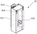
Fig. 18 is a schematic structural view of the lining lifting structure of the present invention.
Fig. 19 is a schematic structural view of the liner forming module and the liner moving module of the present invention.
Fig. 20 is a side view of fig. 19.
Fig. 21 is a schematic structural diagram of the terminal manipulator of the present invention.
Fig. 22 is a schematic structural diagram of a third rack of the present invention.
Fig. 23 is a schematic structural view of the half-closing action of the present invention.
Fig. 24 is a schematic structural view in another direction of fig. 23.
Fig. 25 is a schematic structural diagram of the first cover mechanism of the present invention.
Fig. 26 is a schematic structural view of the first cover mechanism and the packing box of the present invention.
Fig. 27 is a schematic structural view of the second cover mechanism of the present invention.
Fig. 28 is a schematic structural view of the third cover mechanism of the present invention.
Fig. 29 is a schematic structural view of the box rotating module of the present invention.
Fig. 30 is a schematic structural view of a fourth frame according to the present invention.
Fig. 31 is a schematic structural view of the labeling and positioning mechanism of the present invention.
Fig. 32 is a schematic structural view of the labeling manipulator of the present invention.
Detailed Description
In order to further explain the technical solution of the present invention, the present invention is explained in detail by the following embodiments.
In the description of the present invention, it is to be understood that the terms "center", "longitudinal", "lateral", "up", "down", "front", "back", "left", "right", "vertical", "horizontal", "top", "bottom", "inner", "outer", and the like indicate orientations or positional relationships based on the orientations or positional relationships shown in the drawings, and are only for convenience of description and simplicity of description, and do not indicate or imply that the device or element being referred to must have a particular orientation, be constructed and operated in a particular orientation, and therefore, should not be construed as limiting the present invention. In the description of the present invention, "a plurality" means two or more unless otherwise specified.
As shown in fig. 1 to 4, the present invention discloses an automatic packaging line of a network terminal, which includes a paper box feeding mechanism 10, an equipment frame 20, an adapter and network line feeding mechanism 30, a lining feeding mechanism 50, a terminal feeding mechanism 60, a box cover mechanism 70, a labeling mechanism 80 and a transmission mechanism 90.
As shown in fig. 1 and 2, the apparatus frame 20 is disposed at one end of the carton feeding mechanism 10, the apparatus frame 20 includes a first frame 21, a second frame 22, a third frame 23, and a fourth frame 24, which are disposed in parallel in sequence, the first frame 21, the second frame 22, and the fourth frame 24 are respectively provided with a moving module 25, as shown in fig. 5, each moving module 25 is disposed at an upper portion of the first frame 21, the second frame 22, and the fourth frame 24, each moving module 25 includes an X-axis slide rail 251, a Y-axis slide rail 252, a Z-axis slide rail 253, an X-axis slide block 254 slidably disposed on the X-axis slide rail 251, a Y-axis slide block 255 slidably disposed on the Y-axis slide rail 252, a Z-axis slide block 256 slidably disposed on the Z-axis slide rail 253, an X-axis cylinder 257 driving the X-axis slide block 254 to slide on the X-axis slide rail 251, and a Y-axis cylinder 258 driving the Y-axis slide block 255 to slide on the Y-axis, and a Z-axis cylinder 259 for driving the Z-axis slider 256 to slide on the Z-axis slide rail 253. In this embodiment, there are two X-axis slide rails 251 of each moving module 25, wherein one X-axis slide rail 251 is fixed at the left end of the first frame 21, the second frame 22 and the fourth frame 24, the other X-axis slide rail 251 is fixed at the right end of the first frame 21, the second frame 22 and the fourth frame 24 corresponding to the X-axis slide rail 251 at the left end, each X-axis slide rail 251 is matched with an X-axis slider 254, two ends of the Y-axis slide rail 252 are correspondingly locked on the X-axis sliders 254 of the two X-axis slide rails 251, the Y-axis slider 255 is longitudinally disposed at the front end of the Y-axis slide rail 252, the Z-axis slide rail 253 is fixedly disposed at the front end of the Y-axis slider 255, and the Z-axis slider 256 can move up and down along the Z-axis slide rail. The top ends of the first rack 21, the second rack 22, the third rack 23 and the fourth rack 24 are further provided with an indicator light 26 respectively, and the indicator light 26 is arranged at the top ends of the first rack 21, the second rack 22, the third rack 23 and the fourth rack 24.
As shown in fig. 1 to 4 in conjunction with fig. 6, the conveying mechanism 90 includes a conveying frame 91, a conveyor belt 92 disposed on the conveying frame 91, a plurality of stations 93 disposed on the conveyor belt 92, a plurality of sensors 94 disposed on the conveying frame 91 and located at one side of the conveyor belt 92, and a driving assembly 95 for controlling the transmission of the conveyor belt 92. The conveying frame 91 is disposed at the front ends of the carton feeding mechanism 10 and the apparatus frame 20, the conveying belt 92 may be an endless belt or an endless conveying chain (as shown in fig. 6), one end of the conveying belt 92 is located at the carton feeding mechanism 10, and the conveying direction of the conveying belt 92 is from the carton feeding mechanism 10 to the first frame 21, the second frame 22, the third frame 23, and the fourth frame 24 of the apparatus frame 20. A plurality of partitions 96 are secured to the conveyor belt 92 at equally spaced intervals to divide the belt into a plurality of said stations 93.
As shown in fig. 1 to 4 in combination with fig. 7, the carton feeding mechanism 10 includes an automatic carton folding machine 11 and a carton transferring mechanism 12, and the automatic carton folding machine 11 automatically folds a planar paperboard into a carton a with its top surface opened upward. With supporting net twine C of network terminal B, power adapter D, description E, inside lining F and network terminal B be in the utility model discloses in packing carton A is packed into from this packing carton A's top surface respectively under the cooperation of each mechanism. As shown in fig. 7, the paper cassette transfer mechanism 12 includes a transfer cylinder 121, a transfer turntable 122, a transfer suction rod 123 and a transfer suction cup 124, the transfer cylinder 121 is fixedly disposed at the top end of the conveying frame 91 of the conveying mechanism 90 and corresponds to the outlet of the automatic box folding machine 11, the transfer turntable 122 is rotatably disposed at the bottom of the transfer cylinder 121, the transfer suction rod 123 is fixedly engaged with the bottom of the transfer turntable 122, the transfer suction rod 124 is connected to the transfer suction rod 123 and connected to a vacuum tube, and the paper cassette transfer mechanism 12 rotates the transfer suction rod 123 to move the transfer suction cup 124 between the box folding machine and the conveyor belt 92 of the conveying mechanism 90. After the automatic box folding machine 11 folds the paper boards into the packing boxes a, the paper boxes are placed at one end of the box folding machine close to the conveying mechanism 90, the transferring sucker 124 of the paper box transferring mechanism 12 sucks the inner bottom surfaces of the packing boxes a, and the transferring air cylinder 121 drives the transferring turntable 122 to rotate, so that the transferring sucker 123 transfers the packing boxes a from the automatic box folding machine 11 to the conveying belt 92.
As shown in fig. 8 to 10, the adapter and cable feeding mechanism 30 is disposed in the first rack 21, and the adapter and cable feeding mechanism 30 includes a feeding and discharging module 31, a lifting module 32, a plastic sucking disc transfer module 33, an adapter and cable clamping jaw 34, a first rotating mechanism 35, and a cable adapter reshaping module 36.
As shown in fig. 11, the feeding and discharging module 31 is disposed at a lower portion of the first frame 21, the feeding and discharging module 31 includes a feeding mechanism 31A and a discharging mechanism 31B, the feeding mechanism 31A and the discharging mechanism 31B are disposed side by side, but the conveying direction is opposite, that is, the conveying direction of the feeding mechanism 31A is forward, and the conveying direction of the discharging mechanism 31B is backward. The feeding mechanism 31A includes a feeding fixing frame 311A, a feeding conveyor belt 312A, a feeding control motor 313A, and a feeding sensor 314A, the feeding fixing frame 311A is fixedly disposed on the first frame 21, a front idler pulley 315A is disposed in front of a top end of the feeding fixing frame 311A, a rear idler pulley 316A is disposed behind a top end of the feeding fixing frame 311A, and the feeding conveyor belt 312A is connected to the front idler pulley 315A and the rear idler pulley 316A and connected to the feeding control motor 313A. The discharging mechanism 31B comprises a discharging fixing frame 311B, a discharging conveying belt 312B, a discharging control motor 313B and a discharging sensor 314B, the feeding fixing frame 311B and the feeding fixing frame 311A are arranged on the first rack 21 side by side, a front idle wheel 315B is arranged in front of the top end of the discharging fixing frame 311B, a rear idle wheel 316B is arranged behind the top end of the discharging fixing frame 311B, and the discharging conveying belt 312B is connected with the front idle wheel 315B and the rear idle wheel 316B and connected with the discharging control motor 313B.
As shown in fig. 12, the lifting modules 32 include two sets, one lifting module 32 is disposed in front of the feeding mechanism 31A, and the other lifting module 32 is disposed in front of the discharging mechanism 31B. Each lifting module 32 comprises a lifting plate 321, a fixing plate 322, a sliding block 323, a motor shaft 324 and a connecting seat 325, the fixing plate 322 is fixedly arranged on the frame 21, the motor shaft 324 is longitudinally arranged on one side of the fixing plate 322 facing the feeding conveyer belt 312A or the discharging conveyer belt 312B, the sliding block 323 can slide up and down along the motor shaft 323, the connecting seat 325 is fixed on the sliding block 323 and can be linked with the sliding block 323, and the lifting plate 321 is fixed on the connecting seat 325. The upper portion of the fixing plate 322 is provided with a top sensor 326, the top sensor 326 is used for sensing the topmost position of the blister tray, the lower portion of the fixing plate 322 is provided with a bottom sensor 327, and the bottom sensor 327 is used for sensing the bottom position of the blister tray. The lifting plate 321 is disposed between the two feeding conveyer belts 312A of the feeding mechanism 31A, and the other lifting plate 321 is disposed between the two discharging conveyer belts 312B of the discharging mechanism 31B.
As shown in fig. 9 and 10, the plastic tray transferring module 33 includes a transverse slide rail 331, a longitudinal cylinder 332, a cylinder bracket 333, a slide 334 and a plastic tray suction cup 335, the transverse slide rail 331 is fixedly disposed above the first rack 21 corresponding to the feeding and discharging module 31, the slide 334 is slidably disposed on the transverse slide rail 331, one end of the cylinder bracket 333 is fixed on the slide 334, the other end is connected to the longitudinal cylinder 332, and the plastic tray suction cup 3355 is engaged with the bottom surface of the longitudinal cylinder 62.
As shown in fig. 13, the first rotating mechanism 35 is provided on the Z-axis slider 256 of the moving module 25 of the first frame 21. The first rotating mechanism 35 includes a fixed base 351, a rotating cylinder 352 fixedly fitted to the fixed base 351, and a rotating shaft 353 connected to the rotating cylinder 352. The fixed base 351 is fixedly engaged with the Z-axis slider 256 of the moving module 25 of the first frame 21.
As shown in fig. 14, the adapter and cable clamping jaw 34 includes an installation base 341, a clamping jaw cylinder 342, a cable clamping jaw 343, an adapter suction cup cylinder 344 and an adapter suction cup 345, the top surface of the installation base 341 is fixedly fitted with the bottom end of the rotating shaft 353 of the first rotating mechanism 35, the clamping jaw cylinder 342 is fixed on one side of the installation base 341 through a cylinder connecting plate 346, the cable clamping jaw 343 is openably and closably disposed on the clamping jaw cylinder 342, the adapter suction cup cylinder 344 is fixed on the other side of the installation base 341, and the adapter suction cup 345 is connected to the bottom end of the adapter suction cup cylinder 344 through a suction cup connecting plate.
As shown in fig. 15, the cable and adapter reshaping module 36 includes an air cylinder mounting plate 361, a lifting air cylinder 362, an adjusting air cylinder 363, a positioning plate 364 and an adjusting plate 365, wherein the air cylinder mounting plate 361 is fixedly disposed on the first frame 21, the lifting air cylinder 362 is fixedly disposed on the air cylinder mounting plate 361, the adjusting air cylinder 363 is fixedly disposed at the bottom end of the lifting air cylinder 362, the positioning plate 364 is fixed at one side of the adjusting air cylinder 363, and the adjusting plate 365 is fixed at the other side of the adjusting air cylinder 363 and can move along with the adjusting air cylinder 363.
The operation of the first frame 21 is as follows: the AGV trolley is used for placing a whole stack of plastic sucking discs provided with adapters and network cables on a feeding conveyer belt 312A of a feeding and discharging module 31A, after a feeding sensor 314A senses the plastic sucking discs, a feeding control motor 313A is started to control the conveyer belt 312A to convey forwards to a position close to one end of a lifting module 32 and stop, so that the plastic sucking discs are positioned above a lifting plate 321 of the lifting module 32 in front of a feeding mechanism 31A, a sliding block 323 of the lifting module 32 drives the lifting plate 321 to lift the whole stack of plastic sucking discs upwards, when a top sensor 326 of the lifting module 32 senses the top end of the plastic sucking discs, the sliding block 323 stops lifting, a moving module 25 of a first rack 21 drives a first rotating mechanism 35 and adapters and network cable clamping jaws 34 arranged on the first rotating mechanism 35 to move above the plastic sucking discs, so that the adapters are sucked by the adapters and the adapter sucking discs 345 of the network cables and the power cables of the adapters are clamped by the cable clamping jaws 343, and the network cable and the adapter are moved to the packaging box A on the first frame 21, the conveyor belt 92 is positioned in the packaging box A, the adapter sucker 345 and the cable clamp 343 are loosened, the conveyor belt 92 conveys the packaging box provided with the adapter and the network cable to the position below the network cable and adapter reshaping module 36, the lifting cylinder 362 is pressed downwards, the adjusting cylinder 363 outwards expands the positioning plate 364 and the adjusting plate 365 relatively, the lifting cylinder 362 is pressed downwards to the packaging box and then starts the adjusting cylinder 363 to retract, the adjusting plate 365 is driven to move towards the direction of the fixing plate 364, and the adapter and the network cable are fixed and adjusted at the fixed position of the packaging box A. After the adapter and the net string are loaded into the packing box a and the position is adjusted, the conveyor belt 92 continues to convey forward, and the next packing box a repeats the operation of loading the net string and the adapter.
After the net twine and the adapter in the plastic sucking disc at the topmost end of the lifting module 33 are emptied, the plastic sucking disc is moved to the longitudinal cylinder 332 of the module 33 and pressed downwards, so that the plastic sucking disc suction cup 335 sucks the empty plastic sucking disc, the longitudinal cylinder 332 drives the plastic sucking disc to ascend and move to one end of the discharging module 31B and descend again, the lifting module 32 corresponding to the discharging mechanism 31B ascends the lifting plate 321 to the top end sensor 326, the longitudinal cylinder 332 downwards presses the plastic sucking disc to be arranged on the lifting plate 321, and the lifting plate 321 drives the plastic sucking disc to descend to the top surface of the plastic sucking disc sensed by the top end sensor 326. When the plastic sucking discs are taken away gradually, the lifting plate 321 of the lifting module 32 corresponding to the feeding mechanism 31A rises gradually, the lifting plate 321 of the lifting module 32 corresponding to the discharging mechanism 31B descends gradually until all the network cables and adapters are taken away, the plastic sucking discs on one side of the feeding mechanism 31A are all transferred onto the lifting module 32 of the discharging mechanism 31B, the lifting module 32 on one side of the feeding mechanism 31A descends the lifting plate 321 to the bottom end sensor 327 to lift the next plastic sucking disc, the lifting module 32 on the corresponding discharging mechanism 31B descends the completely-stacked plastic sucking discs to the bottom end sensor 327, and the empty plastic sucking discs are transmitted to the AGV trolley from the discharging conveyer belt 312B of the discharging mechanism 31B backwards and are transplanted to the corresponding disc loading process through the AGV trolley.
As shown in fig. 16 to 20, the liner feeding mechanism 50 and the terminal feeding mechanism 60 are disposed in the second frame 22. The liner feeding mechanism 50 includes a liner lifting module 51, a liner forming module 52 and a liner moving module 53.
As shown in fig. 18, the liner lifting module 51 includes a liner stop 511, a liner support plate 512 and a lifting motor 513, the liner stop 511 is fixedly disposed at the bottom of the second frame 22, the lifting motor 513 is disposed at one side of the liner stop 511, and the liner support plate 512 is slidably disposed at the lifting motor 513. The lining paper sheets are stacked on the lining support plate 512, and the upper portion of the lining baffle 511 is provided with a sensor 514.
The lining moving module 53 comprises a fixed slide rail 531, a cylinder support 532, a lining cylinder 533 and a lining suction cup 534, the fixed slide rail 531 is transversely arranged on the second rack 22 along the front end and the rear end of the second rack 22 and is located above the lining lifting module, the cylinder support 532 is slidably arranged on the fixed slide rail 531, the lining cylinder 533 is longitudinally arranged on the cylinder support 532, and the lining suction cup 534 is fixedly arranged on the bottom surface of the lining cylinder 533.
The lining forming module 52 comprises an upper die 521, a lower die 522 and a lower pressing module 523, the upper die comprises a forming cylinder 52A, a lower pressing plate 52B fixedly arranged at the bottom of the forming cylinder 52A, an upper inclined plate 52C fixedly arranged at one side of the lower pressing plate 52B, a bending plate 52D fixedly arranged at the other side of the lower pressing plate 52B, a lower pressing shaping plate 52E connecting the upper inclined plate 52C and the bending plate 52D, and a pen-shaped cylinder 52F arranged at the other side of the bending plate 52D, the forming cylinder 52A is longitudinally arranged on a cylinder support 532 of the lining moving module 53, a gap for the lining cylinder 533 and the lining suction cup 534 of the lining moving module 53 to pass through is formed at the middle part of the lower pressing shaping plate 52D, sponge pads are respectively arranged at the bottom surfaces of the upper inclined plate 52C and the lower pressing shaping plate 52E, the lower shaping plate 52E is L-shaped, and the lower shaping plate 52 is further provided with a suction nozzle 52G.
The lower mould includes left supporting mechanism 524 and right supporting mechanism 525, left supporting mechanism 524 includes left mounting panel 52H, left jacking cylinder 52I and left support plate 52J, left side mounting panel 52H is fixed to be set up on second frame 22, left jacking cylinder 52I is fixed to be set up on left mounting panel 52H, left support plate 52J is fixed to be set up on left jacking cylinder 52I, left support plate 52J is equal with the lower pressure stereotype 52E width of last mould 521, and left support plate 52J's top surface is connected with suction nozzle and sponge, the suction nozzle sets up the center at the sponge. Right supporting mechanism 525 includes right mounting panel 52K, right jacking cylinder 52L and down swash plate 52M, and right mounting panel 52K is fixed to be set up on second frame 22 corresponding with left mounting panel 52H, and is located left mounting panel 52H's right side, and right jacking cylinder 52L is fixed to be set up on right mounting panel 52K, down swash plate 52M is fixed to be set up on right jacking cylinder 52L.
When the packing box with the mesh wire and the adaptor is transferred from the conveyor belt 92 at the front end of the first frame 21 to the front end of the second frame 22, the sensor 94 arranged on the transmission frame 91 senses that the packing box a is moved to the right position, the conveyor belt 92 stops transferring, the lining lifting module 51 of the lining feeding mechanism 50 lifts up the lining paper board, the lining cylinder 533 of the lining moving module 53 sucks the lining paper board and simultaneously drives the upper die 521 to move the lining paper board to the position corresponding to the lower die 522 of the upper die 521, the forming cylinder 52A of the upper die 521 carries the upper inclined plate 52C, the bending plate 52D and the lower pressing and shaping plate 52 to press the lining paper board down to the lower die 522, the suction cup on the left support plate 52J of the lower die 522 sucks the lining paper board, and the upper inclined plate 52C, the bending plate 52D, the lower pressing and shaping plate 52E and the pen-shaped cylinder 52F of the upper die 521 simultaneously press the lining paper board down, the L-shaped folding angle of the downward-pressing shaping plate 52E forms a first bending part on the right side of the lining paper board corresponding to the left support plate 52J, a second bending part is formed between the lower inclined plate 52M and the bottom ends of the upper inclined plate 52C and the downward-pressing shaping plate 52E, the lining paper board on the left side of the left support plate 52J is pressed downward by the bending plate 52D to form a third bending part, and the pen-shaped air cylinder 52F further presses down the third bending part for shaping to complete the bending and shaping of the lining paper board. The bent lining paper board is sucked by the lining sucker 534 of the lining moving module 53 and moves forward, the formed lining F is placed into the packaging box a on the conveyor belt 92, and the left bending area of the lining F covers the power adapter and the network cable.
The terminal feeding mechanism 60 includes a terminal manipulator 61 and a second rotating mechanism 62, the second rotating mechanism 62 has the same structure as the first rotating mechanism 35, and the second rotating mechanism 62 is disposed on the Z-axis slider 256 of the moving module 25 of the second frame 22.
As shown in fig. 21, the terminal manipulator 61 includes a joint 611, a support 612, a shaft plate 613, an inclined pushing cylinder 614, a pushing plate 615, an adjusting plate 616, a clamping cylinder 617, a terminal suction cup 618 and a terminal clamping jaw 619, the joint 611 is fixedly fitted on a rotating shaft 623 (shown in fig. 16) of the second rotating mechanism 62, the joint 611 is fixedly fitted with one end of the shaft plate 613, the other end of the shaft plate is fixedly fitted with the inclined pushing cylinder 614, the bottom end of the inclined pushing cylinder 614 is connected with the pushing plate 615, one end of the shaft plate 613, which is connected with the joint 611, is pivoted on the support 612, the support 612 is fixedly fitted with the adjusting plate 616, the adjusting plate 616 is provided with a long groove a, the pushing plate 615 is slidably disposed in the long groove 616A, one end of the adjusting plate 616 is fixed on the clamping cylinder 617, the clamping cylinder 617 is disposed on the terminal suction cup 618, and the bottom surface, terminal clamping jaw 619 includes a stationary dog 619A and an adjusting claw 619B, and stationary dog 619A is fixed to be set up in one side of terminal sucking disc 619, and adjusting claw 619B connects press from both sides and get cylinder 617, and the flexible adjusting claw 619B that drives through pressing from both sides cylinder 617 unclamps or presss from both sides tight network terminal B.
When the network terminal B packed by the packing bag is transferred to the second rack 22 from a pallet line (not shown, the transfer direction of the pallet line is the same as the transfer direction of the conveyor belt 92 of the conveying mechanism 90, in a previous process of the conveying mechanism 90, the network terminal B has completed a bagging action, and a specification E is placed on the top surface of each network terminal B), the transfer is stopped, the moving module 25 of the second rack 22 drives the terminal feeding mechanism 60 to move to the upper side of the pallet line, the clamping cylinder 617 of the terminal manipulator 61 drives the adjusting claw 619B of the terminal clamping claw 619 to open to the two sides of the network terminal B and then to contract, so as to clamp the network terminal B, the terminal sucker 618 sucks the specification E placed on the top surface of the network terminal B to clamp the network terminal B and the specification E at the same time, the moving module 25 of the second rack 22 drives the terminal clamping B and the terminal manipulator 61 sucking the specification to move to the packing box a Above, the inclined pushing cylinder 614 pushes the pushing plate 615 downward, so that the pushing plate 615 moves from one end of the elongated slot 616A of the adjusting plate 616 to the other end, the support 612 pivoted to the shaft plate 613 drives the adjusting plate 616, the clamping cylinder 617, the terminal suction cup 618 and the terminal clamping jaw 619 to be arranged in an inclined manner, so that the opening of the packaging bag sleeved outside the network terminal B is inclined downward, and when the network terminal B packaged by the terminal manipulator 61 is placed into the packaging box a, the opening of the packaging bag is pressed into the packaging box a.
As shown in fig. 22, the lid mechanism 70 is disposed in the third frame 23, the third frame 23 is further provided with a box body rotating module 40 on a side of the lid mechanism 70 close to the fourth frame 24, the lid mechanism 70 includes a first lid mechanism 71, a second lid mechanism 72 and a third lid mechanism 73, and as shown in fig. 23 and 24, the first lid mechanism 71 and the second lid mechanism 72 cooperate to complete a half-closing action.
As shown in fig. 25 and fig. 26, the first box cover mechanism 71 includes a bottom plate 71A, two box cover slide rails 71B disposed on two sides of the bottom plate 71A, a slide plate 71C slidably disposed on the two box cover slide rails 71B, two clamp plates 71D disposed on two sides of one end of the slide plate 71C, a position limiting plate 71E disposed between the two clamp plates 71D, a cover pushing plate 71F pivotally connected to a rear end of the position limiting plate 71E, a box cover cylinder 71G disposed on a middle upper portion of one end of the cover pushing plate 71F away from the packing box a, guide lugs 71H disposed on two sides of the cover pushing plate 71F, a two-way cylinder 71I connecting the two guide lugs 71H, a base 71J supporting the two-way cylinder 71I, and a slide plate cylinder 71K pushing the slide plate 71C to slide back and forth, one end of the box cover cylinder 71G is connected to the cover pushing plate 71F, the other end is pivotally connected to an auxiliary rod 71L, the bottom plate 71A is fixed to the third frame 23 and corresponds to the conveyor belt 92 of the conveyor mechanism 90.
As shown in fig. 27, the second lid mechanism 72 includes a fixed supporting plate 721, the fixed supporting plate 721 is fixedly disposed on the third frame 23, a pivot 722 is disposed on a bottom surface of one end of the fixed supporting plate 721, a locking plate 723 corresponding to the pushing cover plate 71F of the first lid mechanism 71 is pivotally connected to the pivot 722, a linking plate 724 is pivotally connected to the pivot 722, a second lid cylinder 725 is pivotally connected to a top surface of the other end of the fixed supporting plate 721, one end of the second lid cylinder 725 is pivotally connected to the fixed supporting plate 721, and the other end is pivotally connected to the linking plate 724.
As shown in fig. 28, the third lid covering mechanism 73 includes a cylinder fixing plate 731, a guide block depressing cylinder 732 disposed on one side of the cylinder fixing plate 731, a lid depressing cylinder 733 disposed on the other side of the cylinder fixing plate 731, a guide block support plate 734 disposed on the bottom surface of the guide block depressing cylinder 732, a lid guide block 735 and a suction cup 736 disposed on both sides of the guide block support plate 734, a lid support plate 737 disposed below the lid depressing cylinder 733, and a pushing cylinder 738 connected to the lid support plate 737, wherein the lid support plate 737 is disposed between the two lid depressing guide blocks 735, and the cylinder support plate 731 is fixedly disposed on the third frame 23.
When the packing box a provided with the net wire C, the adapter D, the lining E, the network terminal B and the specification E is transferred from the second frame 22 to the first box cover mechanism 71 and the second box cover mechanism 72 of the third frame 23, the slide plate cylinder 71K of the first box cover mechanism 71 drives the slide plate 71C to move toward the packing box a, so that the stopper plate 71E and the push cover plate 71F abut against the packing box a, the two clamp plates 71D clamp both sides of the packing box a, the push cover plate 71F abuts against the outside of the vertical side of the packing box a, the clamp plate 723 of the second box cover mechanism 72 abuts against the inside of the vertical side of the packing box a, the box cover cylinder 71G advances forward, the second box cover cylinder 725 and the box cover cylinder 71G synchronously operate, the box cover of the packing box a is gradually pressed down, when the box cover is pressed down, the lug plates on both sides of the box cover are limited by the two guide lug plates 71H to be bent, and the box cover of the box a is, the two lugs of the box cover are pressed into the packing box, and the top surface of the box cover is covered on the packing box to complete the action of half box cover.
The packing box a after the half-closing action is continuously conveyed to the third box cover mechanism 73 from the conveying belt 92, the pushing cylinder 738 of the third box cover mechanism 73 pushes the box cover of the packing box a forwards to enable the box cover to be clamped on the box cover supporting plate 737, the two edge-closing guide blocks 735 bend the lugs on two sides of the box cover of the packing box a downwards under the action of the guide block pressing cylinder 732, meanwhile, the sucking discs 736 suck two sides of the packing box a, the pushing cylinder 738 retracts backwards to enable the box cover to be separated from the box cover 737, the box cover pressing cylinder 733 presses the part protruding out of the packing box to the front of the packing box a downwards, and under the limiting and guiding action of the two edge-closing guide blocks 735, the two lugs are clamped into two sides of the packing box to complete the box cover action.
As shown in fig. 29, the cartridge rotating unit 40 includes a rotating fixing plate 41, a rotating unit cylinder 42 fixedly fitted to the bottom surface of the rotating fixing plate 41, a rotating plate 43 provided on the rotating unit cylinder 42, and a rotating suction cup 44 provided on the bottom surface of the rotating plate 43. The rotary sucker 44 sucks the package box A after the box cover, and the rotary cylinder 42 drives the rotary disk 43 and the rotary sucker 44 to rotate 90 degrees, so that the package box can perform subsequent labeling actions.
As shown in fig. 30, the labeling mechanism 80 is provided in the fourth frame 24, the labeling mechanism 80 includes a labeling machine 81, a labeling positioning mechanism 82, a third rotating mechanism 83, and a labeling robot 84, the labeling machine 81 is provided on the fourth frame 24, and the labeling positioning mechanism 82 is provided on the fourth frame 24 so as to correspond to a position above the conveyor belt 92. As shown in fig. 31, the labeling positioning mechanism 82 includes a positioning frame 821 and a labeling adjusting cylinder 822, the third rotating mechanism 83 is disposed on the Z-axis slider 256 of the moving module 25 of the fourth frame 24, and the structure of the third rotating mechanism 83 is the same as that of the first rotating mechanism 35. As shown in fig. 32, the labeling robot 84 includes a connection joint 841, a labeling rotary cylinder 842, a rotary rod 843 and a labeling suction cup 844, the connection joint 841 is fixedly matched with the rotary shaft 833 of the third rotary mechanism 83, the connection joint 841 is fixedly matched with the labeling rotary cylinder 842, the rotary rod 843 is fixed on the rotary disk of the labeling rotary cylinder 842, and the labeling suction cup 844 is fixedly matched with the bottom surface of the rotary rod 843.
Packing carton A behind the lid conveys to the fourth machine 24 in through rotatory back of box body rotation module 4, the sensor sensing stops conveying behind the packing carton A, the location frame of subsides mark positioning mechanism 82 fixes a position packing carton A, and adjust through pasting mark adjustment cylinder 822, ensure that packing carton A is located the position of setting for, labeling manipulator 84 drives labeling manipulator 84 through the removal module 25 of fourth frame 24 and removes to the play mark position department of marking machine 81 and absorb the label, remove again to packing carton A's subsides mark position department, and push down through removing module 25 and paste the label in packing carton A's mark position department. After the labeling operation is completed, the conveyor belt 92 conveys the packaging box a to the weighing mechanism for weighing.
The above embodiments and drawings are not intended to limit the form and style of the present invention, and any suitable changes or modifications made by those skilled in the art should not be construed as departing from the scope of the present invention.
Claims (11)
1. An automatic packaging line for network terminals, comprising: the automatic labeling device comprises an equipment frame, a paper box feeding mechanism, an adapter and net wire feeding mechanism, a lining feeding mechanism, a terminal feeding mechanism, a box cover mechanism, a labeling mechanism and a transmission mechanism; the equipment frame is arranged at one end of the paper box feeding mechanism, the adapter and mesh wire feeding mechanism, the lining feeding mechanism, the terminal feeding mechanism, the box cover mechanism and the labeling mechanism are sequentially arranged on the equipment frame, and the transmission mechanism is arranged at the front ends of the paper box feeding mechanism and the equipment frame; the equipment frame comprises a first frame, a second frame, a third frame and a fourth frame which are sequentially arranged side by side, wherein the first frame, the second frame and the fourth frame are respectively provided with a movable module, each movable module is connected with a rotating mechanism, an adapter and a network cable feeding mechanism are arranged in the first frame, a lining feeding mechanism and a terminal feeding mechanism are arranged in the second frame, a box cover mechanism is arranged in the third frame, a labeling mechanism is arranged in the fourth frame, the paper box feeding mechanism is arranged on one side of the first frame, which deviates from the second frame, and the conveying direction of the conveying mechanism is transmitted from the paper box feeding mechanism to the first frame, the second frame, the third frame and the fourth frame of the equipment frame.
2. The automatic packaging line of a network terminal according to claim 1, characterized in that: the conveying mechanism comprises a conveying frame, a conveying belt arranged on the conveying frame, a plurality of stations arranged on the conveying belt, a plurality of sensors arranged on the conveying frame and located on one side of the conveying belt, and a driving assembly for controlling transmission of the conveying belt, the conveying frame is arranged at the front ends of the paper box feeding mechanism and the equipment frame, a plurality of partition plates are fixed on the conveying belt at equal intervals, and the conveying belt is divided into a plurality of stations.
3. The automatic packaging line of a network terminal according to claim 1, characterized in that: the carton loading mechanism comprises an automatic carton folding machine and a carton transferring mechanism, the carton transferring mechanism comprises a transferring cylinder, a transferring rotary table, a transferring suction rod and a transferring sucker, the transferring cylinder is fixedly arranged at the top end of a transmission frame of the transmission mechanism and corresponds to an outlet of the automatic carton folding machine, the transferring rotary table is rotatably arranged at the bottom of the transferring cylinder, the transferring suction rod is fixedly matched with the bottom of the transferring rotary table, the transferring sucker is connected with the transferring suction rod and connected with a vacuum tube, and the carton transferring mechanism enables the transferring sucker to move between a conveyor belt of the carton folding machine and the conveyor mechanism by rotating the transferring suction rod.
4. The automatic packaging line of a network terminal according to claim 1, characterized in that: adapter and net twine feed mechanism includes business turn over material module, lifting module, adapter and net twine clamping jaw and net twine adapter plastic module, business turn over material module sets up in first frame, and the lifting module sets up the one end at business turn over material module, adapter and net twine clamping jaw set up on the rotary mechanism of the removal module of first frame, and net twine adapter plastic module sets up in first frame.
5. The automatic packaging line of a network terminal according to claim 4, characterized in that: adapter and net twine clamping jaw include mount pad, clamping jaw cylinder, line clamping jaw, adapter sucking disc cylinder and adapter sucking disc, the top surface of mount pad is in the same place with first rotary mechanism's rotation axis bottom fixed fit, and the clamping jaw cylinder passes through the cylinder connecting plate to be fixed in one side of mount pad, and the setting that the fastener claw can open and shut is on the clamping jaw cylinder, and adapter sucking disc cylinder is fixed at the opposite side of mount pad, and the adapter sucking disc passes through the sucking disc connecting plate to be connected in the bottom of adapter sucking disc cylinder.
6. The automatic packaging line of a network terminal according to claim 4, characterized in that: the net twine and adapter plastic module includes cylinder mounting panel, lift cylinder, adjustment cylinder, locating plate and regulating plate, the cylinder mounting panel is fixed to be set up in first frame, and the lift cylinder is fixed to be set up on the cylinder mounting panel, and the fixed bottom that sets up at the lift cylinder of adjustment cylinder, locating plate are fixed in one side of adjustment cylinder, and the regulating plate is fixed and can be removed along with the adjustment cylinder at the opposite side of adjustment cylinder.
7. The automatic packaging line of a network terminal according to claim 4, characterized in that: the business turn over material module includes feed mechanism and discharge mechanism, and feed mechanism is and sets up side by side with discharge mechanism, but direction of transfer is opposite, adapter and net twine feed mechanism still includes that the plastic uptake dish moves and carries the module, and the plastic uptake dish moves and carries the module and include horizontal slide rail, vertical cylinder, cylinder support, slide and plastic uptake dish sucking disc, horizontal slide rail is fixed to be set up in the top that first frame corresponds business turn over material module, and slide slidable sets up on horizontal slide rail, and the one end of cylinder support is fixed on the slide, and vertical cylinder is connected to the other end, the cooperation of plastic uptake dish sucking disc is in the bottom surface of vertical cylinder.
8. The automatic packaging line of a network terminal according to claim 1, characterized in that: the lining feeding mechanism comprises a lining lifting module, a lining forming module and a lining moving module, the lining lifting module is arranged at the rear end of the first rack, the lining moving module is arranged on the first rack and is positioned above the lining lifting module, the lining forming module comprises an upper die and a lower die, the upper die and the lining moving module are combined together, and the lower die is arranged on the first rack and is positioned below the upper die; the lining lifting module comprises a lining baffle, a lining support plate and a lifting motor, wherein the lining baffle is fixedly arranged at the bottom of the second rack, the lifting motor is arranged on one side of the lining baffle, the lining support plate is slidably arranged on the lifting motor, and a sensor is arranged at the upper part of the lining baffle; the inside lining removes module includes fixed slide rail, cylinder support, inside lining cylinder and inside lining sucking disc, fixed slide rail transversely sets up in the second frame and is located along the front and back end of second frame the top position of inside lining lifting module, cylinder support slidable sets up on fixed slide rail, and the inside lining cylinder vertically sets up on cylinder support, and the fixed bottom surface that sets up at the inside lining cylinder of inside lining sucking disc.
9. The automatic packaging line of a network terminal according to claim 8, characterized in that: the upper die of the lining forming module comprises a forming cylinder, a lower pressing plate fixedly arranged at the bottom of the forming cylinder, an upper inclined plate fixedly arranged on one side of the lower pressing plate, a bending plate fixedly arranged on the other side of the lower pressing plate, a lower pressing shaping plate connecting the upper inclined plate and the bending plate and a pen-shaped cylinder arranged on the other side of the bending plate, wherein the forming cylinder is longitudinally arranged on a cylinder support of the lining moving module, a gap for the lining cylinder and the lining sucker of the lining moving module to pass through is formed in the middle of the lower pressing shaping plate, sponge pads are respectively arranged on the bottom surfaces of the upper inclined plate and the lower pressing shaping plate, the lower pressing shaping plate is L-shaped, and a suction nozzle is also arranged on the lower pressing shaping plate; the lower die of the lining forming module comprises a left supporting mechanism and a right supporting mechanism, the left supporting mechanism comprises a left mounting plate, a left jacking cylinder and a left supporting plate, the left mounting plate is fixedly arranged on the second machine, the left jacking cylinder is fixedly arranged on the left mounting plate, the left supporting plate is fixedly arranged on the left jacking cylinder, the widths of the left supporting plate and a pressing shaping plate of the upper die are equal, the top surface of the left supporting plate is connected with a suction nozzle and a sponge, and the suction nozzle is arranged in the center of the sponge; the right supporting mechanism comprises a right mounting plate, a right jacking cylinder and a lower inclined plate, the right mounting plate is fixedly arranged on the second frame and corresponds to the left mounting plate, the right mounting plate is located on the right side of the left mounting plate, the right jacking cylinder is fixedly arranged on the right mounting plate, and the lower inclined plate is fixedly arranged on the right jacking cylinder.
10. The automatic packaging line of a network terminal according to claim 1, characterized in that: the terminal feeding mechanism comprises a terminal manipulator, the terminal manipulator comprises a joint, a support, a shaft plate, an inclined pushing cylinder, a pushing plate, an adjusting plate, a clamping cylinder, a terminal sucker and a terminal clamping jaw, the joint is fixedly matched with a rotating shaft of the second rotating mechanism, the joint is fixedly matched with one end of the shaft plate, the other end of the shaft plate is fixedly matched with the inclined pushing cylinder, the bottom end of the inclined pushing cylinder is connected with the pushing plate, one end of the shaft plate, which is connected with the joint, is pivoted on the support, the support is fixedly matched with the adjusting plate, an elongated slot is formed in the adjusting plate, the pushing plate is slidably arranged in the elongated slot, one end of the adjusting plate is fixed on the clamping cylinder, the clamping cylinder is arranged on the terminal sucker, a plurality of suction nozzles are arranged on the bottom surface of the terminal sucker, the terminal clamping jaw comprises a fixing jaw and an adjusting jaw, and, the adjusting claw is connected with the clamping cylinder.
11. The automatic packaging line of a network terminal according to claim 1, characterized in that: the box cover mechanism comprises a first box cover mechanism and a third box cover mechanism, and the first box cover mechanism is arranged at the front end of the third box cover mechanism in the conveying direction corresponding to the conveying mechanism; the first box cover mechanism comprises a bottom plate, two box cover slide rails arranged on two sides of the bottom plate, a slide plate slidably arranged on the two box cover slide rails, two clamp plates arranged on two sides of one end of the slide plate, a limiting plate arranged between the two clamp plates, a push cover plate pivoted at the rear end of the limiting plate, a box cover cylinder arranged on the middle upper part of one end of the push cover plate, which is far away from the packing box, guide lug plates arranged on two sides of the push cover plate, two-way cylinders connected with the two guide lug plates, a base supporting the two-way cylinders, and a slide plate cylinder pushing the slide plate to slide forwards and backwards, wherein one end of the box cover cylinder is connected with the push cover plate, the other end of the box cover cylinder is pivoted on an auxiliary support rod, the auxiliary support rod; the third lid mechanism includes cylinder fixed plate, sets up guide block push down cylinder in cylinder fixed plate one side, sets up the lid push down cylinder at cylinder fixed plate opposite side, sets up guide block fagging of pushing down the cylinder bottom surface at the guide block, sets up the limit guide block and the sucking disc that close in guide block fagging both sides, sets up lid fagging of lid push down cylinder below, connects the propulsion cylinder of lid fagging, the lid fagging is located two and closes between the limit guide block, and the fixed setting of cylinder backup pad is in the third frame.
Priority Applications (1)
| Application Number | Priority Date | Filing Date | Title |
|---|---|---|---|
| CN201922273084.7U CN211711172U (en) | 2019-12-17 | 2019-12-17 | Automatic packaging line of network terminal |
Applications Claiming Priority (1)
| Application Number | Priority Date | Filing Date | Title |
|---|---|---|---|
| CN201922273084.7U CN211711172U (en) | 2019-12-17 | 2019-12-17 | Automatic packaging line of network terminal |
Publications (1)
| Publication Number | Publication Date |
|---|---|
| CN211711172U true CN211711172U (en) | 2020-10-20 |
Family
ID=72816211
Family Applications (1)
| Application Number | Title | Priority Date | Filing Date |
|---|---|---|---|
| CN201922273084.7U Active CN211711172U (en) | 2019-12-17 | 2019-12-17 | Automatic packaging line of network terminal |
Country Status (1)
| Country | Link |
|---|---|
| CN (1) | CN211711172U (en) |
Cited By (2)
| Publication number | Priority date | Publication date | Assignee | Title |
|---|---|---|---|---|
| CN110963116A (en) * | 2019-12-17 | 2020-04-07 | 厦门宏泰智能制造有限公司 | Automatic packaging line of network terminal |
| CN110963116B (en) * | 2019-12-17 | 2024-05-03 | 厦门宏泰智能制造有限公司 | Automatic packaging line of network terminal |
-
2019
- 2019-12-17 CN CN201922273084.7U patent/CN211711172U/en active Active
Cited By (2)
| Publication number | Priority date | Publication date | Assignee | Title |
|---|---|---|---|---|
| CN110963116A (en) * | 2019-12-17 | 2020-04-07 | 厦门宏泰智能制造有限公司 | Automatic packaging line of network terminal |
| CN110963116B (en) * | 2019-12-17 | 2024-05-03 | 厦门宏泰智能制造有限公司 | Automatic packaging line of network terminal |
Similar Documents
| Publication | Publication Date | Title |
|---|---|---|
| CN110816959B (en) | Automatic packaging method of network terminal | |
| CN211766668U (en) | Three-degree-of-freedom unpacking, packing and sealing integrated machine | |
| CN110816923A (en) | Cover closing equipment for packaging box | |
| CN111017333A (en) | Lining forming mechanism of packing carton | |
| CN113860053B (en) | Automatic paste beautiful line of battery and glue equipment | |
| CN211711172U (en) | Automatic packaging line of network terminal | |
| CN107098021B (en) | Battery packaging line | |
| CN110963116B (en) | Automatic packaging line of network terminal | |
| CN217864895U (en) | Full-automatic carton closing device | |
| CN211365039U (en) | Automatic boxing equipment for adapter and network cable | |
| CN110963116A (en) | Automatic packaging line of network terminal | |
| CN217073534U (en) | Full-automatic leather case edge covering equipment | |
| CN218704477U (en) | Automatic chain loading equipment for saw chain | |
| CN111792097A (en) | Three-degree-of-freedom unpacking, packing and sealing integrated machine | |
| CN211365091U (en) | Automatic feeding and discharging equipment for power adapter | |
| CN211310114U (en) | Manipulator of power adapter | |
| CN211365165U (en) | Lining forming mechanism of packing carton | |
| CN112407427A (en) | PCB circuit board packagine machine | |
| CN211253131U (en) | Cover closing equipment for packaging box | |
| CN110683147A (en) | SMD material automatic labeling and boxing equipment | |
| CN114311833B (en) | Forming device for box package paper in six-side box | |
| CN217626277U (en) | Small piece assembly line | |
| CN115465528B (en) | Automatic tray packaging line and tray bagging mechanism thereof | |
| CN210116669U (en) | POS machine automatic assembly line | |
| CN217260805U (en) | File jacket bag packaging machine |
Legal Events
| Date | Code | Title | Description |
|---|---|---|---|
| GR01 | Patent grant | ||
| GR01 | Patent grant |