CN211612069U - Gear drive gas purification device - Google Patents
Gear drive gas purification device Download PDFInfo
- Publication number
- CN211612069U CN211612069U CN202020022550.4U CN202020022550U CN211612069U CN 211612069 U CN211612069 U CN 211612069U CN 202020022550 U CN202020022550 U CN 202020022550U CN 211612069 U CN211612069 U CN 211612069U
- Authority
- CN
- China
- Prior art keywords
- water
- box body
- gear
- shaft
- flange
- Prior art date
- Legal status (The legal status is an assumption and is not a legal conclusion. Google has not performed a legal analysis and makes no representation as to the accuracy of the status listed.)
- Expired - Fee Related
Links
- 238000000746 purification Methods 0.000 title claims abstract description 38
- XLYOFNOQVPJJNP-UHFFFAOYSA-N water Substances O XLYOFNOQVPJJNP-UHFFFAOYSA-N 0.000 claims abstract description 289
- 230000005540 biological transmission Effects 0.000 claims abstract description 93
- 239000003595 mist Substances 0.000 claims abstract description 88
- 239000007921 spray Substances 0.000 claims abstract description 49
- 239000000779 smoke Substances 0.000 claims abstract description 14
- 230000002265 prevention Effects 0.000 claims abstract description 12
- 238000000926 separation method Methods 0.000 claims abstract description 9
- 238000005507 spraying Methods 0.000 claims abstract description 9
- 238000000889 atomisation Methods 0.000 claims abstract description 5
- 238000000034 method Methods 0.000 claims abstract description 5
- 238000007599 discharging Methods 0.000 claims description 4
- 238000007789 sealing Methods 0.000 claims description 3
- 238000012423 maintenance Methods 0.000 claims 2
- 239000002699 waste material Substances 0.000 abstract description 8
- 230000000694 effects Effects 0.000 abstract description 6
- 230000007613 environmental effect Effects 0.000 abstract description 6
- 125000004122 cyclic group Chemical group 0.000 abstract description 5
- 238000009423 ventilation Methods 0.000 abstract description 3
- 239000007789 gas Substances 0.000 description 26
- 239000000428 dust Substances 0.000 description 4
- 238000002156 mixing Methods 0.000 description 4
- 238000011084 recovery Methods 0.000 description 4
- 235000013361 beverage Nutrition 0.000 description 3
- 235000019504 cigarettes Nutrition 0.000 description 3
- 238000000605 extraction Methods 0.000 description 3
- 239000003517 fume Substances 0.000 description 3
- 238000005272 metallurgy Methods 0.000 description 3
- 230000009286 beneficial effect Effects 0.000 description 2
- 238000005352 clarification Methods 0.000 description 2
- 239000010802 sludge Substances 0.000 description 2
- 239000012141 concentrate Substances 0.000 description 1
- 230000007547 defect Effects 0.000 description 1
- 238000009434 installation Methods 0.000 description 1
- 239000000463 material Substances 0.000 description 1
- -1 meanwhile Substances 0.000 description 1
- 239000000203 mixture Substances 0.000 description 1
- 239000008213 purified water Substances 0.000 description 1
- 238000005406 washing Methods 0.000 description 1
- 239000002351 wastewater Substances 0.000 description 1
Images


Abstract
The utility model relates to a gaseous purifier of gear drive, its characterized in that: the water mist spraying device is composed of a gear transmission box body, a water mist box body and a water collecting box body; the method comprises the following steps: the gear transmission device, the spray atomization exhaust facility and the water-gas separation exhaust facility realize the functions of purification, fire prevention and oil smoke discharge. The utility model provides a traditional electrostatic purification equipment power consumption big, waste oil mud is difficult for retrieving, the fire prevention effect is poor, the problem of conflagration takes place easily, the accessible sprays the combined action of purification, because exhaust air-purifying, be close to the room temperature relatively, and can add ventilation air with the air-purifying emission that is fit for, as work tonifying wind, the use of air conditioner has been reduced, increase the fire prevention function, improve cyclic utilization, the energy can be saved, save money, the equipment function has been increased, environmental protection equipment availability factor has been improved.
Description
Technical Field
The utility model belongs to an environmental protection clarification plant that is used for fields such as metallurgy, mine, enterprise and food and beverage to carry out smoke and dust emission, in particular to gear drive gas purification device.
Background
At present, the environmental protection clarification plant that smoke and dust discharged is carried out in fields such as domestic metallurgy, mine, mill, food and beverage, the tradition adopts spray water collection petticoat pipe and exhaust fan to add the electrostatic cleaner and through a large amount of pipe connection group into oil extraction cigarette clean system among the prior art, reaches oil extraction cigarette and purification purpose, and this kind of clean system that discharges fume exists: the application equipment and the material are more, the power consumption is big, extravagant pipeline, extravagant a large amount of manual work installation costs, and comprehensive utilization is low, and waste oil mud is difficult for retrieving, and the fireproof effect is poor, and later stage washing oil smoke is maintained and waste water recovery is inconvenient, cyclic utilization inefficiency scheduling problem.
Disclosure of Invention
The utility model overcomes the above-mentioned defect that exists, the purpose is for solving fields such as metallurgy, mine, enterprise and food and beverage and carrying out the electrostatic purification equipment that the smoke and dust discharged, the function singleness, the fire prevention effect is poor and comprehensive utilization is low, utilize spray water to atomize and purify and add the combination of smoke cover, improve and purify, fire prevention and oil extraction cigarette function, the recovery processing can be concentrated to the purification water, waste oil mud is easily retrieved, improve environmental protection cyclic utilization, the energy can be saved, the equipment investment can be saved etc., provide a gear drive gas purification device.
The content of the gear transmission gas purification device of the utility model is briefly described as follows:
the utility model discloses gaseous purifier of gear drive, by the gear drive box, the water smoke box, receive the water box, gear box access cover, including a motor, an end cap, a controller, and a cover plate, the water smoke box flange, the gear box flange, receive the water box flange, the spray pipe connecting pipe, the wash port, the bolt, motor base, the main base, the screw, sealed lid, the motor flange dish, final drive shaft, a bearing, the cavity bracing piece that closes, the pinion shaft, the pinion gear, the rotating shaft gear, main drive gear, the gear box protecgulum, preceding rotating shaft, the back rotating shaft, receive the water tank axle, the water smoke tank axle, the axle connects the ring flange, receive the water grid, receive the water tank breakwater, the muddy water piece, the spray pipe, the water spout, the water smoke tank breakwater, the umbrella lid, the fixed support pole, impeller piece group, the honeycomb grid: the gear transmission gas purification device consists of a gear transmission box body, a water mist box body and a water collection box body; the method comprises the following steps: the gear transmission device, the spray atomization exhaust facility and the water-gas separation exhaust facility realize the functions of purification, fire prevention and oil fume exhaust, and the purified waste oil and sludge are beneficial to centralized recovery processing, comprehensive utilization is realized, the environment-friendly function is improved, and energy is saved.
The water mist box body and the water collecting box body are respectively arranged on the left side and the right side of the gear transmission box body, and the gear transmission box body is fixedly connected with the water mist box body through a gear box body flange, a water mist box body flange and a bolt; the gear transmission box body is fixedly connected with the water receiving box body through a gear box body flange, a water receiving box body flange and a bolt; the bottom of the gear transmission box body is provided with a main base, and the motor is fixedly connected with the main base through the motor base arranged on one side of the gear transmission box body.
The gear transmission device comprises: the transmission device comprises a main transmission shaft, a main transmission gear, a rotating shaft gear, an auxiliary gear, a front rotating shaft, a rear rotating shaft, a shaft connecting flange plate, an auxiliary gear shaft, a gear box, a double hollow supporting rod and a fixed supporting rod, wherein the main transmission shaft, the main transmission gear, the rotating shaft gear, the auxiliary gear, the front rotating shaft, the rear rotating shaft, the shaft connecting flange plate, the auxiliary gear shaft, the gear box, the double hollow supporting rod and the fixed supporting rod are arranged in a gear transmission box body; the front end of the front rotating shaft is provided with a shaft connecting flange plate for being in transmission connection with a water spray tank shaft, and the rear end of the rear rotating shaft is provided with a shaft connecting flange plate for being in transmission connection with a water receiving tank shaft to form a gear transmission device.
The spraying atomization air exhaust facility comprises: is prepared from the following components: the water mist box body, the water mist box body flange, the water mist box breakwater, the water spray pipe connecting pipe, the water spray nozzle, the water mixing piece, the fixed supporting rod, the bearing, the water mist box shaft, the impeller piece group, the umbrella-shaped cover and the shaft connecting flange plate; the water mist box body is fixedly connected with a gear box body flange of the gear transmission box body through a water mist box body flange, a water mist box water baffle is arranged at the inner edge of the water mist box body flange at the front end part of the water mist box body, water spray nozzles are uniformly distributed on the water spray pipes, and the lower ends of the water spray pipes penetrate through the water mist box body and are connected with a water spray pipe connecting pipe; the mixed flow pieces are uniformly distributed and arranged on the inner wall of the water mist box body, the water mist box shaft is fixedly arranged between the two groups of fixed supporting rods through bearings, the water mist box shaft is arranged in the water mist box body through the fixed supporting rods, the front end of the water mist box shaft is provided with an impeller piece group and an umbrella-shaped cover, and the rear end of the water mist box shaft is provided with a shaft connection flange.
The water-gas separation exhaust facility comprises: is prepared from the following components: the water receiving tank body, a water receiving tank body flange, a water receiving tank water baffle, a water drain hole, a honeycomb grid, a water receiving grid, a fixed support rod, a bearing, a water receiving tank shaft, an impeller sheet group and a shaft connecting flange plate; the water collecting box body is fixedly connected with a gear box body flange of the gear transmission box body through a water collecting box body flange, a water collecting box water baffle is arranged at the inner edge of the water collecting box body flange at the rear end of the water collecting box body, the honeycomb grids and the water collecting grids are arranged in the water collecting box body, the water collecting grids are uniformly distributed along the inner wall of the water collecting box body along the circumference, and drain holes are formed in the bottom of the water collecting box body; the water receiving tank shaft is arranged in the water receiving tank body and is fixedly arranged between the two groups of fixed supporting rods through bearings, the water receiving tank shaft is arranged in the water receiving tank body through the fixed supporting rods, the front end of the water receiving tank shaft is provided with a shaft connecting flange plate, and the rear end of the water receiving tank shaft is provided with an impeller plate group.
The utility model provides a traditional electrostatic purification equipment power consumption big, waste oil mud is difficult for retrieving, the fire prevention effect is poor, the problem of conflagration takes place easily, the accessible sprays the combined action of purification, because exhaust air-purifying, be close to the room temperature relatively, and can add ventilation air with the air-purifying emission that is fit for, as work tonifying wind, the use of air conditioner has been reduced, increase the fire prevention function, improve cyclic utilization, the energy can be saved, save money, the equipment function has been increased, environmental protection equipment availability factor has been improved.
Drawings
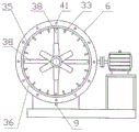
FIG. 1 is a schematic view of a geared gas purification apparatus;
FIG. 2 is a top view of the gear-driven gas purification apparatus of FIG. 1
FIG. 3 is a schematic top view of the internal structure of the gear-driven gas purification device;
FIG. 4 is a schematic view of a gear transmission configuration;
FIG. 5 is a cross-sectional view of a geared gas purification apparatus A-A;
FIG. 6 is a cross-sectional view of a gear driven gas purification apparatus B-B;
FIG. 7 is a cross-sectional view of a geared gas purification apparatus C-C;
FIG. 8 is a cross-sectional view of a geared gas purification apparatus D-D;
in the figure: 1 is a gear box body, 2 is a water mist box body, 3 is a water receiving box body, 4 is a gear box body access cover, 5 is a motor, 6 is a water mist box body flange, 7 is a gear box body flange, 8 is a water receiving box body flange, 9 is a water spray pipe connecting pipe, 10 is a water discharging hole, 11 is a bolt, 12 is a motor base, 13 is a main base, 14 is a screw, 15 is a sealing cover, 16 is a motor flange, 17 is a main transmission shaft, 18 is a bearing, 19 is a double-closing hollow supporting rod, 20 is a pinion shaft, 21 is a pinion gear, 22 is a rotating shaft gear, 23 is a main transmission gear, 24 is a gear box, 25 is a gear box front cover, 26 is a front rotating shaft, 27 is a rear rotating shaft, 28 is a water receiving box shaft, 29 is a water mist box shaft, 30 is a shaft connecting flange, 31 is a water receiving grid, 32 is a water receiving box water baffle, 33 is a mixing sheet, 34 is a water spray pipe, 35 is a water spray nozzle, 36 is a water mist box baffle, 37 is an umbrella cover, 38 is a fixed support rod, 39 is an impeller sheet group, 40 is a honeycomb grid, 41 is a bolt hole, and 42 is an overhaul screw plug.
Detailed Description
The gear transmission gas purification device of the utility model is realized in the way, and the following description is combined with the attached drawings for details.
See fig. 1-8, the utility model discloses gear drive gas purification device by: a gear transmission box body 1, a water mist box body 2, a water receiving box body 3, a gear box body repairing cover 4, a motor 5, a water mist box body flange 6, a gear box body flange 7, a water receiving box body flange 8, a water spray pipe connecting pipe 9, a water discharge hole 10, a bolt 11, a motor base 12, a main base 13, a screw 14, a sealing cover 15, a motor flange 16, a main transmission shaft 17, a bearing 18, a double-closing hollow supporting rod 19, an auxiliary gear shaft 20, an auxiliary gear 21, a rotating shaft gear 22, a main transmission gear 23, a gear box 24, a gear box front cover 25, a front rotating shaft 26, a rear rotating shaft 27, a water receiving box shaft 28, a water mist box shaft 29, a shaft receiving flange 30, a water receiving grid 31, a water receiving box water baffle 32, a mixed flow sheet 33, a water spray pipe 34, a water spray nozzle 35, a water mist box water baffle 36, an umbrella-shaped cover 37, a fixed supporting rod 38, an impeller sheet group 39, a honeycomb grid, the method is characterized in that: the gear transmission gas purification device consists of a gear transmission box body 1, a water mist box body 2 and a water receiving box body 3; the method comprises the following steps: the gear transmission device, the spray atomization exhaust facility and the water-gas separation exhaust facility realize the functions of purification, fire prevention and oil fume exhaust, and the purified waste oil and sludge are beneficial to centralized recovery processing, comprehensive utilization is realized, the environment-friendly function is improved, and energy is saved.
Referring to fig. 1 and 2, a water mist box body 2 and a water collecting box body 3 are respectively arranged at the left side and the right side of a gear transmission box body 1, and the gear transmission box body 1 and the water mist box body 2 are fixedly connected through a gear box body flange 7, a water mist box body flange 6 and a bolt 11; the gear transmission box body 1 and the water collection box body 3 are fixedly connected through a gear box body flange 7, a water collection box body flange 8 and a bolt 11; the bottom of the gear transmission box body 1 is provided with a main base 13, and the motor 5 is fixedly connected with the main base 13 through a motor base 12 arranged on one side of the gear transmission box body 1.
Referring to fig. 1 to 4 and 6, the gear transmission device: the device consists of a gear transmission box body 1, a motor 5, a motor flange 16, a main transmission shaft 17, a main transmission gear 23, a rotating shaft gear 22, an auxiliary gear 21, a front rotating shaft 26, a rear rotating shaft 27, a shaft connecting flange 30, an auxiliary gear shaft 20, a gear box 24, a double-closing hollow support rod 19 and a fixed support rod 38; the gear box 24 is fixed in the middle of the gear transmission box body 1 through a group of double-combined hollow support rods 19 and a group of fixed support rods 38, the output shaft of the motor 5 is in transmission connection with one end of a main transmission shaft 17 through a motor flange 16, a main transmission gear 23 arranged on the main transmission shaft 17 is in meshing transmission connection with a rotating shaft gear 22 arranged on a front rotating shaft 26, and the rotating shaft gear 22 is in meshing transmission connection with an auxiliary gear 21 arranged on an auxiliary gear shaft 20 to drive the auxiliary gear shaft 20, the front rotating shaft 26 and a rear rotating shaft 27 to rotate; the front end of the front rotating shaft 26 is provided with a shaft connecting flange 30 for being in transmission connection with a water mist box shaft 29, and the rear end of the rear rotating shaft 27 is provided with a shaft connecting flange 30 for being in transmission connection with a water receiving box shaft 28, so that a gear transmission device is formed.
Referring to fig. 1, fig. 3 and fig. 5, the spray atomizing air exhausting facility: is prepared from the following components: the water mist box body 2, a water mist box body flange 6, a water mist box water baffle 36, a water spray pipe connecting pipe 9, a water spray pipe 34, a water spray nozzle 35, a mixed flow sheet 33, a fixed supporting rod 38, a bearing 18, a water mist box shaft 29, an impeller sheet group 39, an umbrella-shaped cover 37 and a shaft connecting flange 30; the water mist box body 2 is fixedly connected with a gear box body flange 7 of the gear transmission box body 1 through a water mist box body flange 6, a water mist box water baffle 36 is arranged at the inner edge of the water mist box body flange 6 at the front end part of the water mist box body 2, water spray nozzles 35 are uniformly distributed on a water spray pipe 34, and the lower end of the water spray pipe 34 penetrates through the water mist box body 2 to be connected with a water spray pipe connecting pipe 9; the flow mixing pieces 33 are uniformly arranged on the inner wall of the water mist box body 2, the water mist box shaft 29 is fixedly arranged between the two groups of fixed supporting rods 38 through the bearing 18, the water mist box shaft 29 is arranged in the water mist box body 2 through the fixed supporting rods 38, the front end of the water mist box shaft 29 is provided with an impeller piece group 39 and an umbrella-shaped cover 37, and the rear end of the water mist box shaft 29 is provided with a shaft connecting flange 30.
Starting a motor gear transmission device to work, simultaneously externally arranging a water pump to pump water, spraying water flow into the water mist box body 2 from a water spraying nozzle 35 through a water spraying pipe connecting pipe 9 and a water spraying pipe 34, simultaneously working a motor 5, driving a main transmission shaft 17 to be meshed through a main transmission gear 23, a rotation shaft gear 22 and an auxiliary gear 21 to drive a front rotation shaft 26, a rear rotation shaft 27 and an auxiliary gear shaft 20 to rotate, connecting the front rotation shaft 26 through a front end shaft connecting flange 30 to drive a water mist box shaft 29 to rotate, driving an impeller sheet group 39 in the water mist box body 2 to rotate, throwing and scattering the water flow sprayed by the water spraying nozzle 35 through the impeller sheet group 39 and colliding with the inner wall of the water mist box body 2 to form water mist, simultaneously sucking smoke gas from the front end of the water mist box body 2, mutually contacting and mixing the sucked smoke gas and the scattered water mist of the blades to form a dirty water mist body, mixed flow is discharged into the gear transmission box body 1 through the mixed flow plate group 33 and discharged through the water collection box body 3.
See fig. 1, fig. 3, fig. 7, fig. 8, water-air separation exhaust facility: is prepared from the following components: the water receiving tank comprises a water receiving tank body 3, a water receiving tank body flange 8, a water receiving tank water baffle 32, a water discharging hole 10, a honeycomb grid 40, a water receiving grid 31, a fixed supporting rod 38, a bearing 18, a water receiving tank shaft 28, an impeller sheet group 39 and a shaft connecting flange 30; the water receiving box body 3 is fixedly connected with a gear box body flange 7 of the gear transmission box body 1 through a water receiving box body flange 8, a water receiving box baffle 32 is arranged at the inner edge of the water receiving box body flange 8 at the rear end of the water receiving box body 3, the honeycomb grids 40 and the water receiving grids 31 are arranged in the water receiving box body 3, the water receiving grids 31 are uniformly distributed along the circumference of the inner wall of the water receiving box body 3, and the bottom of the water receiving box body 3 is provided with a water drainage hole 10; the water receiving tank shaft 28 is arranged in the water receiving tank body 3 and is fixedly arranged between the two groups of fixed supporting rods 38 through a bearing 18, the water receiving tank shaft 28 is arranged in the water receiving tank body 3 through the fixed supporting rods 38, the front end of the water receiving tank shaft 28 is provided with a shaft connecting flange 30, and the rear end of the water receiving tank shaft 28 is provided with an impeller blade group 39.
The working principle is as follows:
the utility model discloses gear drive gas purification device during operation:
the gear-driven gas purification device is powered on and started, a water pump is arranged outside, the water pump is connected with a water spray pipe 34 through a water spray pipe connecting pipe 9, water flow is sprayed into the water mist box body 2 through a water spray nozzle 35, meanwhile, the motor 5 is powered on and works, an output shaft of the motor 5 is in transmission connection with a main transmission shaft 17, a front rotating shaft 26, a rear rotating shaft 27 and an auxiliary gear shaft 20 are driven to rotate through the meshing of a main transmission gear 23, a rotating shaft gear 22 and an auxiliary gear 21, the front rotating shaft 26 is connected with a shaft connecting flange 30 at the front end to drive a water mist box shaft 29 to rotate and drive an impeller sheet set 39 in the water mist box body 2 to rotate, the water flow sprayed by the water spray nozzle 35 is thrown and scattered through blades of the impeller sheet set 39 and collides with the inner wall of the water mist box body 2 to form water mist, meanwhile, smoke gas is sucked by the front end of the, the rotary discharge is backward, and then the mixed flow is discharged into the gear transmission box body 1 through the mixed flow plate group 33; the muddy water mixture is discharged backward into the water receiving tank body 3 through the gear box 24 inside the gear transmission tank body 1 and the gear transmission tank body 1.
The rotating shaft gear 22 in the gear transmission box body 1 drives the rear rotating shaft 27 and the water receiving box shaft 28 to rotate, the impeller blade set 39 is driven to rotate, the dirty mixed water body discharged through the water mist box body 2 and the gear transmission box body 1 is continuously discharged backwards, the dirty water body is in collision contact through the water receiving grid 31, the dirty mixed water body is separated from gas and purified, then the honeycomb grid 40 is used for noise reduction and separation of the dirty water body and the gas, and the purified gas is discharged through the rear end of the water receiving box body 3. The dirty water body recovered in the water collection tank body 3 flows out through the drain hole 10 and is discharged to an external purification oil separation water tank through an external connecting pipeline, oil water, dust and water body of the dirty water body are separated, precipitated and purified, and the purified water is sent to a water spray pipe 34 of a water spray pipe connecting pipe 9 on the water spray tank body 2 through an external water pump and a water spray pipe nozzle 35 to be sprayed and recycled, so that the energy-saving, environment-friendly and purification effect is achieved.
The utility model provides a traditional electrostatic purification equipment power consumption big, waste oil mud is difficult for retrieving, the fire prevention effect is poor, the problem of conflagration takes place easily, through spraying the combined action of purification, because exhaust air-purifying, be close to the room temperature relatively, can also add the ventilation air with the air-purifying emission that is fit for, mend the wind as work, the use of air conditioner has been reduced, increase the fire prevention function, concentrate waste oil and mud and retrieve, improve water cyclic utilization, the energy can be saved, save the fund, the equipment function has been increased, the environmental protection equipment availability factor has been improved.
Claims (5)
1. A gear drive gas purification device is characterized in that: comprises a gear transmission box body (1), a water mist box body (2), a water receiving box body (3), a gear box body maintenance cover (4), a motor (5), a water mist box body flange (6), a gear box body flange (7), a water receiving box body flange (8), a water spraying pipe connecting pipe (9), a water discharging hole (10), a bolt (11), a motor base (12), a main base (13), a screw (14), a sealing cover (15), a motor flange plate (16), a main transmission shaft (17), a bearing (18), a double-closing hollow supporting rod (19), an auxiliary gear shaft (20), an auxiliary gear (21), a rotating shaft gear (22), a main transmission gear (23), a gear box (24), a gear box front cover (25), a front rotating shaft (26), a rear rotating shaft (27), a water receiving box shaft (28), a water mist box shaft (29), a shaft connecting flange plate (30), a water receiving grid (31), The water collecting tank water baffle (32), the mixed flow sheet (33), the spray pipe (34), the spray nozzle (35), the water fog tank water baffle (36), the umbrella-shaped cover (37), the fixed support rod (38), the impeller sheet group (39), the honeycomb grid (40), the bolt hole (41) and the maintenance screw plug (42) form, the gear transmission gas purifying device is composed of a gear transmission tank body (1), a water fog tank body (2) and a water collecting tank body (3); the method comprises the following steps: the gear transmission device, the spray atomization exhaust facility and the water-gas separation exhaust facility realize the functions of purification, fire prevention and oil smoke discharge.
2. The gear transmission gas purification device according to claim 1, wherein the water mist box body (2) and the water collection box body (3) are respectively arranged at the left side and the right side of the gear transmission box body (1), and the gear transmission box body (1) is fixedly connected with the water mist box body (2) through a gear box body flange (7), a water mist box body flange (6) and a bolt (11); the gear transmission box body (1) is fixedly connected with the water collection box body (3) through a gear box body flange (7), a water collection box body flange (8) and a bolt (11); a main base (13) is arranged at the bottom of the gear transmission box body (1), and the motor (5) is fixedly connected with the main base (13) through a motor base (12) arranged on one side of the gear transmission box body (1).
3. The geared gas purification apparatus of claim 1, wherein the geared apparatus: the gear box is composed of a main transmission shaft (17), a main transmission gear (23), a rotating shaft gear (22), an auxiliary gear (21), a front rotating shaft (26), a rear rotating shaft (27), a shaft connecting flange (30), an auxiliary gear shaft (20), a gear box (24), a double-combination hollow support rod (19) and a fixed support rod (38) which are arranged in a gear transmission box body (1), wherein the gear box (24) is fixed in the middle of the gear transmission box body (1) through a group of double-combination hollow support rods (19) and a group of fixed support rods (38), an output shaft of a motor (5) is in transmission connection with one end of the main transmission shaft (17) through a motor flange (16), the main transmission gear (23) arranged on the main transmission shaft (17) is in meshing transmission connection with the rotating shaft gear (22) arranged on the front rotating shaft (26), the rotating shaft gear (22) is in meshing transmission connection with the auxiliary gear (21) arranged on the auxiliary, the auxiliary gear shaft (20), the front rotating shaft (26) and the rear rotating shaft (27) are driven to rotate; the front end of the front rotating shaft (26) is provided with a shaft connecting flange plate (30) for being in transmission connection with a water mist box shaft (29), and the rear end of the rear rotating shaft (27) is provided with a shaft connecting flange plate (30) for being in transmission connection with a water receiving box shaft (28) to form a gear transmission device.
4. The gear-driven gas purification device according to claim 1, wherein the spray atomizing air exhausting means: is prepared from the following components: the water mist box comprises a water mist box body (2), water mist box body flanges (6), a water mist box water baffle plate (36), a water spray pipe connecting pipe (9), a water spray pipe (34), a water spray nozzle (35), a mixed flow sheet (33), a fixed supporting rod (38), a bearing (18), a water mist box shaft (29), an impeller sheet group (39), an umbrella-shaped cover (37) and a shaft connecting flange plate (30), wherein the water mist box body (2) is fixedly connected with a gear box body flange (7) of a gear transmission box body (1) through the water mist box body flange (6), the water mist box water baffle plate (36) is arranged at the inner edge of the water mist box body flange (6) at the front end part of the water mist box body (2), the water spray nozzles (35) are uniformly arranged on the water spray pipe (34), the lower ends of the water spray pipes (34) penetrate through the water mist box body (2) to be connected with the water spray pipe connecting pipe (9), the mixed flow sheets, the water mist box shaft (29) is fixedly arranged between the two groups of fixed supporting rods (38) through a bearing (18), the water mist box shaft (29) is arranged in the water mist box body (2) through the fixed supporting rods (38), an impeller blade group (39) and an umbrella-shaped cover (37) are arranged at the front end of the water mist box shaft (29), and a shaft connecting flange (30) is arranged at the rear end of the water mist box shaft (29).
5. The gear-driven gas purification device according to claim 1, wherein the water-air separation exhaust facility: is prepared from the following components: the water receiving box body (3), a water receiving box body flange (8), a water receiving box water baffle plate (32), a water discharging hole (10), a honeycomb grid (40), a water receiving grid (31), a fixed supporting rod (38), a bearing (18), a water receiving box shaft (28), an impeller blade group (39) and a shaft connecting flange plate (30); the water collection box body (3) is fixedly connected with a gear box body flange (7) of the gear transmission box body (1) through a water collection box body flange (8), a water collection box water baffle plate (32) is arranged at the inner edge of the water collection box body flange (8) at the rear end of the water collection box body (3), the honeycomb grids (40) and the water collection grids (31) are arranged in the water collection box body (3), the water collection grids (31) are uniformly distributed along the circumference of the inner wall of the water collection box body (3), and drain holes (10) are formed in the bottom of the water collection box body (3); the water receiving tank shaft (28) is arranged in the water receiving tank body (3) and is fixedly arranged between the two groups of fixed supporting rods (38) through a bearing (18), the water receiving tank shaft (28) is arranged in the water receiving tank body (3) through the fixed supporting rods (38), the front end of the water receiving tank shaft (28) is provided with a shaft connecting flange plate (30), and the rear end of the water receiving tank shaft is provided with an impeller plate group (39).
Priority Applications (1)
| Application Number | Priority Date | Filing Date | Title |
|---|---|---|---|
| CN202020022550.4U CN211612069U (en) | 2020-01-07 | 2020-01-07 | Gear drive gas purification device |
Applications Claiming Priority (1)
| Application Number | Priority Date | Filing Date | Title |
|---|---|---|---|
| CN202020022550.4U CN211612069U (en) | 2020-01-07 | 2020-01-07 | Gear drive gas purification device |
Publications (1)
| Publication Number | Publication Date |
|---|---|
| CN211612069U true CN211612069U (en) | 2020-10-02 |
Family
ID=72636095
Family Applications (1)
| Application Number | Title | Priority Date | Filing Date |
|---|---|---|---|
| CN202020022550.4U Expired - Fee Related CN211612069U (en) | 2020-01-07 | 2020-01-07 | Gear drive gas purification device |
Country Status (1)
| Country | Link |
|---|---|
| CN (1) | CN211612069U (en) |
-
2020
- 2020-01-07 CN CN202020022550.4U patent/CN211612069U/en not_active Expired - Fee Related
Similar Documents
| Publication | Publication Date | Title |
|---|---|---|
| CN206715590U (en) | One kind building removal construction dust arrester | |
| CN212119443U (en) | Spray tower device for efficiently removing water mist | |
| CN211612069U (en) | Gear drive gas purification device | |
| CN103816759A (en) | Coaxial integrated multilayered centrifugal washing gas-clearing machine | |
| CN111921310A (en) | Environmental protection dust collecting equipment of building engineering construction | |
| CN112275075A (en) | Fountain exhaust treatment device | |
| CN211913151U (en) | Chain transmission gas purification device | |
| CN108905463B (en) | Furniture production air pollution processing apparatus | |
| CN211913153U (en) | Belt transmission gas purification device | |
| CN111054166A (en) | Gear drive gas purification device | |
| CN215654536U (en) | Environment-friendly dust removal equipment | |
| CN203507725U (en) | Air purifying device based on water cyclone device | |
| CN214345230U (en) | Flue gas desulfurization dusting tower | |
| CN112833439B (en) | Oil smoke purifies all-in-one | |
| CN112833412A (en) | Environment-friendly flue gas purification equipment for waste incineration | |
| CN211585795U (en) | Spraying device for smoke purification | |
| CN112588783A (en) | Intelligent waste recovery device for environmental art design | |
| CN208989765U (en) | A kind of tuberculosis prevention and treatment Atomerizing disinfecting apparatus | |
| CN112774380A (en) | Flue gas sprays dust fall odour removal device | |
| CN110586310A (en) | Dustless reducing mechanism of building material | |
| CN220939960U (en) | Peculiar smell control purifier | |
| CN212017188U (en) | Gas purification device | |
| CN212618550U (en) | High-efficient environment-friendly fortune water petticoat pipe | |
| CN218741028U (en) | Waste gas dust removal purification system | |
| CN213790715U (en) | Air purification equipment for construction site |
Legal Events
| Date | Code | Title | Description |
|---|---|---|---|
| GR01 | Patent grant | ||
| GR01 | Patent grant | ||
| CF01 | Termination of patent right due to non-payment of annual fee |
Granted publication date: 20201002 |
|
| CF01 | Termination of patent right due to non-payment of annual fee |