CN211597733U - Building templates link for civil engineering - Google Patents
Building templates link for civil engineering Download PDFInfo
- Publication number
- CN211597733U CN211597733U CN202020031838.8U CN202020031838U CN211597733U CN 211597733 U CN211597733 U CN 211597733U CN 202020031838 U CN202020031838 U CN 202020031838U CN 211597733 U CN211597733 U CN 211597733U
- Authority
- CN
- China
- Prior art keywords
- frame
- civil engineering
- bolt
- rod
- shaft
- Prior art date
- Legal status (The legal status is an assumption and is not a legal conclusion. Google has not performed a legal analysis and makes no representation as to the accuracy of the status listed.)
- Expired - Fee Related
Links
- 230000003014 reinforcing effect Effects 0.000 claims abstract description 9
- 238000009434 installation Methods 0.000 claims description 13
- 238000009415 formwork Methods 0.000 claims description 8
- 238000005728 strengthening Methods 0.000 claims description 4
- 230000000712 assembly Effects 0.000 abstract 1
- 238000000429 assembly Methods 0.000 abstract 1
- 238000004806 packaging method and process Methods 0.000 description 3
- 230000001012 protector Effects 0.000 description 3
- 230000002787 reinforcement Effects 0.000 description 2
- 238000003466 welding Methods 0.000 description 2
- 230000009286 beneficial effect Effects 0.000 description 1
- NJPPVKZQTLUDBO-UHFFFAOYSA-N novaluron Chemical compound C1=C(Cl)C(OC(F)(F)C(OC(F)(F)F)F)=CC=C1NC(=O)NC(=O)C1=C(F)C=CC=C1F NJPPVKZQTLUDBO-UHFFFAOYSA-N 0.000 description 1
Images


Landscapes
- Forms Removed On Construction Sites Or Auxiliary Members Thereof (AREA)
Abstract
The utility model discloses a building templates link for civil engineering belongs to the civil engineering field. The building template connecting frame for civil engineering comprises a fixing frame, supporting frames and a cross frame, wherein two groups of supporting assemblies are mounted on the outer side of the cross frame through bolts, the supporting frames are mounted at two ends of the cross frame through mounting shafts, reinforcing frames are mounted on the outer side of the top of the supporting frames through mounting shafts, the fixing frame is mounted on the top of the outer side of each reinforcing frame through bolts, threaded rods are mounted at the bottoms of the supporting frames through inner bolts, and a chassis is mounted at the bottoms of the threaded rods through bolts; the utility model discloses an install support frame adjustable device's overall height, make it can highly carry out height-adjusting according to building templates for the device is applicable to the building templates of co-altitude not, has enlarged the application range value of device, has improved the practicality of device.
Description
Technical Field
The utility model relates to a civil engineering technical field especially relates to building templates link for civil engineering.
Background
The building template is a temporary supporting structure, which is manufactured according to the design requirements, so that a concrete structure and a member are formed according to the specified position and geometric dimension, the correct position of the concrete structure and the member is kept, the self weight of the building template and the external load acting on the building template are borne, and the purpose of template engineering is realized.
Through the retrieval, chinese patent application number is CN 208329620U's patent, discloses a building templates link for civil engineering, including fixed stay post, connection regulator, roll adjustment board, splint fixer and protector, the both ends are inlayed about the fixed stay post and are had connection regulator, the inboard roll adjustment board of connecting the regulator connection, roll adjustment board downside is equipped with the splint fixer, splint fixer inboard is equipped with protector, protector passes through the bolt fastening on the roll adjustment board, and a building templates link for civil engineering in the above-mentioned patent exists following not enoughly:
1. the device does not adjust the overall height of the device according to the height of the building template, so that the device cannot be suitable for building templates with different heights, the application range value of the device is reduced, and the practicability of the device is reduced;
2. the device can not carry out adjusting device's whole width according to the width of building templates for the device has certain limitation when using, and be not convenient for use.
SUMMERY OF THE UTILITY MODEL
The utility model aims at solving the problem that the whole height and the whole width of the adjusting device are not convenient to carry out according to the concrete specification of the building template in the prior art, and the building template link for civil engineering that proposes.
In order to achieve the above purpose, the utility model adopts the following technical scheme:
building templates link for civil engineering, including mount, support frame and crossbearer, two sets of supporting component are installed through the bolt in the outside of crossbearer, the support frame is installed through the installation axle in the both ends of crossbearer, the reinforcement frame is installed through the installation axle in the support frame top outside, the mount is installed through the bolt in the outside top of reinforcement frame, the threaded rod is installed through interior bolt in the bottom of support frame, the chassis is installed through the bolt in the bottom of threaded rod.
Preferably, install the fixed axle in the supporting component, the bracing piece is installed through the pintle in the bottom of fixed axle, and the extension rod is installed through the locating pin in the bottom of bracing piece, and the axle bed is installed through the pintle in the bottom of extension rod.
Preferably, a supporting plate is installed in the fixing frame, an adjusting rod is installed on the front face of the supporting plate through a shaft bracket, and a fixing piece is installed at the bottom of the adjusting rod through a shaft bolt.
Preferably, install the arc in the installation axle, the connecting piece is installed through the bolt in the top of arc, and the top welding of connecting piece has the axle spare.
Preferably, a connecting rod is installed in the reinforcing frame, loop bars are installed at two ends of the connecting rod through locating bolts, and a connecting shaft is installed at one end of each loop bar through a bolt.
Preferably, a threaded shaft rod is installed in the support frame, and a shaft sleeve is movably installed at the top of the threaded shaft rod through a rotating shaft.
Compared with the prior art, the utility model provides a building templates link for civil engineering possesses following beneficial effect:
1. this building templates link for civil engineering installs the support frame through the top at the threaded rod, through support frame adjustable device's overall height, makes it can carry out height-adjusting according to building templates's height for the device is applicable to not co-altitude building templates, has enlarged the application range value of device, has improved the practicality of device.
2. This building templates link for civil engineering installs the loop bar through the both ends at the connecting rod, through the horizontal length of the multiplicable connecting rod of loop bar to can carry out adjusting device's whole width according to building templates's width, increase the application range of device, increase the controllability of device, improve the flexibility of device, the device of being convenient for uses.
3. This building templates link for civil engineering installs two sets of supporting component through the bottom at the crossbearer, through the bearing structure of the multiplicable device of supporting component, has improved the fastness that the device supported, prevents that building templates from taking place not hard up phenomenon, has guaranteed the fastness that building templates connects, has improved the practicality of device.
The part that does not relate to among the device all is the same with prior art or can adopt prior art to realize, the utility model discloses can carry out adjusting device's whole width and whole height according to building templates's specification, make its applicable building templates in different specifications, enlarge the application range value of device, improve the practicality of device.
Drawings
Fig. 1 is a schematic view of the overall structure of a building formwork connecting frame for civil engineering of the present invention;
fig. 2 is a schematic structural view of the fixing frame of the building formwork connecting frame for civil engineering of the present invention;
fig. 3 is a schematic structural view of the mounting shaft of the building template connecting frame for civil engineering of the utility model;
fig. 4 is a schematic structural view of the reinforcing frame of the building formwork connecting frame for civil engineering of the present invention;
fig. 5 is the utility model provides a building templates link support frame for civil engineering's structural schematic.
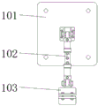
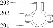
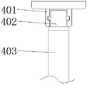
In the figure: 1. a fixed mount; 101. a support plate; 102. adjusting a rod; 103. a fixing member; 2. installing a shaft; 201. an arcuate member; 202. a connecting member; 203. a shaft member; 3. a reinforcing frame; 301. a connecting rod; 302. a loop bar; 303. a connecting shaft; 4. a support frame; 401. a shaft sleeve; 402. a rotating shaft; 403. a threaded shaft; 5. a cross frame; 6. a support assembly; 601. a fixed shaft; 602. a support bar; 603. an extension rod; 604. a shaft seat; 7. a threaded rod; 701. a chassis.
Detailed Description
The technical solutions in the embodiments of the present invention will be described clearly and completely with reference to the accompanying drawings in the embodiments of the present invention, and it is obvious that the described embodiments are only some embodiments of the present invention, not all embodiments.
In the description of the present invention, it is to be understood that the terms "upper", "lower", "front", "rear", "left", "right", "top", "bottom", "inner", "outer", and the like indicate orientations or positional relationships based on the orientations or positional relationships shown in the drawings, and are only for convenience of description and simplicity of description, and do not indicate or imply that the device or element being referred to must have a particular orientation, be constructed and operated in a particular orientation, and therefore, should not be construed as limiting the present invention.
Referring to fig. 1-5, the building template connecting frame for civil engineering comprises a fixed frame 1, supporting frames 4 and a cross frame 5, wherein two groups of supporting components 6 are arranged at the outer side of the cross frame 5 through bolts, the cross frame 5 can increase the firmness of the connection of the two groups of supporting frames 4, the stability of the device is improved, the supporting structure of the device can be increased through the supporting components 6, the firmness of the device support is improved, the building template is prevented from loosening, the firmness of the connection of the building template is ensured, the practicability of the device is improved, the supporting frames 4 are arranged at the two ends of the cross frame 5 through an installation shaft 2, the device can be conveniently assembled through the installation shaft 2, the assembly efficiency of the device is improved, the overall height of the device can be adjusted according to the height of the building template through the matching of the supporting frames 4 and a threaded rod 7, so that the device can be, the application range value of the device is enlarged, the practicability of the device is improved, reinforcing frames 3 are installed on the outer sides of the tops of the support frames 4 through installation shafts 2, the reinforcing frames 3 can further increase the firmness of connection of the two sets of support frames 4, the firmness of the device is ensured, fixing frames 1 are installed on the outer sides of the reinforcing frames 3 through bolts, the fixing frames 1 can support building templates, the firmness of installation of the building templates is ensured, threaded rods 7 are installed on the bottoms of the support frames 4 through inner bolts, the threaded rods 7 can be matched with the support frames 4 to increase the overall height of the device, the device is convenient to adjust in height, chassis 701 is installed on the bottoms of the threaded rods 7 through bolts, the contact surface between the chassis 701 and the ground can be increased, slippage of the threaded rods 7 is prevented, and the installation stability of.
Further, install fixed axle 601 in the supporting component 6, the bracing piece 602 angle regulation of bracing piece can be convenient for to fixed axle 601, bracing piece 602 is installed through the pintle in the bottom of fixed axle 601, the front of bracing piece 602 is equipped with the pilot pin, extension rod 603 position can be fixed through the pilot pin, the extension rod 603 of being convenient for adjusts length, extension rod 603 is installed through the pilot pin in the bottom of bracing piece 602, through the whole length of extension rod 603 multiplicable bracing piece 602, be convenient for adjust as required according to supporting, the controllability of device has been increased, the flexibility of device has been improved, axle bed 604 is installed through the pintle in the bottom of extension rod 603, the contact surface of axle bed 604 multiplicable extension rod 603 and ground, the steadiness that extension rod 603 supported has been improved.
Further, install backup pad 101 in mount 1, backup pad 101 multiplicable and building templates's contact surface, the steadiness that building templates connected has been improved, the front of backup pad 101 is installed through the pedestal and is adjusted pole 102, adjust pole 102 can be convenient for adjust the whole length of mount 1 as required according to the support, the adjustability of device has been increased, the bottom of adjusting pole 102 is installed mounting 103 through the pintle, mounting 103 can be convenient for fix adjusting pole 102 at the outside top of strengthening frame 3, the device of being convenient for is installed, the installation effectiveness of device has been improved.
Further, install arc 201 in installation axle 2, arc 201 can be fixed in the outside of support frame 4 through bolt and connecting piece 202 cooperation, the device of being convenient for assembles, device packaging efficiency is improved, the device of being convenient for carries out the dismouting, connecting piece 202 is installed through the bolt at the top of arc 201, connecting piece 202 can be assembled with the device of being convenient for of arc 201 cooperation, the top welding of connecting piece 202 has axle 203, axle 203 can cooperate with connecting axle 303, the strengthening frame 3 of being convenient for assembles, device packaging efficiency has been improved.
Further, install connecting rod 301 in the strengthening frame 3, the loop bar 302 of can being convenient for in the inside of connecting rod 301 extendible to loop bar 302 is installed, loop bar 302 is installed through the pilot pin at the both ends of connecting rod 301, horizontal length through loop bar 302 multiplicable connecting rod 301, thereby can carry out adjusting device's whole width according to building templates's width, increase the application range of device, the controllability of device has been increased, the flexibility of device has been improved, the device of being convenient for uses, connecting axle 303 is installed through the bolt to the one end of loop bar 302, connecting axle 303 can be convenient for loop bar 302 and install the inside shaft member 203 of axle 2 and be connected, the loop bar 302 of being convenient for is installed, the device packaging efficiency has been improved.
Further, install screw shaft pole 403 in the support frame 4, can with the screw-thread fit in the threaded rod 7 outside through rotatory screw shaft pole 403, the screw shaft pole 403 rebound of being convenient for to the whole height of multiplicable device, the device of being convenient for carries out the regulation of height, and axle sleeve 401 is installed through pivot 402 movable mounting in the top of screw shaft pole 403, and the screw shaft pole 403 of being convenient for can be convenient for with the cooperation of axle sleeve 401 to rotate, the screw shaft pole 403 pivoted flexibility of being convenient for.
In the utility model, the screw thread shaft lever 403 can be matched with the screw thread outside the screw thread 7 by rotating, so that the screw thread shaft lever 403 can move upwards conveniently, thereby increasing the overall height of the device, facilitating the height adjustment of the device, leading the device to adjust the height according to the height of the building template, leading the device to be applicable to the building templates with different heights, expanding the use range value of the device, improving the practicability of the device, increasing the horizontal length of the connecting rod 301 by the loop bar 302, further leading the overall width of the device to be adjusted according to the width of the building template, increasing the use range of the device, increasing the adjustability of the device, improving the flexibility of the device, facilitating the use of the device, increasing the supporting structure of the device by the supporting component 6, improving the supporting firmness of the device, preventing the building template from loosening, and ensuring the firmness of the connection of the building template, the practicability of the device is improved.
The above, only be the concrete implementation of the preferred embodiment of the present invention, but the protection scope of the present invention is not limited thereto, and any person skilled in the art is in the technical scope of the present invention, according to the technical solution of the present invention and the utility model, the concept of which is equivalent to replace or change, should be covered within the protection scope of the present invention.
Claims (6)
1. Building templates link for civil engineering, including mount (1), support frame (4) and crossbearer (5), its characterized in that, two sets of supporting component (6) are installed through the bolt in the outside of crossbearer (5), support frame (4) are installed through installation axle (2) at the both ends of crossbearer (5), strengthen frame (3) are installed through installation axle (2) in the support frame (4) top outside, install mount (1) through the bolt in the outside top of strengthening frame (3), threaded rod (7) are installed through interior bolt in the bottom of support frame (4), chassis (701) are installed through the bolt in the bottom of threaded rod (7).
2. The building formwork connecting frame for civil engineering as defined in claim 1, characterized in that fixed axle (601) is installed in the supporting component (6), the bottom of fixed axle (601) is installed with supporting rod (602) through the axle bolt, the bottom of supporting rod (602) is installed with extending rod (603) through the positioning bolt, the bottom of extending rod (603) is installed with axle seat (604) through the axle bolt.
3. The building formwork connecting frame for civil engineering as defined in claim 1, characterized in that, the supporting plate (101) is installed in the fixed mount (1), the adjusting rod (102) is installed on the front of the supporting plate (101) through the shaft bracket, the fixing member (103) is installed on the bottom of the adjusting rod (102) through the shaft bolt.
4. The building formwork connecting frame for civil engineering according to claim 1, characterized in that an arc member (201) is installed in the installation shaft (2), a connecting member (202) is installed on the top of the arc member (201) through a bolt, and a shaft member (203) is welded on the top of the connecting member (202).
5. The building formwork connecting frame for civil engineering as defined in claim 4, wherein the reinforcing frame (3) is installed with a connecting rod (301), both ends of the connecting rod (301) are installed with a loop bar (302) through a positioning bolt, and one end of the loop bar (302) is installed with a connecting shaft (303) through a bolt.
6. The building formwork connecting frame for civil engineering as defined in claim 1, wherein threaded shaft rod (403) is installed in the support frame (4), and bushing (401) is movably installed on top of threaded shaft rod (403) through rotating shaft (402).
Priority Applications (1)
| Application Number | Priority Date | Filing Date | Title |
|---|---|---|---|
| CN202020031838.8U CN211597733U (en) | 2020-01-08 | 2020-01-08 | Building templates link for civil engineering |
Applications Claiming Priority (1)
| Application Number | Priority Date | Filing Date | Title |
|---|---|---|---|
| CN202020031838.8U CN211597733U (en) | 2020-01-08 | 2020-01-08 | Building templates link for civil engineering |
Publications (1)
| Publication Number | Publication Date |
|---|---|
| CN211597733U true CN211597733U (en) | 2020-09-29 |
Family
ID=72600924
Family Applications (1)
| Application Number | Title | Priority Date | Filing Date |
|---|---|---|---|
| CN202020031838.8U Expired - Fee Related CN211597733U (en) | 2020-01-08 | 2020-01-08 | Building templates link for civil engineering |
Country Status (1)
| Country | Link |
|---|---|
| CN (1) | CN211597733U (en) |
Cited By (2)
| Publication number | Priority date | Publication date | Assignee | Title |
|---|---|---|---|---|
| CN112252706A (en) * | 2020-10-09 | 2021-01-22 | 史润涛 | Method for installing residential formwork for building engineering construction |
| CN112681739A (en) * | 2021-01-28 | 2021-04-20 | 陕西建工第六建设集团有限公司 | Tool type positioning steel plate |
-
2020
- 2020-01-08 CN CN202020031838.8U patent/CN211597733U/en not_active Expired - Fee Related
Cited By (2)
| Publication number | Priority date | Publication date | Assignee | Title |
|---|---|---|---|---|
| CN112252706A (en) * | 2020-10-09 | 2021-01-22 | 史润涛 | Method for installing residential formwork for building engineering construction |
| CN112681739A (en) * | 2021-01-28 | 2021-04-20 | 陕西建工第六建设集团有限公司 | Tool type positioning steel plate |
Similar Documents
| Publication | Publication Date | Title |
|---|---|---|
| CN211597733U (en) | Building templates link for civil engineering | |
| CN213572923U (en) | Portable stair scaffold | |
| CN210587810U (en) | Automobile chassis welding support frame | |
| CN210508192U (en) | Floor support convenient to fixed calandria | |
| CN216516112U (en) | Safe steel structure node component | |
| CN217028233U (en) | Assembly type structure's reinforcement connection structure | |
| CN218941011U (en) | Photovoltaic support | |
| CN219432235U (en) | Device for fastening accessories of photovoltaic bracket | |
| CN220210340U (en) | Diagonal bracing for photovoltaic fixing support | |
| CN219414205U (en) | Adjustable metal fixing support for electromechanical equipment | |
| CN212927339U (en) | Anti-tilting device for supporting building template | |
| CN219999280U (en) | Photovoltaic bracket | |
| CN217537806U (en) | Adjustable bracketing is used to girder steel scaffold frame | |
| CN109339553A (en) | It is a kind of to build firm electric power tower device | |
| CN219329721U (en) | Connection structure of photovoltaic support and pile body | |
| CN219227500U (en) | Upright post lifting mechanism of flexible photovoltaic bracket | |
| CN217010757U (en) | Photovoltaic supporting structure | |
| CN219011941U (en) | Stair pouring formwork supporting structure | |
| CN219473329U (en) | Assembled rack for lithium battery production equipment | |
| CN220521558U (en) | Spliced light steel keel with limiting structure | |
| CN219029629U (en) | Adjustable cushion part mounting structure for bicycle | |
| CN210739740U (en) | Simple adjustable support mounting seat | |
| CN213115456U (en) | Machine position supporting member based on climbing frame | |
| CN220036702U (en) | Tunnel supporting device with auxiliary support | |
| CN219298831U (en) | Positioning device convenient to adjust and used for installing inclined column steel structure |
Legal Events
| Date | Code | Title | Description |
|---|---|---|---|
| GR01 | Patent grant | ||
| GR01 | Patent grant | ||
| CF01 | Termination of patent right due to non-payment of annual fee | ||
| CF01 | Termination of patent right due to non-payment of annual fee |
Granted publication date: 20200929 |