CN219298831U - Positioning device convenient to adjust and used for installing inclined column steel structure - Google Patents
Positioning device convenient to adjust and used for installing inclined column steel structure Download PDFInfo
- Publication number
- CN219298831U CN219298831U CN202320297198.9U CN202320297198U CN219298831U CN 219298831 U CN219298831 U CN 219298831U CN 202320297198 U CN202320297198 U CN 202320297198U CN 219298831 U CN219298831 U CN 219298831U
- Authority
- CN
- China
- Prior art keywords
- plate
- rod
- moving
- steel structure
- positioning device
- Prior art date
- Legal status (The legal status is an assumption and is not a legal conclusion. Google has not performed a legal analysis and makes no representation as to the accuracy of the status listed.)
- Active
Links
- 229910000831 Steel Inorganic materials 0.000 title claims abstract description 36
- 239000010959 steel Substances 0.000 title claims abstract description 36
- 238000013016 damping Methods 0.000 claims description 3
- 238000009434 installation Methods 0.000 abstract description 11
- 238000010276 construction Methods 0.000 abstract description 5
- 230000004048 modification Effects 0.000 description 2
- 238000012986 modification Methods 0.000 description 2
- 230000009286 beneficial effect Effects 0.000 description 1
- 238000010586 diagram Methods 0.000 description 1
- 238000004519 manufacturing process Methods 0.000 description 1
- 239000000463 material Substances 0.000 description 1
- 238000003466 welding Methods 0.000 description 1
Images


Classifications
-
- Y—GENERAL TAGGING OF NEW TECHNOLOGICAL DEVELOPMENTS; GENERAL TAGGING OF CROSS-SECTIONAL TECHNOLOGIES SPANNING OVER SEVERAL SECTIONS OF THE IPC; TECHNICAL SUBJECTS COVERED BY FORMER USPC CROSS-REFERENCE ART COLLECTIONS [XRACs] AND DIGESTS
- Y02—TECHNOLOGIES OR APPLICATIONS FOR MITIGATION OR ADAPTATION AGAINST CLIMATE CHANGE
- Y02E—REDUCTION OF GREENHOUSE GAS [GHG] EMISSIONS, RELATED TO ENERGY GENERATION, TRANSMISSION OR DISTRIBUTION
- Y02E10/00—Energy generation through renewable energy sources
- Y02E10/50—Photovoltaic [PV] energy
Landscapes
- Conveying And Assembling Of Building Elements In Situ (AREA)
Abstract
The utility model discloses a positioning device for installing a diagonal column steel structure, which is convenient to adjust, and comprises a bottom plate and a bearing plate, wherein a supporting rod is arranged at the upper end of the bottom plate, the bearing plate is arranged at the top end of the supporting rod, the supporting rods are arranged in a staggered manner, connecting grooves are formed in the rear ends of the bearing plate and the bottom plate, connecting plates are arranged in the connecting grooves in a clamping manner, a fixed rod penetrates through the connecting plates, a motor is arranged at the outer end of the bearing plate, the top end of the motor is connected with a threaded rod, a moving block is connected with the outer end of the threaded rod in a threaded manner, a moving plate is connected with the right end of the moving block, the moving plate penetrates through the fixed plate and a limiting plate, the lower end of the moving plate is arranged at the output end of the telescopic plate, and a jig frame is arranged above the moving plate. This positioner is used in installation of batter post steel construction convenient to adjust is convenient for adjust the height of bed-jig, and the bed-jig of the different size types of being convenient for change, convenient to use.
Description
Technical Field
The utility model relates to the technical field of steel structure installation, in particular to a positioning device convenient to adjust for installing a diagonal column steel structure.
Background
The steel structure is a structure formed by steel materials, is one of main building structure types, and is known from the patent of the utility model with the authority of the publication number CN114856212U, the inclined column steel structure is generally initially fixed by means of a jig frame, while the patent of the utility model with the authority of the publication number CN214144792U discloses an adjustable jig frame for manufacturing a complex curved surface steel structure, through the arrangement of lifting plates, fixing seats and jig frame seats, jig frame seats with different heights and angles are installed according to different adjustment of the inclination angle of the curved surface steel structure to be placed, the adjustable jig frame is installed on the surface of the fixing seats through positioning rods, and the electric push rod can push the fixing seats to lift, so that the height of the placed steel structure can be quickly adjusted, meanwhile, the hydraulic cylinder can be controlled to work to uniformly adjust the height of the top of a main board, and the adjustable jig frame is convenient to use and can adapt to the placement and use of the steel structures with different curved surface degrees.
The existing diagonal column steel structure installation positioning device is usually in a fixed mode, the height of a jig frame is inconvenient to adjust, the jigs of different specifications are inconvenient to replace, and the device is not suitable for installation and use of steel structures of different sizes and types, so that the positioning device for the diagonal column steel structure installation is convenient to adjust, and the problem in the prior art is solved conveniently.
Disclosure of Invention
The utility model aims to provide a positioning device for installing a diagonal column steel structure, which is convenient to adjust, and aims to solve the problems that most of the diagonal column steel structure installing positioning devices proposed in the background art are usually in a fixed mode, are inconvenient to adjust the height of a jig frame, are inconvenient to replace jigs with different specifications and are not suitable for installing and using steel structures with different sizes.
In order to achieve the above purpose, the present utility model provides the following technical solutions: positioning device is used in installation of batter post steel construction convenient to adjust, including bottom plate and bed-jig:
the upper end of the bottom plate is provided with a supporting rod, the top end of the supporting rod is provided with a bearing plate, the supporting rods are arranged in a staggered mode, the rear ends of the bearing plate and the bottom plate are provided with connecting grooves, connecting plates are arranged in the connecting grooves in a clamping mode, and fixing rods penetrate through the connecting plates;
the motor is arranged at the outer end of the bearing plate, the top end of the motor is connected with a threaded rod, the outer end of the threaded rod is in threaded connection with a moving block, the right end of the moving block is connected with a moving plate, the moving plate penetrates through the fixed plate and the limiting plate, the lower end of the moving plate is arranged at the output end of the telescopic plate, and the telescopic plate is arranged inside the fixed plate and the limiting plate;
the inside of movable plate has been seted up the through-hole, the top of movable plate is equipped with the bed-jig, the bottom of bed-jig runs through the movable plate through the installation pole, the inside restriction pole that runs through of installation pole, both ends all are connected with the regulation pole through damping rotation about the restriction pole.
Preferably, the connecting plate is arranged at the front ends of the bearing plate and the bottom plate, and the connecting plate corresponds to the connecting groove in size and position.
Preferably, the moving plate and the bearing plate form a lifting structure.
Preferably, the adjusting rod is connected with the limiting rod to form a 'shape' structure.
Preferably, the side view longitudinal sections of the fixing plate and the limiting plate are of inverted U-shaped structures.
Preferably, the mounting rod and the moving plate form a dismounting structure.
Compared with the prior art, the utility model has the beneficial effects that: the positioning device for installing the inclined column steel structure is convenient to adjust, is convenient for adjusting the height of the jig frame, is convenient for replacing the jig frames with different sizes and types, and is convenient to use;
1. the lifting structure is formed by the moving plate and the bearing plate, the left end and the right end of the moving plate penetrate through the fixed plate and the limiting plate, the lower end of the moving plate is arranged on the telescopic plate, the height of the jig frame can be conveniently and quickly adjusted, and different heights can be controlled according to actual needs so as to install the inclined column steel structure;
2. the jig frame is provided with a mounting rod, a limiting rod and an adjusting rod, the limiting rod penetrates through the mounting rod inside the mounting rod on the moving plate through the mounting rod, the adjusting rod is connected with the limiting rod to form a 'shape' structure, the jig frame with different sizes and types can be conveniently mounted and replaced, and the inclined column steel structures with different specifications can be conveniently mounted and positioned.
Drawings
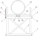
FIG. 1 is a schematic elevational view of the present utility model;
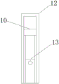
FIG. 2 is a schematic side view in cross-section of the present utility model;
FIG. 3 is a schematic side view of a limiting plate of the present utility model;
fig. 4 is a schematic diagram of a moving plate structure according to the present utility model.
In the figure: 1. a bottom plate; 2. a support rod; 3. a carrying plate; 4. a connecting groove; 5. a connecting plate; 6. a fixed rod; 7. a motor; 8. a threaded rod; 9. a moving block; 10. a moving plate; 11. a fixing plate; 12. a limiting plate; 13. a telescoping plate; 14. a jig frame; 15. a mounting rod; 16. a limiting rod; 17. and (5) adjusting the rod.
Detailed Description
The technical solutions of the embodiments of the present utility model will be clearly and completely described below with reference to the accompanying drawings in the embodiments of the present utility model, and it is apparent that the described embodiments are only some embodiments of the present utility model, but not all embodiments, and all other embodiments obtained by those skilled in the art without making creative efforts based on the embodiments of the present utility model are included in the protection scope of the present utility model.
Referring to fig. 1-4, the present utility model provides a technical solution: the utility model provides a positioning device is used in installation of batter post steel construction convenient to adjust, including bottom plate 1, bracing piece 2, loading board 3, spread groove 4, connecting plate 5, dead lever 6, motor 7, threaded rod 8, movable block 9, movable plate 10, fixed plate 11, limiting plate 12, expansion plate 13, bed-jig 14, installation pole 15, limiting rod 16 and regulation pole 17, the batter post steel construction is usually used bed-jig 14 to install the location, as shown in fig. 1 and fig. 2, connect through bracing piece 2 between bottom plate 1 and the loading board 3, the top of loading board 3 is equipped with bed-jig 14, be convenient for install the location steel construction;
as shown in fig. 2, the rear ends of the bearing plate 3 and the bottom plate 1 are provided with connecting grooves 4, and connecting plates 5 are arranged at the front ends of the bearing plate 3 and the bottom plate 1, when the lengths of the bearing plate 3 and the bottom plate 1 need to be lengthened, the connecting plates 5 and the connecting grooves 4 can be used for clamping connection, and then fixing rods 6 penetrate through the connecting plates 5, so that the lengthened bearing plates 3 are stably connected, and the subsequent steel structure installation is convenient;
as shown in fig. 1, a motor 7 is installed at the outer end of the bearing plate 3, the motor 7 is connected with a threaded rod 8, a moving block 9 is connected with the outer end of the threaded rod 8 in a threaded manner, the moving block 9 is fixedly connected with a moving plate 10, the moving plate 10 penetrates through a fixed plate 11 and a limiting plate 12, a telescopic plate 13 is installed inside the fixed plate 11 and the limiting plate 12, the lower end of the moving plate 10 is installed at the output end of the telescopic plate 13, when the height of a jig frame 14 needs to be adjusted, the motor 7 is started, the moving plate 10 moves up and down above the bearing plate 3, and after the jig frame 14 moves to a required height position, the telescopic plate 13 is fixed;
according to the requirements of the inclined column steel structure, a plurality of moving plates 10 can be arranged on the bearing plate 3 at the same time, the jig frame 14 is adjusted to different height positions according to actual conditions, as shown in fig. 2, thereby being convenient for installing and positioning the inclined column steel structure, as shown in fig. 4, through holes are formed in the moving plate 10, the bottom end of the jig frame 14 penetrates through the moving plate 10 through an installing rod 15, a limiting rod 16 penetrates through the inside of the installing rod 15, the left end and the right end of the limiting rod 16 are connected with adjusting rods 17 through damping rotation, when the jig frames 14 with different sizes are required to be replaced, the adjusting rods 17 can be rotated, the limiting rods 16 are pulled out of the jig frames 14, then the installing rods 15 are pulled out of the moving plate 10, so that the jig frames 14 are detached, and then the jig frame 14 is reinstalled, so that a series of operations of the positioning device for installing the inclined column steel structure convenient to adjust can be completed.
Standard parts used in the utility model can be purchased from the market, special-shaped parts can be customized according to the description of the specification and the drawings, the specific connection modes of all parts adopt conventional means such as mature bolts, rivets and welding in the prior art, the machinery, the parts and the equipment adopt conventional modes in the prior art, and the circuit connection adopts conventional connection modes in the prior art, so that details are not described in detail in the specification, and the utility model belongs to the prior art known to the person skilled in the art.
Although the present utility model has been described with reference to the foregoing embodiments, it will be apparent to those skilled in the art that modifications may be made to the embodiments described, or equivalents may be substituted for elements thereof, and any modifications, equivalents, improvements and changes may be made without departing from the spirit and principles of the present utility model.
Claims (6)
1. Positioning device for installing inclined column steel structure convenient to adjust, comprising a bottom plate (1) and a jig frame (14), and being characterized in that:
the support device is characterized in that a support rod (2) is arranged at the upper end of the bottom plate (1), a bearing plate (3) is arranged at the top end of the support rod (2), the support rods (2) are arranged in a staggered mode, connecting grooves (4) are formed in the rear ends of the bearing plate (3) and the bottom plate (1), a connecting plate (5) is arranged in the connecting grooves (4) in a clamping mode, and a fixing rod (6) penetrates through the connecting plate (5);
the motor (7) is installed at the outer end of the bearing plate (3), a threaded rod (8) is connected to the top end of the motor (7), a moving block (9) is connected to the outer end of the threaded rod (8) in a threaded mode, a moving plate (10) is connected to the right end of the moving block (9), the moving plate (10) penetrates through a fixed plate (11) and a limiting plate (12), the lower end of the moving plate (10) is installed at the output end of a telescopic plate (13), and the telescopic plate (13) is installed inside the fixed plate (11) and the limiting plate (12);
through holes are formed in the moving plate (10), a jig frame (14) is arranged above the moving plate (10), the bottom end of the jig frame (14) penetrates through the moving plate (10) through a mounting rod (15), a limiting rod (16) penetrates through the mounting rod (15), and adjusting rods (17) are connected to the left end and the right end of the limiting rod (16) through damping rotation.
2. The positioning device for installing a diagonal column steel structure convenient to adjust according to claim 1, wherein: the connecting plate (5) is arranged at the front ends of the bearing plate (3) and the bottom plate (1), and the connecting plate (5) corresponds to the connecting groove (4) in size and position.
3. The positioning device for installing a diagonal column steel structure convenient to adjust according to claim 1, wherein: the moving plate (10) and the bearing plate (3) form a lifting structure.
4. The positioning device for installing a diagonal column steel structure convenient to adjust according to claim 1, wherein: the adjusting rod (17) is connected with the limiting rod (16) to form a ']' structure.
5. The positioning device for installing a diagonal column steel structure convenient to adjust according to claim 1, wherein: the side view longitudinal sections of the fixing plate (11) and the limiting plate (12) are of inverted U-shaped structures.
6. The positioning device for installing a diagonal column steel structure convenient to adjust according to claim 1, wherein: the mounting rod (15) and the moving plate (10) form a dismounting structure.
Priority Applications (1)
| Application Number | Priority Date | Filing Date | Title |
|---|---|---|---|
| CN202320297198.9U CN219298831U (en) | 2023-02-23 | 2023-02-23 | Positioning device convenient to adjust and used for installing inclined column steel structure |
Applications Claiming Priority (1)
| Application Number | Priority Date | Filing Date | Title |
|---|---|---|---|
| CN202320297198.9U CN219298831U (en) | 2023-02-23 | 2023-02-23 | Positioning device convenient to adjust and used for installing inclined column steel structure |
Publications (1)
| Publication Number | Publication Date |
|---|---|
| CN219298831U true CN219298831U (en) | 2023-07-04 |
Family
ID=86987829
Family Applications (1)
| Application Number | Title | Priority Date | Filing Date |
|---|---|---|---|
| CN202320297198.9U Active CN219298831U (en) | 2023-02-23 | 2023-02-23 | Positioning device convenient to adjust and used for installing inclined column steel structure |
Country Status (1)
| Country | Link |
|---|---|
| CN (1) | CN219298831U (en) |
-
2023
- 2023-02-23 CN CN202320297198.9U patent/CN219298831U/en active Active
Similar Documents
| Publication | Publication Date | Title |
|---|---|---|
| CN117344991A (en) | A type of steel structure rapid positioning device and installation technology | |
| CN223241083U (en) | Adjustable Bailey support frame | |
| CN220556714U (en) | But reuse's roofing photovoltaic mounting bracket | |
| CN216921499U (en) | Top bracing device for controlling crack of super-long reinforced concrete structure | |
| CN212198273U (en) | Portable tower footing wall-attached frame inner support | |
| CN111745175B (en) | Pipeline perforating device convenient for adjusting hole distance | |
| CN217537806U (en) | Adjustable bracketing is used to girder steel scaffold frame | |
| CN221399733U (en) | Tunnel construction support | |
| CN219794722U (en) | Steel beam connection auxiliary frame | |
| CN220057656U (en) | Bridge supports adjusting device | |
| CN222771906U (en) | Installation and positioning tool | |
| CN223358107U (en) | A bracket for bridge construction | |
| CN220705036U (en) | Civil air defense door frame perpendicularity regulator | |
| CN220791263U (en) | Auxiliary installation device for tunnel primary support arch frame | |
| CN219327266U (en) | Dry hanging large plate mounting seat with adjustable positioning position | |
| CN221218783U (en) | Wind-powered electricity generation foundation construction anchor slab installation adjusting device | |
| CN220889494U (en) | Building support template fixed knot constructs | |
| CN222374113U (en) | A concrete prefabricated component hanging frame assembly | |
| CN222227320U (en) | A temporary fixing device for concrete support of open excavation foundation pit | |
| CN221354195U (en) | Flexible support device for roof | |
| CN221988023U (en) | A tower crane attachment structure | |
| CN220645856U (en) | Frame base type emulsion drilling machine fixing support | |
| CN219999262U (en) | Various steel tile roof photovoltaic power plant mounting structure | |
| CN220173630U (en) | Novel adjustable cabinet base for data center | |
| CN221399597U (en) | Steel reinforcement cage strutting arrangement |
Legal Events
| Date | Code | Title | Description |
|---|---|---|---|
| GR01 | Patent grant | ||
| GR01 | Patent grant |