CN211519248U - Fuel tank fixing device and fuel tank assembly - Google Patents
Fuel tank fixing device and fuel tank assembly Download PDFInfo
- Publication number
- CN211519248U CN211519248U CN202020063075.5U CN202020063075U CN211519248U CN 211519248 U CN211519248 U CN 211519248U CN 202020063075 U CN202020063075 U CN 202020063075U CN 211519248 U CN211519248 U CN 211519248U
- Authority
- CN
- China
- Prior art keywords
- fuel tank
- strap
- bracket
- fixing device
- frame
- Prior art date
- Legal status (The legal status is an assumption and is not a legal conclusion. Google has not performed a legal analysis and makes no representation as to the accuracy of the status listed.)
- Withdrawn - After Issue
Links
- 239000002828 fuel tank Substances 0.000 title claims abstract description 132
- 230000007704 transition Effects 0.000 claims description 23
- 238000009434 installation Methods 0.000 claims description 10
- 125000006850 spacer group Chemical group 0.000 claims description 7
- 229910000838 Al alloy Inorganic materials 0.000 claims description 3
- 230000002787 reinforcement Effects 0.000 claims 1
- 230000000694 effects Effects 0.000 abstract description 9
- 238000003466 welding Methods 0.000 description 4
- 230000003014 reinforcing effect Effects 0.000 description 3
- 238000005452 bending Methods 0.000 description 2
- 239000000446 fuel Substances 0.000 description 2
- 239000000295 fuel oil Substances 0.000 description 2
- 238000012423 maintenance Methods 0.000 description 2
- 238000004519 manufacturing process Methods 0.000 description 2
- 208000037656 Respiratory Sounds Diseases 0.000 description 1
- 238000005266 casting Methods 0.000 description 1
- 238000010030 laminating Methods 0.000 description 1
- 230000000149 penetrating effect Effects 0.000 description 1
- 230000008707 rearrangement Effects 0.000 description 1
- 238000006467 substitution reaction Methods 0.000 description 1
Images


Landscapes
- Cooling, Air Intake And Gas Exhaust, And Fuel Tank Arrangements In Propulsion Units (AREA)
Abstract
The utility model relates to an automobile parts technical field discloses a fuel tank fixing device and fuel tank assembly. This fuel tank fixing device includes strap subassembly and bracket, strap subassembly is including being first strap and the second strap that the contained angle set up, first strap is connected in the second strap through first connecting piece, the cross-section of bracket is L shape structure, the frame that the bracket can connect the car through the second connecting piece, the both ends of bracket are connected respectively in the free end of first strap and the free end of second strap, bracket and strap subassembly can enclose to establish and form the frame shape structure that is used for holding the fuel tank, the surface of fuel tank can laminate in the internal surface of frame shape structure. The utility model provides a fuel tank fixing device because first strap is connected in the second strap through first connecting piece for the equal atress in both ends of first strap and second strap, thereby make first strap and second strap can laminate in the surface of fuel tank well, improve fixed effect.
Description
Technical Field
The utility model relates to an automobile parts technical field especially relates to a fuel tank fixing device and fuel tank assembly.
Background
Along with the development of domestic long-distance transportation, the volume requirement of a whole vehicle on a fuel tank is continuously increased, however, the larger the volume of the fuel tank is, the larger the impact force of fuel oil is when the whole vehicle brakes suddenly and starts suddenly.
The fuel tank fixing device in the prior art generally comprises a bracket and a strap, wherein the bracket is connected to a frame of an automobile through a transition support, the bracket is welded to the transition support, the transition support is connected to the frame of the automobile through a fixing bolt, under the influence of the impact force of fuel oil, the phenomenon that a welding line between the bracket and the transition support is easy to crack is caused, the bracket and the strap are loosened, the fuel tank moves due to the loosening of the bracket and the strap, the fixing bolt connected with the frame of the transition support is further caused to lose efficacy, and the maintenance cost of a user is increased. In addition, current bracket and strap formula structure as an organic whole usually, both are L shape structure, and the both ends of strap are connected respectively to the both ends of bracket, when connecting, because two free ends atress of strap lead to the edge of strap can not be fine laminating in the surface of fuel tank, influence fixed effect.
SUMMERY OF THE UTILITY MODEL
Based on above, an object of the utility model is to provide a fuel tank fixing device and fuel tank assembly, welding crackle can not appear in the bracket, and the strap can be better laminated in the surface of fuel tank, improves the fixed effect to the fuel tank.
In order to achieve the purpose, the utility model adopts the following technical proposal:
a fuel tank securing device comprising:
the clamp belt assembly comprises a first clamp belt and a second clamp belt which are arranged at an included angle, and the first clamp belt is connected to the second clamp belt through a first connecting piece;
the bracket, its cross-section is L shape structure, the frame that the bracket can connect the car through the second connecting piece, the both ends of bracket connect respectively in the free end of first strap with the free end of second strap, the bracket with the strap subassembly can enclose to establish and form the frame shape structure that is used for holding the fuel tank, the surface of fuel tank can laminate in the internal surface of frame shape structure.
As a preferred scheme of the fuel tank fixing device, the fuel tank fixing device further comprises an anti-skid gasket, and the anti-skid gasket is arranged between the frame-shaped structure and the fuel tank.
As a preferable scheme of the fuel tank fixing device, a plurality of anti-skid protrusions are arranged on one side, close to the fuel tank, of the anti-skid liner.
As a preferable aspect of the fuel tank fixing device, the anti-slip gasket includes:
the first gasket is of an L-shaped structure, a first installation groove is formed in one side, away from the fuel tank, of the first gasket, and the bracket is arranged in the first installation groove;
and one side, far away from the fuel tank, of the second gasket is provided with a second mounting groove, and the first clamp band and the second clamp band correspond to the two second gaskets and are respectively positioned in the corresponding mounting grooves.
As a preferable scheme of the fuel tank fixing device, one side of the bracket, which is far away from the fuel tank, is provided with a transitional cushion block, and the transitional cushion block is used for adjusting the distance between the bracket and the frame.
As a preferred scheme of the fuel tank fixing device, the transition cushion block is made of aluminum alloy, and lightening holes are formed in the transition cushion block.
Preferably, the bracket is provided with a reinforcing plate on one side close to the fuel tank.
As a preferred scheme of the fuel tank fixing device, the first strap is provided with a connecting hole, the second strap is provided with a through hole, and the first connecting piece can sequentially penetrate through the through hole and the connecting hole.
In order to achieve the above object, the utility model also provides a fuel tank assembly, including the fuel tank, still include as above arbitrary scheme fuel tank fixing device, the fuel tank passes through fuel tank fixing device is fixed in on the frame of car.
Preferably, the fuel tank fixing devices are arranged in a plurality of numbers, and the fuel tank fixing devices are arranged at intervals along the length direction of the fuel tank.
The utility model has the advantages that:
the utility model provides a fuel tank fixing device, this fuel tank fixing device includes bracket and strap subassembly, and the strap subassembly is including being the first strap and the second strap that the contained angle set up, when the both ends of bracket are connected with the free end of first strap and the free end of second strap respectively, because first strap is connected in the second strap through first connecting piece for the both ends of first strap and second strap are all atress, thereby make first strap and second strap can laminate in the surface of fuel tank well, improve fixed effect; the bracket is connected on the frame of car through the second connecting piece, compares with bracket among the prior art and transition scaffold weldment's mode, and joint strength is high, can not appear welding crack, and the reliability is high.
The utility model provides a fuel tank assembly, including foretell fuel tank fixing device, fixed effect is better, and the reliability is higher.
Drawings
In order to more clearly illustrate the technical solutions in the embodiments of the present invention, the drawings required to be used in the description of the embodiments of the present invention will be briefly described below, and it is obvious that the drawings in the following description are only some embodiments of the present invention, and for those skilled in the art, other drawings can be obtained according to the contents of the embodiments of the present invention and the drawings without creative efforts.
FIG. 1 is an exploded schematic view of a fuel tank assembly provided by the present invention;
FIG. 2 is a schematic structural view of a band assembly of the fuel tank fixing device according to the present invention;
FIG. 3 is an enlarged view of a portion of FIG. 2 at A;
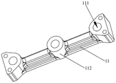
FIG. 4 is a schematic structural view of a bracket of a fuel tank securing device according to the present invention;
FIG. 5 is an enlarged view of a portion of FIG. 4 at B;
FIG. 6 is a schematic structural view of a transition pad of a fuel tank securing assembly according to the present invention positioned at the front of a vehicle frame;
FIG. 7 is a schematic structural view of a transition pad of a fuel tank securing device located in the middle of a vehicle frame according to the present invention;
FIG. 8 is a schematic structural view of a transition pad of a fuel tank securing assembly provided at the rear of a vehicle frame;
FIG. 9 is a schematic view of a first gasket of a fuel tank securement device in accordance with the present invention;
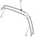
FIG. 10 is a schematic view of a second gasket of the fuel tank fixing device of the present invention
In the figure:
100-a fuel tank;
1-a bracket; 11-a transition pad block; 111-assembly holes; 112-a boss; 12-a fourth mounting hole;
2-a cuff assembly; 21-a first band; 211-a first cylindrical pin; 22-a second band; 221-a second cylindrical pin; 23-a first connector; 24-a first connection plate; 241-a first mounting hole; 242-a bushing; 25-a second connecting plate;
3-anti-slip liner; 31-a first gasket; 311-a first mounting groove; 32-a second liner; 321-second mounting groove.
Detailed Description
The present invention will be described in further detail with reference to the accompanying drawings and examples. It is to be understood that the specific embodiments described herein are merely illustrative of the invention and are not limiting of the invention. It should be further noted that, for the convenience of description, only some of the structures related to the present invention are shown in the drawings, not all of the structures.
In the description of the present invention, unless expressly stated or limited otherwise, the terms "connected," "connected," and "fixed" are to be construed broadly, e.g., as meaning permanently connected, detachably connected, or integral to one another; can be mechanically or electrically connected; either directly or indirectly through intervening media, either internally or in any other relationship. The specific meaning of the above terms in the present invention can be understood in specific cases to those skilled in the art.
In the present disclosure, unless expressly stated or limited otherwise, the first feature "on" or "under" the second feature may comprise direct contact between the first and second features, or may comprise contact between the first and second features not directly. Also, the first feature being "on," "above" and "over" the second feature includes the first feature being directly on and obliquely above the second feature, or merely indicating that the first feature is at a higher level than the second feature. A first feature being "under," "below," and "beneath" a second feature includes the first feature being directly under and obliquely below the second feature, or simply meaning that the first feature is at a lesser elevation than the second feature.
In the description of the present embodiment, the terms "upper", "lower", "left", "right", and the like are used in the orientation or positional relationship shown in the drawings only for convenience of description and simplicity of operation, and do not indicate or imply that the device or element referred to must have a specific orientation, be constructed in a specific orientation, and be operated, and thus should not be construed as limiting the present invention. Furthermore, the terms "first" and "second" are used only for descriptive purposes and are not intended to have a special meaning.
As shown in fig. 1, the present embodiment provides a fuel tank assembly including a fuel tank 100 and a fuel tank fixing device, wherein the fuel tank 100 is fixed to a frame of an automobile by the fuel tank fixing device.
In this embodiment, the number of the fuel tank fixing devices is plural, the plural fuel tank fixing devices are arranged at intervals along the length direction of the fuel tank 100, and the plural fuel tank fixing devices fix the fuel tank 100 at the same time, so that the fixing effect on the fuel tank 100 can be improved, and the stability of the fuel tank 100 can be increased. In this embodiment, as shown in fig. 1, the number of the fuel tank fixing devices in the fuel tank assembly provided by this embodiment is three, and the three fuel tank fixing devices are uniformly and alternately arranged along the length direction of the fuel tank 100, so that the fuel tank 100 can be well fixed, and the manufacturing cost can be saved.
Specifically, in this embodiment, the fuel tank fixing device includes bracket 1 and strap assembly 2, wherein strap assembly 2 includes first strap 21 and second strap 22 that are the contained angle setting, first strap 21 passes through first connecting piece 23 and connects to second strap 22, the cross-section of bracket 1 is the L shape structure, bracket 1 can connect the frame of car through the second connecting piece, the both ends of bracket 1 are connected respectively in the free end of first strap 21 and the free end of second strap 22, bracket 1 and strap assembly 2 can enclose and establish the frame shape structure that is used for holding fuel tank 100, the surface of fuel tank 100 can laminate in the internal surface of frame shape structure.
When the two ends of the bracket 1 are respectively connected with the free end of the first strap 21 and the free end of the second strap 22, the first strap 21 is connected with the second strap 22 through the first connecting piece 23, so that the two ends of the first strap 21 and the second strap 22 are stressed, the first strap 21 and the second strap 22 can be well attached to the outer surface of the fuel tank 100, and the fixing effect is improved; bracket 1 is connected on the frame of car through the second connecting piece, compares with bracket 1 among the prior art and transition scaffold weldment's mode, and joint strength is high, can not appear welding crack, and the reliability is high.
Preferably, in this embodiment, the bracket 1 is formed by integral stamping and has a bending structure, and the bending radian is the same as that of the outer periphery of the fuel tank 100, so that the contact area between the bracket 1 and the outer periphery of the fuel tank 100 is increased, and the fixing effect is good.
Further, the fuel tank fixing device further comprises an anti-slip liner 3, the anti-slip liner 3 is arranged between the frame-shaped structure and the fuel tank 100, and a plurality of anti-slip protrusions are further arranged on one side, close to the fuel tank 100, of the anti-slip liner 3 and used for increasing friction force between the bracket 1 and the fuel tank 100 and between the belt assembly 2 and the fuel tank 100 and preventing the fuel tank 100 from shifting.
Preferably, the anti-skid pad 3 is made of rubber, so that the anti-skid effect is good, and the manufacturing cost is low.
Further, as shown in fig. 2, the first strap 21 is provided with a connecting hole, the second strap 22 is provided with a first through hole, and the first connecting member 23 can sequentially penetrate through the first through hole and the connecting hole, so as to connect the first strap 21 and the second strap 22.
Specifically, as shown in fig. 2, a first cylindrical pin 211 is disposed on the first band 21, a second cylindrical pin 221 is disposed on the second band 22, a connecting hole is disposed in a middle portion of the first cylindrical pin 211, a through hole is disposed in a middle portion of the second cylindrical pin 221, the first connecting member 23 is specifically a first bolt, the connecting hole is specifically a threaded hole, and the first bolt is threaded to the first cylindrical pin 211 after passing through the through hole of the second cylindrical pin 221. The bolt connection has the advantages of simple processing and convenient operation, and the distance between the first strap 21 and the second strap 22 can be adjusted by adjusting the length of the first bolt extending into the connecting hole on the first cylindrical pin 211, so that the first strap 21 and the second strap 22 can be well attached to the outer surface of the fuel tank 100.
Further, in order to achieve stable connection between the bracket 1 and the band assembly 2, as shown in fig. 2 to 5, a first connecting plate 24 is further disposed at an end of the first band 21 away from the second band 22, a first mounting hole 241 is disposed on the first connecting plate 24, a third mounting hole is disposed on the bracket 1 corresponding to the first mounting hole 241, and a third connecting member is sequentially inserted into the first mounting hole 241 and the third mounting hole to achieve fixed connection between the bracket 1 and the first band 21. Similarly, a second connecting plate 25 is further arranged at one end of the second strap 22, which is far away from the first strap 21, a second mounting hole is arranged on the second connecting plate 25, a fourth mounting hole 12 is arranged at a position, corresponding to the second mounting hole, on the bracket 1, and a fourth connecting piece is sequentially arranged in the second mounting hole and the fourth mounting hole 12 in a penetrating manner, so that the bracket 1 and the second strap 22 are fixedly connected.
Preferably, the first mounting hole 241 and the second mounting hole are further provided with a bushing 242, which can improve the wear resistance of the first mounting hole 241 and the second mounting hole and prolong the service life of the first connecting plate 24 and the second connecting plate 25.
Preferably, the first connecting plate 24 is welded to the first band 21, and the second connecting plate 25 is welded to the second band 22, so that the connection stability is good.
Further, as shown in fig. 4, a side of the bracket 1 away from the fuel tank 100 is provided with a transition pad 11, and the transition pad 11 is used for adjusting the distance between the bracket 1 and the vehicle frame. Specifically, the thickness of the transitional spacers 11 on the multiple fuel tank fixtures mounted on the fuel tank 100 can be adjusted according to the actual situation, so that the fuel tank fixtures can be well fixed on the frame. Preferably, the transition pad 11 is formed by casting.
Preferably, the transition pad 11 is made of aluminum alloy, and the transition pad 11 is provided with lightening holes. By adopting the mode, the fuel tank fixing device can achieve the index of reducing the weight by 10 percent, and when the weight of the whole automobile of the automobile is reduced by 10 percent, the fuel efficiency can be improved by 6 to 8 percent.
Further, the cross section of the bracket 1 is of a structure like a Chinese character 'ji', and a reinforcing plate is arranged on one side of the bracket 1 close to the fuel tank 100 to improve the strength of the bracket 1. In this embodiment, still weld on the reinforcing plate and have a plurality of nuts, the second connecting piece passes frame and transition cushion 11 and threaded connection in the nut in proper order, and the second connecting piece specifically is the second bolt, and joint strength is higher. Preferably, the number of nuts is three.
Specifically, in order to adapt to the specific structure of the vehicle frame, in the present embodiment, as shown in fig. 1 and fig. 6 to 8, the overall thickness of the transitional spacers 11 of the three fuel tank fixing devices increases from the front of the vehicle frame to the rear of the vehicle frame, and the transitional spacers 11 of the fuel tank fixing devices located at the front of the vehicle frame are of a flat plate structure, and three assembling holes 111 corresponding to the nuts are formed in the flat plate structure. The transition cushion block 11 of the fuel tank fixing device positioned in the middle of the frame is provided with three bosses 112 at positions corresponding to the nuts, and the three bosses 112 are provided with corresponding assembling holes 111. It is understood that the transitional spacer 11 of the fuel tank fixing device at the rear of the vehicle frame has the same structure as the transitional spacer 11 of the fuel tank fixing device at the middle of the vehicle frame, and the difference is only the difference of the height dimension of the boss 112, which is not described in detail herein.
Of course, in other embodiments, the transition piece 11 may be provided in other forms, as long as the function of adjusting the distance between the fuel tank fixing device and the fuel tank 100 can be achieved, and is not limited herein.
Further, as shown in fig. 9 to 10, the anti-slip liner 3 includes a first liner 31 and two second liners 32, the first liner 31 has an L-shaped structure, a first installation groove 311 is provided on a side of the first liner 31 away from the fuel tank 100, the bracket 1 is disposed in the first installation groove 311, a second installation groove 321 is provided on a side of the second liner 32 away from the fuel tank 100, and the first band 21 and the second band 22 respectively correspond to the two second liners 32 and are respectively located in the corresponding installation grooves 321. By providing the first mounting groove 311 and the second mounting groove 321, the bracket 1, the first band 21, and the second band 22 can be accurately positioned, and the bracket 1, the first band 21, and the second band 22 can be prevented from moving.
The fuel tank assembly that this embodiment provided, the lightweight of fuel tank assembly can be realized to strong, the maintenance is convenient, improves the dynamic of car, reduces fuel consumption, reduces exhaust pollution.
It should be noted that the foregoing is only a preferred embodiment of the present invention and the technical principles applied. It will be understood by those skilled in the art that the present invention is not limited to the particular embodiments described herein, but is capable of various obvious changes, rearrangements and substitutions as will now become apparent to those skilled in the art without departing from the scope of the invention. Therefore, although the present invention has been described in greater detail with reference to the above embodiments, the present invention is not limited to the above embodiments, and may include other equivalent embodiments without departing from the scope of the present invention.
Claims (10)
1. A fuel tank securing device, comprising:
the clamp belt assembly (2) comprises a first clamp belt (21) and a second clamp belt (22) which are arranged at an included angle, and the first clamp belt (21) is connected to the second clamp belt (22) through a first connecting piece (23);
bracket (1), its cross-section is L shape structure, bracket (1) can connect the frame of car through the second connecting piece, the both ends of bracket (1) connect respectively in the free end of first strap (21) with the free end of second strap (22), bracket (1) with strap subassembly (2) can enclose to establish and form the frame shape structure that is used for holding fuel tank (100), the surface of fuel tank (100) can laminate in the internal surface of frame shape structure.
2. Fuel tank fixing device according to claim 1, characterized in that it further comprises an anti-slip gasket (3), said anti-slip gasket (3) being arranged between said frame-shaped structure and said fuel tank (100).
3. Fuel tank fixing device according to claim 2, characterized in that the side of the anti-slip liner (3) close to the fuel tank (100) is provided with a plurality of anti-slip protrusions.
4. Fuel tank fixing arrangement according to claim 2, characterized in that the anti-slip gasket (3) comprises:
the first gasket (31) is of an L-shaped structure, a first installation groove (311) is formed in one side, away from the fuel tank (100), of the first gasket (31), and the bracket (1) is arranged in the first installation groove (311);
the fuel tank (100) is provided with two second gaskets (32), one side, far away from the fuel tank (100), of each second gasket (32) is provided with a second installation groove (321), and the first band clamp (21) and the second band clamp (22) correspond to the two second gaskets (32) respectively and are located in the corresponding installation grooves (321) respectively.
5. Fuel tank fixing device according to claim 1, characterized in that the side of the bracket (1) remote from the fuel tank (100) is provided with a transitional spacer (11), which transitional spacer (11) is used to adjust the distance between the bracket (1) and the vehicle frame.
6. A fuel tank fixing device according to claim 5, characterized in that the transition piece (11) is made of an aluminum alloy, and the transition piece (11) is provided with lightening holes.
7. Fuel tank fixing device according to claim 1, characterized in that the bracket (1) is further provided with a reinforcement plate on the side close to the fuel tank (100).
8. Fuel tank fixing device according to claim 1, characterized in that the first strap (21) is provided with a connecting hole and the second strap (22) is provided with a through hole, the first connecting piece (23) being able to be inserted in the through hole and the connecting hole in sequence.
9. A fuel tank assembly comprising a fuel tank (100), characterized in that it further comprises a fuel tank fixing device according to any one of claims 1-8, by means of which the fuel tank (100) is fixed to the frame of a motor vehicle.
10. A fuel tank assembly according to claim 9, wherein said fuel tank fixing means is plural in number, and a plurality of said fuel tank fixing means are provided at intervals along a length direction of said fuel tank (100).
Priority Applications (1)
| Application Number | Priority Date | Filing Date | Title |
|---|---|---|---|
| CN202020063075.5U CN211519248U (en) | 2020-01-13 | 2020-01-13 | Fuel tank fixing device and fuel tank assembly |
Applications Claiming Priority (1)
| Application Number | Priority Date | Filing Date | Title |
|---|---|---|---|
| CN202020063075.5U CN211519248U (en) | 2020-01-13 | 2020-01-13 | Fuel tank fixing device and fuel tank assembly |
Publications (1)
| Publication Number | Publication Date |
|---|---|
| CN211519248U true CN211519248U (en) | 2020-09-18 |
Family
ID=72468915
Family Applications (1)
| Application Number | Title | Priority Date | Filing Date |
|---|---|---|---|
| CN202020063075.5U Withdrawn - After Issue CN211519248U (en) | 2020-01-13 | 2020-01-13 | Fuel tank fixing device and fuel tank assembly |
Country Status (1)
| Country | Link |
|---|---|
| CN (1) | CN211519248U (en) |
Cited By (2)
| Publication number | Priority date | Publication date | Assignee | Title |
|---|---|---|---|---|
| CN113415431A (en) * | 2021-07-30 | 2021-09-21 | 天津爱思达新材料科技有限公司 | Winding structure for auxiliary fuel tank of airplane |
| CN115352274A (en) * | 2022-08-19 | 2022-11-18 | 一汽解放汽车有限公司 | Pressing force adjusting method and device, computer equipment storage medium and product |
-
2020
- 2020-01-13 CN CN202020063075.5U patent/CN211519248U/en not_active Withdrawn - After Issue
Cited By (3)
| Publication number | Priority date | Publication date | Assignee | Title |
|---|---|---|---|---|
| CN113415431A (en) * | 2021-07-30 | 2021-09-21 | 天津爱思达新材料科技有限公司 | Winding structure for auxiliary fuel tank of airplane |
| CN113415431B (en) * | 2021-07-30 | 2023-12-29 | 天津爱思达新材料科技有限公司 | Ring winding structure of auxiliary fuel tank of airplane |
| CN115352274A (en) * | 2022-08-19 | 2022-11-18 | 一汽解放汽车有限公司 | Pressing force adjusting method and device, computer equipment storage medium and product |
Similar Documents
| Publication | Publication Date | Title |
|---|---|---|
| CN211519248U (en) | Fuel tank fixing device and fuel tank assembly | |
| CN100483792C (en) | Cell component of electric motorcar | |
| CN205273171U (en) | Oil tank bracket of commercial car | |
| CN109404455B (en) | FRP (fiber reinforced Plastic) blade spring and assembly thereof | |
| CA2572678A1 (en) | Low profile saddle mount | |
| CN101982330A (en) | Improved front support device of truck engine | |
| CN212148256U (en) | Drive axle slide plate seat | |
| CN213322671U (en) | Combined bracket and vehicle | |
| CN221541770U (en) | Spare tyre installs crossbeam and has its vehicle | |
| CN214296102U (en) | Steering column mounting structure | |
| CN220096146U (en) | Arrangement structure of rotational molding oil tank for loader | |
| CN215921870U (en) | Heavy truck and front suspension bracket thereof | |
| CN213920979U (en) | Novel reduce vibration noise's hand braking installing support structure | |
| CN213948115U (en) | Suspension support and vehicle | |
| CN115312955B (en) | Vertical storage battery frame assembly and vehicle | |
| CN210637145U (en) | Silencer mounting bracket structure | |
| CN219214925U (en) | Storage battery box and vehicle with same | |
| CN219077152U (en) | Storage battery tray and vehicle with same | |
| CN216974985U (en) | Catalyst converter fixed bolster | |
| CN216739825U (en) | Excavator handrail and excavator | |
| CN215436438U (en) | Oil tank mounting seat, bogie and rail vehicle | |
| CN221585086U (en) | Battery mounting bracket assembly and vehicle with same | |
| CN211995056U (en) | Automobile rear suspension mounting structure | |
| CN214578551U (en) | Novel shock absorber mounting bracket structure | |
| CN210239893U (en) | Oil-water separator and fuel filter installation assembly |
Legal Events
| Date | Code | Title | Description |
|---|---|---|---|
| GR01 | Patent grant | ||
| GR01 | Patent grant | ||
| AV01 | Patent right actively abandoned | ||
| AV01 | Patent right actively abandoned | ||
| AV01 | Patent right actively abandoned |
Granted publication date: 20200918 Effective date of abandoning: 20240913 |
|
| AV01 | Patent right actively abandoned |
Granted publication date: 20200918 Effective date of abandoning: 20240913 |