CN211385338U - Building engineering abandonment concrete breaker - Google Patents
Building engineering abandonment concrete breaker Download PDFInfo
- Publication number
- CN211385338U CN211385338U CN201921557616.3U CN201921557616U CN211385338U CN 211385338 U CN211385338 U CN 211385338U CN 201921557616 U CN201921557616 U CN 201921557616U CN 211385338 U CN211385338 U CN 211385338U
- Authority
- CN
- China
- Prior art keywords
- fixedly connected
- frame body
- inner cavity
- motor
- box
- Prior art date
- Legal status (The legal status is an assumption and is not a legal conclusion. Google has not performed a legal analysis and makes no representation as to the accuracy of the status listed.)
- Active
Links
Images


Abstract
The utility model discloses a building engineering abandonment concrete breaker, including the box, the both sides at box top all run through and are provided with the inlet pipe, and the front side of box top surface is opened and is equipped with first through-hole, the rear side fixedly connected with backup pad of box top surface, the first motor of fixed surface at backup pad top is connected with, the front side fixedly connected with carousel of first motor output, the inner chamber and the carousel of primary shaft bearing pass through bearing swing joint. The utility model discloses a set up third through-hole, storage water tank, air exhauster, first through-hole, connecting plate, first framework, second through-hole, broken section of thick bamboo, broken cylinder, second framework, second motor, connecting rod, dead lever, carousel and second motor and mutually support, solved when broken abandonment concrete, crushing effect is relatively poor, and in crushing process, the concrete can produce a large amount of dusts, if can not in time handle the dust, then can cause the problem of environmental serious pollution.
Description
Technical Field
The utility model relates to a building engineering technical field specifically is a building engineering abandonment concrete breaker.
Background
The construction waste refers to residue, waste soil, waste material, sludge and other wastes generated in the process of constructing, laying, dismantling and repairing various buildings, structures, pipe networks and the like by construction, construction units or individuals, and can cause serious environmental pollution if the construction waste is not properly treated.
And the proportion that abandonment concrete occupied among the building rubbish is very big, in order to protect the environment, need use breaker to carry out broken handle to abandonment concrete, breaker on the present market is when broken abandonment concrete, and crushing effect is relatively poor, and at crushing in-process, the concrete can produce a large amount of dusts, if can not in time handle the dust, then can cause the serious pollution of environment.
SUMMERY OF THE UTILITY MODEL
An object of the utility model is to provide a building engineering abandonment concrete breaker possesses the advantage of high-efficient breakage and processing dust, has solved when broken abandonment concrete, and crushing effect is relatively poor, and in crushing process, the concrete can produce a large amount of dusts, if can not in time handle the dust, then can cause the problem of serious environmental pollution.
In order to achieve the above object, the utility model provides a following technical scheme: a crushing device for waste concrete in building engineering comprises a box body, wherein inlet pipes are arranged on two sides of the top of the box body in a penetrating mode, a first through hole is formed in the front side of the surface of the top of the box body, a supporting plate is fixedly connected to the rear side of the surface of the top of the box body, a first motor is fixedly connected to the surface of the top of the supporting plate, a rotary disc is fixedly connected to the front side of the output end of the first motor, a first bearing seat is fixedly connected to the rear side of the surface of the top of the box body and located on the front side of the supporting plate, an inner cavity of the first bearing seat is movably connected with the rotary disc through a bearing, a fixed rod is fixedly connected to the bottom of the front surface of the rotary disc, a connecting plate is sleeved on the front side of the surface of the fixed rod, a crushing barrel penetrates through the bottom of the connecting plate and is fixedly, the box comprises a box body, a first frame body, a second frame body, a crushing roller, a third through hole, a first guide plate, a discharging pipe, an air outlet pipe, an air inlet pipe, an air outlet pipe, a water storage tank, a water inlet pipe, a water outlet pipe, a water inlet pipe, a water outlet pipe, a water tank and a water tank, wherein the center of the inner cavity of the box body is positioned at the center of the right surface of the box body and is fixedly connected with the bottom of the air outlet pipe, the bottom of the air outlet pipe penetrates through the inner cavity of the water storage tank, the right side of the top of the water storage tank penetrates through the water inlet pipe, and the right side of the bottom of the inner cavity of the water storage tank penetrates through the water outlet pipe.
Preferably, the connection mode of the connection position of the connecting plate and the fixing rod is fixed connection, and the bottom of the crushing barrel extends to the inner cavity of the first frame body.
Preferably, the bottom of the first frame body is hemispherical, the front and rear surfaces of the first frame body are fixedly connected with the front and rear sides of the inner cavity of the box body respectively, and the front and rear surfaces of the second frame body are fixedly connected with the front and rear sides of the inner cavity of the box body respectively.
Preferably, both sides of the back surface of the second frame body are fixedly connected with second bearing seats, the inner cavity of the crushing roller is in interference fit with the surface of the connecting rod, and the rear side of the connecting rod penetrates through the rear side of the second frame body and is movably connected with the inner cavity of the second bearing seats through a bearing.
Preferably, the fixed surface of storage water tank inner chamber bottom is connected with the second guide plate, and the left side of second guide plate is the perk end, the bottom of outlet pipe extends to the bottom of storage water tank, and the bottom fixed mounting on outlet pipe surface has the water valve, the top on storage water tank positive surface is inlayed and is had the transparent window.
Preferably, the left side of the first guide plate is a tilting end, and the output ends of the two second motors are opposite in rotation direction.
Preferably, the back surface of the box body is fixedly connected with a controller, and the input ends of the first motor, the second motor and the exhaust fan are respectively and electrically connected with the output end of the controller.
Compared with the prior art, the beneficial effects of the utility model are as follows:
1. the utility model discloses a set up third through-hole, storage water tank, air exhauster, first through-hole, connecting plate, first framework, second through-hole, broken section of thick bamboo, broken cylinder, second framework, second motor, connecting rod, dead lever, carousel and second motor and mutually support, solved when broken abandonment concrete, crushing effect is relatively poor, and in crushing process, the concrete can produce a large amount of dusts, if can not in time handle the dust, then can cause the problem of environmental serious pollution.
2. The utility model discloses a set up first guide plate, can be with near concrete drainage after the recrushing to discharging pipe, through setting up the second guide plate, can be with near dust drainage to outlet pipe in the water storage tank, through setting up the backup pad, can play the effect of support to first motor, through setting up primary shaft bearing, can play the effect of support to the carousel, avoid the carousel to produce the condition of rocking at pivoted process, through setting up outlet pipe and water valve, can in time discharge the dust according to the demand, through setting up secondary shaft bearing, can play the effect of support to the connecting rod, through setting up the transparent window, can observe the dust volume of accumulation in the water storage tank constantly, the convenience is discharged it when it accumulates more.
Drawings
FIG. 1 is a schematic structural view of the present invention;
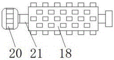
FIG. 2 is a schematic view of the crushing roller of the present invention;
fig. 3 is a side sectional view of a second motor structure of the present invention.
In the figure: the device comprises a box body 1, a first guide plate 2, a third through hole 3, a discharge pipe 4, a water outlet pipe 5, a water storage tank 6, a wind outlet pipe 7, a water inlet pipe 8, a suction fan 9, an air inlet pipe 10, a feed pipe 11, a first through hole 12, a connecting plate 13, a supporting plate 14, a first frame body 15, a second through hole 16, a crushing barrel 17, a crushing roller 18, a second frame body 19, a second motor 20, a connecting rod 21, a fixing rod 22, a rotary table 23, a first bearing seat 24 and a first motor 25.
Detailed Description
The technical solutions in the embodiments of the present invention will be described clearly and completely with reference to the accompanying drawings in the embodiments of the present invention, and it is obvious that the described embodiments are only some embodiments of the present invention, not all embodiments. Based on the embodiments in the present invention, all other embodiments obtained by a person skilled in the art without creative work belong to the protection scope of the present invention.
Referring to fig. 1-3, a crushing device for waste concrete in building engineering comprises a box body 1, wherein a feeding pipe 11 is arranged on both sides of the top of the box body 1 in a penetrating manner, a first through hole 12 is arranged on the front side of the top surface of the box body 1, a supporting plate 14 is fixedly connected to the rear side of the top surface of the box body 1, the supporting plate 14 is arranged to support a first motor 25, the first motor 25 is fixedly connected to the surface of the top of the supporting plate 14, a rotating disc 23 is fixedly connected to the front side of the output end of the first motor 25, a first bearing seat 24 is fixedly connected to the front side of the supporting plate 14 and the rear side of the top surface of the box body 1, the inner cavity of the first bearing seat 24 is movably connected with the rotating disc 23 through a bearing, the first bearing seat 24 is arranged to support the rotating disc 23, the condition that the rotating disc 23 shakes is avoided, a fixing rod 22 is fixedly connected, the front side of the surface of the fixed rod 22 is sleeved with a connecting plate 13, the connecting mode of the connecting plate 13 and the fixed rod 22 is fixed connection, the bottom of the connecting plate 13 penetrates through the first through hole 12 and is fixedly connected with a crushing barrel 17, the bottom of the crushing barrel 17 extends to the inner cavity of the first frame body 15, the top of the inner cavity of the box body 1 is fixedly connected with the first frame body 15, the bottom of the first frame body 15 is semi-cylindrical, the surfaces of the front side and the rear side of the first frame body 15 are respectively and fixedly connected with the front side and the rear side of the inner cavity of the box body 1, the bottom of the inner cavity of the first frame body 15 is provided with a second through hole 16, the center of the inner cavity of the box body 1 is fixedly connected with a second frame body 19 positioned at the bottom of the first frame body 15, the surfaces of the front side and the rear side of the second frame body 19 are respectively and fixedly connected with, the rear side of the output end of the second motor 20 penetrates through the inner cavity of the second frame body 19 and is fixedly connected with a connecting rod 21, two sides of the back surface of the second frame body 19 are fixedly connected with second bearing seats, the rear side of the connecting rod 21 penetrates through the rear side of the second frame body 19 and is movably connected with the inner cavity of the second bearing seats through a bearing, the second bearing seats are arranged, the connecting rod 21 can be supported, a crushing roller 18 is sleeved on the surface of the connecting rod 21, the inner cavity of the crushing roller 18 is in interference fit with the surface of the connecting rod 21, a third through hole 3 is formed in the bottom of the inner cavity of the second frame body 19, a first guide plate 2 is fixedly connected with the bottom of the inner cavity of the box body 1, the left side of the first guide plate 2 is a tilting end, the second crushed concrete can be guided to the position near a discharge pipe 4 through the arrangement, an exhaust fan 9 is fixedly connected to the top of the right surface of the box body 1, the left side of the air inlet end of the exhaust fan 9 is communicated with an air inlet pipe 10, the left side of the air inlet pipe 10 penetrates through the inner cavity of the box body 1, the bottom of the air outlet end of the exhaust fan 9 is communicated with an air outlet pipe 7, a water storage tank 6 is fixedly connected to the center of the right surface of the box body 1 and is positioned at the bottom of the exhaust fan 9, a second guide plate is fixedly connected to the surface of the bottom of the inner cavity of the water storage tank 6, the left side of the second guide plate is a tilting end, dust in the water storage tank 6 can be guided to be near the water outlet pipe 5 by arranging the second guide plate, the bottom of the air outlet pipe 7 penetrates through the inner cavity of the water storage tank 6, a water inlet pipe 8 is arranged on the right side of the top of, through arranging the water outlet pipe 5 and the water valve, dust can be timely discharged according to requirements, a transparent window is inlaid at the top of the front surface of the water storage tank 6, through arranging the transparent window, the amount of dust accumulated in the water storage tank 6 can be observed constantly, the dust can be conveniently discharged when the dust is accumulated more, the back surface of the box body 1 is fixedly connected with a controller, the input ends of the first motor 25, the second motor 20 and the exhaust fan 9 are respectively and electrically connected with the output end of the controller, through arranging the third through hole 3, the water storage tank 6, the exhaust fan 9, the first through hole 12, the connecting plate 13, the first frame body 15, the second through hole 16, the crushing barrel 17, the crushing roller 18, the second frame body 19, the second motor 20, the connecting rod 21, the fixing rod 22, the turntable 23 and the second motor 25 to be matched with each other, the problems that the crushing effect is poor and a large amount of dust can be generated in, if the dust cannot be treated in time, the problem of serious environmental pollution can be caused.
When the device is used, the controller respectively controls the first motor 25, the second motor 20 and the exhaust fan 9 to work, then waste concrete is put into the discharge pipe 11 and enters the inner cavity of the first frame body 15, the second motor 25 rotates to drive the rotary disc 23 to rotate, so that the fixed rod 22 on the front surface of the rotary disc 23 rotates, the crushing cylinder 17 at the bottom of the rotary disc 23 is driven to rotate in the first frame body 15 by driving the connecting plate 13, primary crushing is realized, the concrete after primary crushing enters the second frame body 19 through the second through hole 16 at the bottom of the first frame body 15, the second motor 20 rotates to drive the connecting rod 21 to rotate, so that the crushing cylinder 18 on the surface of the connecting rod 21 rotates, secondary crushing is realized due to opposite rotation of the output ends of the two second motors 20, simultaneously, the exhaust fan 9 performs air draft, dust generated by crushing respectively enters the inner cavity of the water storage tank 6 through the air inlet pipe 10 and the air outlet pipe 7 and contacts with water inside, simultaneously through the gas outgoing of inlet tube 8 with the suction, observe the accumulation of dust in the storage water tank 6 through the transparent window, when the dust accumulation is more, stop the operation of air exhauster 9 through the controller to rotatory water valve makes dust and water all discharge through outlet pipe 5, closes the water valve, adds new water through inlet tube 8, realizes the clearance to the dust.
All parts used in the application document are standard parts and can be purchased from the market, the specific connection mode of each part adopts conventional means such as mature bolts, rivets, welding and the like in the prior art, machinery, parts and electrical equipment all adopt conventional models in the prior art, the equipment appearing in the text adopts 380V voltage for power supply, the circuit connection adopts the conventional connection mode in the prior art, and detailed description is not given.
In summary, the following steps: this building engineering abandonment concrete breaker, through setting up third through-hole 3, storage water tank 6, air exhauster 9, first through-hole 12, connecting plate 13, first framework 15, the second through-hole 16, broken section of thick bamboo 17, broken cylinder 18, second framework 19, second motor 20, connecting rod 21, dead lever 22, carousel 23 and second motor 25 mutually support, solved when broken abandonment concrete, crushing effect is relatively poor, and in crushing process, the concrete can produce a large amount of dusts, if can not in time handle the dust, then can cause the problem of environmental serious pollution.
Although embodiments of the present invention have been shown and described, it will be appreciated by those skilled in the art that changes, modifications, substitutions and alterations can be made in these embodiments without departing from the principles and spirit of the invention, the scope of which is defined in the appended claims and their equivalents.
Claims (7)
1. The utility model provides a building engineering waste concrete breaker, includes box (1), its characterized in that: the improved garbage bin is characterized in that inlet pipes (11) are arranged on two sides of the top of the bin body (1) in a penetrating mode, a first through hole (12) is formed in the front side of the top surface of the bin body (1), a supporting plate (14) is fixedly connected to the rear side of the top surface of the bin body (1), a first motor (25) is fixedly connected to the surface of the top of the supporting plate (14), a turntable (23) is fixedly connected to the front side of the output end of the first motor (25), a first bearing seat (24) is fixedly connected to the front side of the top surface of the bin body (1) and located on the front side of the supporting plate (14), an inner cavity of the first bearing seat (24) is movably connected with the turntable (23) through bearings, a fixing rod (22) is fixedly connected to the bottom of the front surface of the turntable (23), a connecting plate (13) is sleeved on the front side of the surface of the fixing rod (22), the top of the inner cavity of the box body (1) is fixedly connected with a first frame body (15), the bottom of the inner cavity of the first frame body (15) is provided with a second through hole (16), the center of the inner cavity of the box body (1) is positioned at the bottom of the first frame body (15) and is fixedly connected with a second frame body (19), two sides of the front surface of the second frame body (19) are fixedly connected with a second motor (20), the rear side of the output end of the second motor (20) penetrates through the inner cavity of the second frame body (19) and is fixedly connected with a connecting rod (21), the surface of the connecting rod (21) is sleeved with a crushing roller (18), the bottom of the inner cavity of the second frame body (19) is provided with a third through hole (3), the bottom of the inner cavity of the box body (1) is fixedly connected with a first guide plate (2), and the bottom of the, the utility model discloses a solar water heater, including box (1), air exhauster (9) on box (1) right side surface, the left side intercommunication of air exhauster (9) air inlet end has air-supply line (10), the inner chamber to box (1) is run through in the left side of air-supply line (10), the bottom intercommunication of air exhauster (9) air-out end has air-out pipe (7), the center department on box (1) right side surface just is located bottom fixedly connected with storage water tank (6) of air exhauster (9), the inner chamber to storage water tank (6) is run through to the bottom of air-out pipe (7), the right side at storage water tank (6) top is run through and is provided with inlet tube (8), the right side of storage water tank (6) inner chamber bottom is run.
2. The construction engineering waste concrete crushing device according to claim 1, wherein: the connection mode of the connection position of the connecting plate (13) and the fixing rod (22) is fixed connection, and the bottom of the crushing barrel (17) extends to the inner cavity of the first frame body (15).
3. The construction engineering waste concrete crushing device according to claim 1, wherein: the bottom of the first frame body (15) is semi-cylindrical, the surfaces of the front side and the rear side of the first frame body (15) are fixedly connected with the front side and the rear side of the inner cavity of the box body (1) respectively, and the surfaces of the front side and the rear side of the second frame body (19) are fixedly connected with the front side and the rear side of the inner cavity of the box body (1) respectively.
4. The construction engineering waste concrete crushing device according to claim 1, wherein: the inner cavity of the crushing roller (18) is in interference fit with the surface of the connecting rod (21), the two sides of the back surface of the second frame body (19) are fixedly connected with second bearing seats, and the rear side of the connecting rod (21) penetrates through the rear side of the second frame body (19) and is movably connected with the inner cavity of the second bearing seats through bearings.
5. The construction engineering waste concrete crushing device according to claim 1, wherein: the fixed surface of storage water tank (6) inner chamber bottom is connected with the second guide plate, and the left side of second guide plate is the perk end, the bottom of outlet pipe (5) extends to the bottom of storage water tank (6), and the bottom fixed mounting on outlet pipe (5) surface has the water valve, the top on storage water tank (6) positive surface is inlayed and is had the transparent window.
6. The construction engineering waste concrete crushing device according to claim 1, wherein: the left side of the first guide plate (2) is a tilting end, and the output ends of the two second motors (20) are opposite in rotation direction.
7. The construction engineering waste concrete crushing device according to claim 1, wherein: the back of the body surface fixedly connected with controller of box (1), the input of first motor (25), second motor (20) and air exhauster (9) respectively with the output electric connection of controller.
Priority Applications (1)
| Application Number | Priority Date | Filing Date | Title |
|---|---|---|---|
| CN201921557616.3U CN211385338U (en) | 2019-09-19 | 2019-09-19 | Building engineering abandonment concrete breaker |
Applications Claiming Priority (1)
| Application Number | Priority Date | Filing Date | Title |
|---|---|---|---|
| CN201921557616.3U CN211385338U (en) | 2019-09-19 | 2019-09-19 | Building engineering abandonment concrete breaker |
Publications (1)
| Publication Number | Publication Date |
|---|---|
| CN211385338U true CN211385338U (en) | 2020-09-01 |
Family
ID=72219533
Family Applications (1)
| Application Number | Title | Priority Date | Filing Date |
|---|---|---|---|
| CN201921557616.3U Active CN211385338U (en) | 2019-09-19 | 2019-09-19 | Building engineering abandonment concrete breaker |
Country Status (1)
| Country | Link |
|---|---|
| CN (1) | CN211385338U (en) |
Cited By (2)
| Publication number | Priority date | Publication date | Assignee | Title |
|---|---|---|---|---|
| CN114082762A (en) * | 2021-10-14 | 2022-02-25 | 河南农业大学 | A construction waste treatment device for building engineering waste material is recycled |
| CN115350789A (en) * | 2022-07-27 | 2022-11-18 | 威海市东旭西洋参有限公司 | Crushing device and method for ginseng extract tea processing |
-
2019
- 2019-09-19 CN CN201921557616.3U patent/CN211385338U/en active Active
Cited By (3)
| Publication number | Priority date | Publication date | Assignee | Title |
|---|---|---|---|---|
| CN114082762A (en) * | 2021-10-14 | 2022-02-25 | 河南农业大学 | A construction waste treatment device for building engineering waste material is recycled |
| CN114082762B (en) * | 2021-10-14 | 2022-08-26 | 河南农业大学 | A construction waste treatment device for building engineering waste material is recycled |
| CN115350789A (en) * | 2022-07-27 | 2022-11-18 | 威海市东旭西洋参有限公司 | Crushing device and method for ginseng extract tea processing |
Similar Documents
| Publication | Publication Date | Title |
|---|---|---|
| CN211385338U (en) | Building engineering abandonment concrete breaker | |
| CN210340691U (en) | Automobile glass cutting and recycling device | |
| CN208260870U (en) | Building waste grinding device with dust processing | |
| CN210646764U (en) | Construction waste treatment device | |
| CN212918619U (en) | Sweeps collection device for machining center | |
| CN207279642U (en) | A kind of domestic garbage disposer easy to deslagging | |
| CN212855450U (en) | Material stirring device for municipal house construction | |
| CN210701671U (en) | Soil thermal desorption prosthetic devices | |
| CN207357291U (en) | A kind of environment-friendly garbage waste treatment apparatus | |
| CN210910592U (en) | Be applied to refuse treatment device of environmental protection building | |
| CN209380946U (en) | A kind of timber edge-cutting device of recyclable clast | |
| CN112496005A (en) | Energy-saving and environment-friendly garbage treatment equipment and method thereof | |
| CN214051767U (en) | Construction waste retrieves and uses high-efficient breaker | |
| CN214107219U (en) | Genetic engineering laboratory is with reducing mechanism's clearance mechanism | |
| CN218119766U (en) | Waste incineration power generation debugging device | |
| CN212595980U (en) | Environment-friendly biomass fuel processing device | |
| CN219308813U (en) | Concrete recycling device | |
| CN215586594U (en) | Garbage disposal device for construction waste | |
| CN210729653U (en) | A breaker for domestic waste handles usefulness | |
| CN211988867U (en) | Crushing device for solid garbage treatment | |
| CN211781098U (en) | Cement kiln garbage distribution treatment device | |
| CN213315482U (en) | Power plant is useless admittedly handles with high-efficient reducing mechanism | |
| CN217616788U (en) | A carbomorphism device for kitchen garbage | |
| CN216296510U (en) | Green building engineering refuse treatment is with smashing efficient rubbish rubbing crusher | |
| CN216868489U (en) | High-efficiency desulfurization household garbage incineration power generation device |
Legal Events
| Date | Code | Title | Description |
|---|---|---|---|
| GR01 | Patent grant | ||
| GR01 | Patent grant |