CN211366171U - Automatic clamping device for memory bank packaging box cover - Google Patents
Automatic clamping device for memory bank packaging box cover Download PDFInfo
- Publication number
- CN211366171U CN211366171U CN201922467660.1U CN201922467660U CN211366171U CN 211366171 U CN211366171 U CN 211366171U CN 201922467660 U CN201922467660 U CN 201922467660U CN 211366171 U CN211366171 U CN 211366171U
- Authority
- CN
- China
- Prior art keywords
- fixedly connected
- lead screw
- groove
- plate
- motor
- Prior art date
- Legal status (The legal status is an assumption and is not a legal conclusion. Google has not performed a legal analysis and makes no representation as to the accuracy of the status listed.)
- Active
Links
Images


Abstract
The utility model belongs to the technical field of memory bank packaging box covers, in particular to an automatic clamping device for memory bank packaging box covers, which comprises a bottom plate, wherein the top of the bottom plate is fixedly connected with a fixed plate, and the top of the fixed plate is provided with a second groove; the utility model discloses, work through the electric putter among the adjusting part, shorten along with electric putter's extension, the movable action with the help of universal joint and third round pin axle, the realization drives the second support arm and goes on the purpose of activity from top to bottom, the device adopts drive assembly, the third lead screw, the second lead screw sleeve, first motor and adjusting part, the height of centre gripping to first grip block and second grip block has been reached, the adjustment in angle and position, the nimble use to the device has been realized, the centre gripping transportation efficiency has been improved greatly, through setting up the biax motor, first lead screw, the second lead screw, the first lead screw sleeve, first grip block and second grip block, reached and got the automatic clamp of depositing strip packing lid, practice thrift the cost of labor.
Description
Technical Field
The utility model belongs to the technical field of memory strip packing box cover, concretely relates to device is got to automatic clamp of memory strip packing box cover.
Background
The memory bank, also called a random access memory, is an internal memory that directly exchanges data with the CPU, and is usually used as a temporary data storage medium for an operating system or other programs in operation, and information can be written or read from any one designated address at any time when the memory bank is in operation.
At present in the memory stick packing lid through assembly line transportation production process, need get the lid after accomplishing and put, get to put now and adopt the manual work to take off and place mostly, greatly increased workman's intensity of labour and cost of labor, be unfavorable for simultaneously improving to press from both sides and get efficiency, bring very big inconvenience for the use.
SUMMERY OF THE UTILITY MODEL
To solve the problems set forth in the background art described above. The utility model provides a device is got to automatic clamp of DRAM packing lid has the regulation clamp of being convenient for and gets lid and press from both sides the characteristics of getting efficiently.
In order to achieve the above object, the utility model provides a following technical scheme: the automatic clamping device for the memory stick packaging box cover comprises a bottom plate, wherein the top of the bottom plate is fixedly connected with a fixed plate, the top of the fixed plate is provided with a second groove, the bottom of the inner wall of the second groove is fixedly connected with a second bearing, a second rotating shaft penetrates through the second bearing, the top end of the second rotating shaft is fixedly connected with a third lead screw, the surface of the second rotating shaft is fixedly connected with a driving assembly, the top of the bottom plate is fixedly connected with a shell, the driving assembly is positioned in the shell, the surface of the third lead screw is in threaded connection with a second lead screw sleeve, the side surface of the inner wall of the second groove is provided with a first sliding groove, a first sliding block is in sliding connection with the first sliding groove, the first sliding block is fixedly connected with the second lead screw sleeve, the top of the second lead screw sleeve is fixedly connected with a supporting block, the inner wall of the first groove is fixedly connected with a first motor, the output shaft of the first motor is fixedly connected with a first support arm, the first support arm is movably connected with a second support arm through a universal joint, the bottom of the second support arm is fixedly connected with a connecting plate, the bottom of the connecting plate is provided with a third groove, the inner wall of the third groove is fixedly connected with a double-shaft motor, two output shafts of the double-shaft motor are respectively and fixedly connected with a first lead screw and a second lead screw, the separated ends of the first lead screw and the second lead screw are respectively and fixedly connected with a first rotating shaft, the surface of the first rotating shaft is sleeved with a first bearing, the first bearing is fixedly connected with the inner wall of the third groove, the surfaces of the first lead screw and the second lead screw are respectively and threadedly connected with a first lead screw sleeve, the top of the third groove is provided with a second chute, and two second sliding blocks are slidably connected in the second, the second slider is fixedly connected with the first lead screw sleeve, the bottom of the first lead screw sleeve is fixedly connected with a connecting block, the connecting block is respectively and movably connected with a first clamping plate and a second clamping plate through a second pin shaft, the first clamping plate and the second clamping plate are movably connected through a first pin shaft, and an adjusting assembly is fixedly connected between the first supporting arm and the second supporting arm.
Preferably, the adjusting part includes two fixed blocks, two movable blocks, two third round pin axles and electric putter, two the fixed block is fixed connection respectively on first support arm and second support arm, two the fixed plate all has the movable block, two through third round pin axle swing joint the opposite face fixedly connected with electric putter of movable block.
Preferably, the driving assembly comprises a driving motor, a third bearing, a driving bevel gear and a driven bevel gear, the driving motor is fixedly connected inside the shell, the third bearing is fixedly connected to the side face of the fixing plate, an output shaft of the driving motor penetrates through the third bearing and is fixedly connected with the driving bevel gear, the driving bevel gear is meshed with the driven bevel gear, and the driven bevel gear is fixedly connected to the surface of the second rotating shaft.
Preferably, the top of bottom plate sets up button switch, button switch passes through wire electric connection with first motor, biax motor, driving motor and electric putter.
Preferably, the opposite surfaces of the first clamping plate and the second clamping plate are fixedly connected with anti-slip pads, and the surface threads of the first screw rod and the second screw rod are opposite in direction.
Preferably, an annular groove is formed in the top of the supporting block, a pulley is connected in the annular groove in a sliding mode, and the pulley is fixedly connected to the bottom of the first supporting arm.
Preferably, the bottom of the bottom plate is fixedly connected with four rollers, and the four rollers are respectively positioned at the positions, close to four corners, of the bottom plate.
Preferably, the top of the bottom plate is fixedly connected with a support frame, and the other end of the support frame is fixedly connected to the surface of the fixing plate.
Compared with the prior art, the beneficial effects of the utility model are that:
the utility model realizes the purpose of driving the second supporting arm to move up and down by the work of the electric push rod in the adjusting component along with the extension shortening of the electric push rod and by the action of the universal joint and the third pin shaft, thereby achieving the adjustment of the clamping angle, the driving motor in the driving component can drive the driving bevel gear to rotate, the third screw rod is driven to rotate by the meshing rotation of the driving bevel gear and the driven bevel gear and the second rotating shaft, the supporting block is driven to move up and down by the sliding action of the first slider and the first chute, thereby achieving the purpose of driving the first clamping plate and the second clamping plate to adjust the height, the double-shaft motor works, the first screw rod and the second screw rod can be driven to rotate, the sliding action of the second slider and the second chute is utilized, and by the action of the first pin shaft and the second pin shaft, reach to drive first grip block and second grip block and open and shut along with the removal about the second lead screw sleeve, the realization is to the centre gripping of packing lid, the device adopts drive assembly, the third lead screw, the second lead screw sleeve, first motor and adjusting part, the clamping height to first grip block and second grip block has been reached, the adjustment of angle and position, the nimble use to the device has been realized, the centre gripping transportation efficiency has been improved greatly, through setting up the biax motor, first lead screw, the second lead screw, first lead screw sleeve, first grip block and second grip block, reached and got the automatic clamp of depositing strip packing lid, practice thrift the cost of labor, whole device is rational in infrastructure, high durability and convenient use, therefore, the clothes hanger is strong in practicability.
Drawings
The accompanying drawings are included to provide a further understanding of the invention, and are incorporated in and constitute a part of this specification, illustrate embodiments of the invention, and together with the description serve to explain the invention and not to limit the invention. In the drawings:
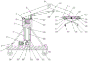
fig. 1 is a schematic structural view of a front view section of the present invention;
FIG. 2 is a schematic structural diagram of an adjusting assembly of the present invention;
fig. 3 is a schematic structural diagram of the driving assembly of the present invention;
in the figure: 1. a base plate; 2. a support frame; 3. a housing; 4. a first chute; 5. a support block; 6. a first motor; 7. a first groove; 8. a first support arm; 9. a universal joint; 10. a second support arm; 11. a connecting plate; 12. a second chute; 13. a second slider; 14. a first bearing; 15. a first rotating shaft; 16. a first lead screw; 17. a double-shaft motor; 18. a first pin shaft; 19. a non-slip mat; 20. a first clamping plate; 21. a second lead screw; 22. a second pin shaft; 23. connecting blocks; 24. a first lead screw sleeve; 25. a second clamping plate; 26. an adjustment assembly; 261. a fixed block; 262. a third pin shaft; 263. an electric push rod; 264. a movable block; 27. a pulley; 28. an annular groove; 29. a second lead screw sleeve; 30. a second groove; 31. a roller; 32. a first slider; 33. a fixing plate; 34. a second bearing; 35. a second rotating shaft; 36. a drive assembly; 361. a drive motor; 362. a third bearing; 363. a drive bevel gear; 364. a driven bevel gear; 37. a third groove; 38. a push button switch; 39. and a third screw rod.
Detailed Description
The technical solutions in the embodiments of the present invention will be described clearly and completely with reference to the accompanying drawings in the embodiments of the present invention, and it is obvious that the described embodiments are only some embodiments of the present invention, not all embodiments. Based on the embodiments in the present invention, all other embodiments obtained by a person skilled in the art without creative work belong to the protection scope of the present invention.
Examples
Referring to fig. 1-3, the present invention provides the following technical solutions: the automatic clamping device for the memory stick packaging box cover comprises a base plate 1, a fixing plate 33 is fixedly connected to the top of the base plate 1, a second groove 30 is formed in the top of the fixing plate 33, a second bearing 34 is fixedly connected to the bottom of the inner wall of the second groove 30, a second rotating shaft 35 penetrates through the second bearing 34, a third lead screw 39 is fixedly connected to the top end of the second rotating shaft 35, a driving assembly 36 is fixedly connected to the surface of the second rotating shaft 35, a shell 3 is fixedly connected to the top of the base plate 1, the driving assembly 36 is located inside the shell 3, a second lead screw sleeve 29 is in threaded connection with the surface of the third lead screw 39, a first sliding groove 4 is formed in the side surface of the inner wall of the second groove 30, a first sliding block 32 is in sliding connection with the first sliding groove 4, and the sliding effect of the first sliding block 32 can be matched with the second lead screw 29 to move up and down more, the first slider 32 is fixedly connected with the second lead screw sleeve 29, the top of the second lead screw sleeve 29 is fixedly connected with the supporting block 5, the top of the supporting block 5 is provided with a first groove 7, the inner wall of the first groove 7 is fixedly connected with a first motor 6, the first motor 6 works, and by means of the sliding fit of the pulley 27 and the annular groove 28, the first supporting arm 8 and the second supporting arm 10 can drive the first clamping plate 20 and the second clamping plate 25 to rotate, so as to realize the adjustment of the clamping direction, the output shaft of the first motor 6 is fixedly connected with the first supporting arm 8, the first supporting arm 8 is movably connected with the second supporting arm 10 through a universal joint 9, the bottom of the second supporting arm 10 is fixedly connected with the connecting plate 11, the bottom of the connecting plate 11 is provided with a third groove 37, and the inner wall of the third groove 37 is fixedly connected with a double-shaft motor 17, the double-shaft motor 17 works to drive the first lead screw 16 and the second lead screw 21 to rotate, the first clamping plate 20 and the second clamping plate 25 are driven to open and close along with the left and right movement of the second lead screw sleeve 29 by means of the sliding action of the second sliding block 13 and the second sliding chute 12 and by means of the moving action of the first pin shaft 18 and the second pin shaft 22, so as to clamp the packaging box cover, the first lead screw 16 and the second lead screw 21 are fixedly connected to two output shafts of the double-shaft motor 17 respectively, the separated ends of the first lead screw 16 and the second lead screw 21 are fixedly connected with the first rotating shaft 15, the surface of the first rotating shaft 15 is sleeved with the first bearing 14, the first bearing 14 is fixedly connected to the inner wall of the third groove 37, the surfaces of the first lead screw 16 and the second lead screw 21 are both in threaded connection with the first lead screw sleeve 24, the top of the third groove 37 is provided with the second sliding chute 12, the sliding connection has two second sliders 13 in the second chute 12, the second slider 13 and a first lead screw sleeve 24 fixed connection, the bottom fixedly connected with connecting block 23 of the first lead screw sleeve 24, two the connecting block 23 all has a first clamping plate 20 and a second clamping plate 25 through a second pin 22 respectively swing joint, the first clamping plate 20 and the second clamping plate 25 are through a first pin 18 swing joint, a regulating assembly 26 is fixedly connected between the first supporting arm 8 and the second supporting arm 10, the device adopts a driving assembly 36, a third lead screw 39, a second lead screw sleeve 29, a first motor 6 and a regulating assembly 26, the adjustment of the clamping height, angle and direction of the first clamping plate 20 and the second clamping plate 25 is achieved, the flexible use of the device is realized, the clamping transfer efficiency is greatly improved, and the clamping height, angle and direction of the device are adjusted by arranging a double-shaft motor 17, First lead screw 16, second lead screw 21, first lead screw sleeve 24, first grip block 20 and second grip block 25, reached the automatic clamp of getting to memory bank packing box lid, practiced thrift the cost of labor, whole device is rational in infrastructure, convenient to use, and the practicality is strong.
Concretely, adjusting part 26 includes two fixed blocks 261, two movable blocks 264, two third round pin axles 262 and electric putter 263, two fixed block 261 fixed connection respectively is on first support arm 8 and second support arm 10, two fixed plate 33 all has a movable block 264, two through third round pin axle 262 swing joint the opposite face fixedly connected with electric putter 263 of movable block 264, electric putter 263 work in the adjusting part 26 shortens along with electric putter 263's extension, with the help of universal joint 9 and third round pin axle 262's effect of moving, realizes driving second support arm 10 and carries out the purpose of activity from top to bottom, and then reaches the regulation to the centre gripping angle.
Specifically, the driving assembly 36 includes a driving motor 361, a third bearing 362, a driving bevel gear 363, and a driven bevel gear 364, the driving motor 361 is fixedly connected to the inside of the housing 3, the third bearing 362 is fixedly connected to the side of the fixing plate 33, an output shaft of the driving motor 361 passes through the third bearing 362 and is fixedly connected with a drive bevel gear 363, the driving bevel gear 363 is engaged with the driven bevel gear 364, the driven bevel gear 364 is fixedly connected to the surface of the second rotating shaft 35, the driving motor 361 of the driving assembly 36 can drive the driving bevel gear 363 to rotate, the third screw rod 39 is driven to rotate by the second rotating shaft 35 through the meshing rotation of the driving bevel gear 363 and the driven bevel gear 364, the second screw rod sleeve 29 can drive the supporting block 5 to move up and down by the sliding action of the first sliding block 32 and the first sliding chute 4, thereby achieving the purpose of driving the first clamping plate 20 and the second clamping plate 25 to adjust the height.
Specifically, bottom plate 1's top sets up button switch 38, button switch 38 passes through wire electric connection with first motor 6, biax motor 17, driving motor 361 and electric putter 263, through setting up button switch 38, is convenient for the staff to control the operating condition of first motor 6, biax motor 17, driving motor 361 and electric putter 263 respectively.
Specifically, the anti-slip pads 19 are fixedly connected to the opposite surfaces of the first clamping plate 20 and the second clamping plate 25, and the surface threads of the first screw rod 16 and the second screw rod 21 are opposite in direction.
Specifically, ring channel 28 has been seted up at the top of supporting shoe 5, sliding connection has pulley 27 in the ring channel 28, pulley 27 fixed connection is in the bottom of first support arm 8, through setting up ring channel 28 and pulley 27, can cooperate first motor 6 to drive first support arm 8 and rotate more stably.
Specifically, four gyro wheels 31 of bottom plate 1's bottom fixedly connected with, four gyro wheel 31 is located the position that bottom plate 1 bottom is close to the four corners respectively, can drive the device through gyro wheel 31 and carry out the position removal, facilitates the use.
Specifically, the top fixedly connected with support frame 2 of bottom plate 1, the other end fixed connection of support frame 2 is on the surface of fixed plate 33, through setting up support frame 2, can strengthen the stability of fixed plate 33.
The utility model discloses a theory of operation and use flow: when the utility model is used, firstly, the device is moved to the assembly line through the roller 31, and the second supporting arm 10 drives the first clamping plate 20 and the second clamping plate 25 to be positioned above the assembly line, then the driving motor 361 is controlled to work through the button switch 38, the second rotating shaft 35 drives the third lead screw 39 to rotate through the meshing rotation of the driving bevel gear 363 and the driven bevel gear 364, the second lead screw sleeve 29 drives the supporting block 5 to move up and down through the sliding fit of the first chute 4 and the first slider 32, and then the first clamping plate 20 and the second clamping plate 25 are driven to move up and down, then the electric push rod 263 is controlled to work through the button switch 38, the first clamping plate 20 and the second clamping plate 25 are driven to move up and down through the second supporting arm 10 by the movable fit of the universal joint 9 and the third pin 262, the adjustment of the clamping angle is realized, after the adjustment is finished, through the work of button switch 38 control biax motor 17, drive first lead screw 16 and second lead screw 21 and rotate, make first lead screw sleeve 24 drive connecting block 23 and remove about, with the help of the mobile effect of first round pin axle 18 and second round pin axle 22, realize that first grip block 20 and second grip block 25 are close to each other, the realization is got the clamp of packing box lid, then control first motor 6 work through button switch 38, drive first grip block 20 and second grip block 25 through first support arm 8 and second support arm 10 and rotate, the realization is to the transportation of packing box lid can.
Finally, it should be noted that: although the present invention has been described in detail with reference to the foregoing embodiments, it will be apparent to those skilled in the art that modifications may be made to the embodiments described in the foregoing embodiments, or equivalents may be substituted for elements thereof. Any modification, equivalent replacement, or improvement made within the spirit and principle of the present invention should be included in the protection scope of the present invention.
Claims (8)
1. Automatic clamping device of DRAM packing box lid, including bottom plate (1), its characterized in that: the top of the bottom plate (1) is fixedly connected with a fixing plate (33), a second groove (30) is formed in the top of the fixing plate (33), a second bearing (34) is fixedly connected to the bottom of the inner wall of the second groove (30), a second rotating shaft (35) penetrates through the second bearing (34), a third lead screw (39) is fixedly connected to the top end of the second rotating shaft (35), a driving assembly (36) is fixedly connected to the surface of the second rotating shaft (35), a shell (3) is fixedly connected to the top of the bottom plate (1), the driving assembly (36) is located inside the shell (3), a second lead screw sleeve (29) is in threaded connection with the surface of the third lead screw (39), a first sliding groove (4) is formed in the side face of the inner wall of the second groove (30), and a first sliding block (32) is slidably connected to the first sliding groove (4), the first slider (32) is fixedly connected with a second lead screw sleeve (29), the top of the second lead screw sleeve (29) is fixedly connected with a supporting block (5), the top of the supporting block (5) is provided with a first groove (7), the inner wall of the first groove (7) is fixedly connected with a first motor (6), the output shaft of the first motor (6) is fixedly connected with a first supporting arm (8), the first supporting arm (8) is movably connected with a second supporting arm (10) through a universal joint (9), the bottom of the second supporting arm (10) is fixedly connected with a connecting plate (11), the bottom of the connecting plate (11) is provided with a third groove (37), the inner wall of the third groove (37) is fixedly connected with a double-shaft motor (17), and two output shafts of the double-shaft motor (17) are respectively and fixedly connected with a first lead screw (16) and a second lead screw (21), the two ends of the first screw rod (16) and the second screw rod (21) which are separated from each other are fixedly connected with a first rotating shaft (15), a first bearing (14) is sleeved on the surface of the first rotating shaft (15), the first bearing (14) is fixedly connected to the inner wall of a third groove (37), the surfaces of the first screw rod (16) and the second screw rod (21) are both in threaded connection with a first screw rod sleeve (24), the top of the third groove (37) is provided with a second sliding chute (12), the second sliding chute (12) is in sliding connection with two second sliding blocks (13), the second sliding blocks (13) are fixedly connected with the first screw rod sleeve (24), the bottom of the first screw rod sleeve (24) is fixedly connected with a connecting block (23), and the two connecting blocks (23) are both movably connected with a first clamping plate (20) and a second clamping plate (25) through second pin shafts (22), the first clamping plate (20) and the second clamping plate (25) are movably connected through a first pin shaft (18), and an adjusting assembly (26) is fixedly connected between the first supporting arm (8) and the second supporting arm (10).
2. The automatic clamping device for the memory bank packaging box cover according to claim 1, wherein: adjusting part (26) includes two fixed blocks (261), two movable blocks (264), two third round pin axles (262) and electric putter (263), two fixed block (261) fixed connection respectively is on first support arm (8) and second support arm (10), two fixed plate (33) all have movable block (264), two through third round pin axle (262) swing joint the opposite face fixedly connected with electric putter (263) of movable block (264).
3. The automatic clamping device for the memory bank packaging box cover according to claim 1, wherein: the driving assembly (36) comprises a driving motor (361), a third bearing (362), a driving bevel gear (363) and a driven bevel gear (364), the driving motor (361) is fixedly connected inside the shell (3), the third bearing (362) is fixedly connected to the side surface of the fixing plate (33), an output shaft of the driving motor (361) penetrates through the third bearing (362) and is fixedly connected with the driving bevel gear (363), the driving bevel gear (363) is meshed with the driven bevel gear (364), and the driven bevel gear (364) is fixedly connected to the surface of the second rotating shaft (35).
4. The automatic clamping device for the memory bank packaging box cover according to claim 1, wherein: the top of bottom plate (1) sets up button switch (38), button switch (38) pass through wire electric connection with first motor (6), biax motor (17), driving motor (361) and electric putter (263).
5. The automatic clamping device for the memory bank packaging box cover according to claim 1, wherein: the anti-skidding mats (19) are fixedly connected to the opposite surfaces of the first clamping plate (20) and the second clamping plate (25), and the surface threads of the first screw rod (16) and the second screw rod (21) are opposite in direction.
6. The automatic clamping device for the memory bank packaging box cover according to claim 1, wherein: annular groove (28) have been seted up at the top of supporting shoe (5), sliding connection has pulley (27) in annular groove (28), pulley (27) fixed connection is in the bottom of first supporting arm (8).
7. The automatic clamping device for the memory bank packaging box cover according to claim 1, wherein: the bottom of the bottom plate (1) is fixedly connected with four rollers (31), and the four rollers (31) are respectively positioned at the positions, close to four corners, of the bottom plate (1).
8. The automatic clamping device for the memory bank packaging box cover according to claim 1, wherein: the top fixedly connected with support frame (2) of bottom plate (1), the other end fixed connection of support frame (2) is on the surface of fixed plate (33).
Priority Applications (1)
| Application Number | Priority Date | Filing Date | Title |
|---|---|---|---|
| CN201922467660.1U CN211366171U (en) | 2019-12-31 | 2019-12-31 | Automatic clamping device for memory bank packaging box cover |
Applications Claiming Priority (1)
| Application Number | Priority Date | Filing Date | Title |
|---|---|---|---|
| CN201922467660.1U CN211366171U (en) | 2019-12-31 | 2019-12-31 | Automatic clamping device for memory bank packaging box cover |
Publications (1)
| Publication Number | Publication Date |
|---|---|
| CN211366171U true CN211366171U (en) | 2020-08-28 |
Family
ID=72171562
Family Applications (1)
| Application Number | Title | Priority Date | Filing Date |
|---|---|---|---|
| CN201922467660.1U Active CN211366171U (en) | 2019-12-31 | 2019-12-31 | Automatic clamping device for memory bank packaging box cover |
Country Status (1)
| Country | Link |
|---|---|
| CN (1) | CN211366171U (en) |
Cited By (3)
| Publication number | Priority date | Publication date | Assignee | Title |
|---|---|---|---|---|
| CN111913098A (en) * | 2020-09-14 | 2020-11-10 | 温州宇岚科技有限公司 | Detection apparatus for electrical automation equipment |
| CN112792832A (en) * | 2021-01-23 | 2021-05-14 | 苏州浪潮智能科技有限公司 | Memory bank grabbing device |
| CN113602787A (en) * | 2021-06-16 | 2021-11-05 | 安徽金阳金属结构工程有限公司 | Conveyer of steel construction H shaped steel |
-
2019
- 2019-12-31 CN CN201922467660.1U patent/CN211366171U/en active Active
Cited By (5)
| Publication number | Priority date | Publication date | Assignee | Title |
|---|---|---|---|---|
| CN111913098A (en) * | 2020-09-14 | 2020-11-10 | 温州宇岚科技有限公司 | Detection apparatus for electrical automation equipment |
| CN112792832A (en) * | 2021-01-23 | 2021-05-14 | 苏州浪潮智能科技有限公司 | Memory bank grabbing device |
| CN112792832B (en) * | 2021-01-23 | 2022-06-14 | 苏州浪潮智能科技有限公司 | Memory bank grabbing device |
| CN113602787A (en) * | 2021-06-16 | 2021-11-05 | 安徽金阳金属结构工程有限公司 | Conveyer of steel construction H shaped steel |
| CN113602787B (en) * | 2021-06-16 | 2023-05-09 | 安徽金阳金属结构工程有限公司 | Conveyer of steel construction H shaped steel |
Similar Documents
| Publication | Publication Date | Title |
|---|---|---|
| CN211366171U (en) | Automatic clamping device for memory bank packaging box cover | |
| CN207534562U (en) | A kind of grinding device for facilitating fixed section bar | |
| CN206738124U (en) | A kind of refrigeration compressor easy to remove | |
| CN109353954B (en) | Three-dimensional parking equipment installation device | |
| CN212475437U (en) | Make things convenient for coiling device of different width non-woven fabrics of rolling | |
| CN111084492A (en) | Computer assembling workbench for computer technology research and development and method thereof | |
| CN209898908U (en) | Base device that intelligent robot used | |
| CN213036911U (en) | Novel box turning mechanism | |
| CN209561563U (en) | A kind of efficient tape sticking device of lithium battery | |
| CN111332959A (en) | Multi-functional hydraulic engineering pipeline handling device | |
| CN211225236U (en) | Automatic box cover conveying device | |
| CN206088618U (en) | Automatic take -up of charging cable | |
| CN209110715U (en) | Grinding device is used in a kind of processing of auto parts and components | |
| CN211569374U (en) | Automatic carrying device for memory bank packaging box | |
| CN211254598U (en) | Novel cloth rolling equipment for tailoring | |
| CN212149564U (en) | Packaging machine capable of guaranteeing packaging quality | |
| CN211077979U (en) | PVC pipe winding device convenient to use | |
| CN214494126U (en) | Industrial electrical equipment transport case | |
| CN207345891U (en) | A kind of clothes closet mobile device | |
| CN214772052U (en) | Robot pile up neatly device convenient to adjusting position | |
| CN220950603U (en) | Take-up device for clothing manufacture | |
| CN212024350U (en) | Electric power cable coiling apparatus | |
| CN206014080U (en) | A kind of weaving Winder | |
| CN216297995U (en) | Clamping device of radial drilling machine workbench | |
| CN211333272U (en) | Modular multi-group robot integration moving device |
Legal Events
| Date | Code | Title | Description |
|---|---|---|---|
| GR01 | Patent grant | ||
| GR01 | Patent grant |