CN211162277U - Clamp for numerical control wire cutting machining - Google Patents
Clamp for numerical control wire cutting machining Download PDFInfo
- Publication number
- CN211162277U CN211162277U CN201920097645.XU CN201920097645U CN211162277U CN 211162277 U CN211162277 U CN 211162277U CN 201920097645 U CN201920097645 U CN 201920097645U CN 211162277 U CN211162277 U CN 211162277U
- Authority
- CN
- China
- Prior art keywords
- conical surface
- clamp body
- taper hole
- fixation clamp
- plate
- Prior art date
- Legal status (The legal status is an assumption and is not a legal conclusion. Google has not performed a legal analysis and makes no representation as to the accuracy of the status listed.)
- Expired - Fee Related
Links
- 238000005520 cutting process Methods 0.000 title claims abstract description 22
- 238000003754 machining Methods 0.000 title claims abstract description 9
- 230000004418 eye rotation Effects 0.000 claims abstract description 3
- 239000012212 insulator Substances 0.000 claims description 7
- 238000007789 sealing Methods 0.000 claims description 7
- 238000005516 engineering process Methods 0.000 description 4
- 238000010586 diagram Methods 0.000 description 3
- 238000000034 method Methods 0.000 description 3
- 239000002184 metal Substances 0.000 description 2
- 238000003825 pressing Methods 0.000 description 2
- 241001391944 Commicarpus scandens Species 0.000 description 1
- 238000010276 construction Methods 0.000 description 1
- 238000009760 electrical discharge machining Methods 0.000 description 1
- 238000009434 installation Methods 0.000 description 1
- 238000004519 manufacturing process Methods 0.000 description 1
- 238000012986 modification Methods 0.000 description 1
- 230000004048 modification Effects 0.000 description 1
Images


Landscapes
- Electrical Discharge Machining, Electrochemical Machining, And Combined Machining (AREA)
Abstract
The utility model discloses an anchor clamps for numerical control wire-electrode cutting processing, including mount pad, the fixation clamp body and swivel work head, the fixation clamp body is L shape, and the concrete bottom plate of fixation clamp passes through the bolt fixed with the mount pad, and the outside of fixation clamp body riser is located to the swivel work head, and the swivel work head is connected through first conical surface locating pin and second conical surface locating pin with the fixation clamp body, and the outside of fixation clamp body riser is equipped with location taper hole, dead eye and graduation taper hole, and the swivel work head passes through the mandrel and is connected with the dead eye rotation, first conical surface locating pin and location taper hole cooperation, second conical surface locating pin and graduation taper hole cooperation are established ten graduation taper holes on the fixation clamp body, and conical surface locating pin and the cooperation of the taper hole of difference can make the swivel work head obtain different angles, and utilize the small amplitude slope between the upper and lower guide pulley 0 ~ 5 of lathe slope simultaneously, can realize processing 0 ~ 45 arbitrary angle part, improve the machining precision of work piece.
Description
Technical Field
The utility model belongs to the technical field of the numerical control wire-electrode cutting processing technique and specifically relates to a anchor clamps are used in numerical control wire-electrode cutting processing.
Background
The numerical control wire cutting technology is to use a continuously moving thin metal wire called as an electrode wire as an electrode to perform pulse spark erosion on a workpiece to remove metal, and then to cut and form the workpiece. In the mold manufacturing industry, a numerical control linear cutting machine is an indispensable processing device, most of the numerical control linear cutting machine is used for bearing the processing of precision parts, large-angle parts often appear, the processing technology is complex, the processing difficulty is increased due to large angles, and the common traditional technology is used for realizing processing by using the upper and lower opposite functions of a slow-moving wire or processing angle type parts by using methods of a fast-moving wire, an inclined upper guide wheel and a inclined lower guide wheel and the like. When the processing technology is adopted, the processing speed is relatively slow, the processing cost is high, the processing precision is not ideal, and when the slow-moving wire cutting machine tool is adopted for processing, the wire electrode is easy to break in the processing process due to the fact that the angle to be processed is large. When a numerical control fast wire cutting machine tool is used for machining, the wire precision of the guide wheel can be reduced due to the fact that the upper guide wheel and the lower guide wheel which are deviated are used for machining, machining precision of machined parts is not high, and when the angle of a workpiece is too large, the upper guide wheel and the lower guide wheel which are deviated by the machine tool are limited, and machining cannot be achieved.
SUMMERY OF THE UTILITY MODEL
An object of the utility model is to provide an anchor clamps are used in numerical control wire-electrode cutting processing has solved the difficult processing problem of too big angle part of numerical control wire-electrode cutting, disposes various assistive devices simultaneously on this anchor clamps, but the work piece of the various shapes of centre gripping.
The utility model provides a numerical control is anchor clamps for wire-electrode cutting processing, its structure includes mount pad, the fixation clamp body and swivel work head, the fixation clamp body is L shape, and the concrete bottom plate of fixation clamp passes through the bolt and is fixed with the mount pad, the outside of fixation clamp body riser is located to the swivel work head, swivel work head is connected through first conical surface locating pin and second conical surface locating pin with the fixation clamp body, the outside of fixation clamp body riser is equipped with location taper hole, dead eye and graduation taper hole, the swivel work head passes through the mandrel and is connected with the dead eye rotation, first conical surface locating pin and location taper hole cooperation, second conical surface locating pin and graduation taper hole cooperation.
Further, the swivel work head is L shapes that comprise fixed plate and work piece mounting panel, the fixed plate is connected with the work piece mounting panel is perpendicular, one end is equipped with the primary shaft hole on the fixed plate, and the middle part is equipped with the secondary shaft hole, and the other end is equipped with the third shaft hole, the higher authority middle part and the side of work piece mounting panel are equipped with the V-arrangement groove of placing the work piece respectively, and the higher authority and the front side of work piece mounting panel are equipped with the screw hole respectively.
Furthermore, a V-shaped block is arranged on the workpiece mounting plate of the rotary workbench, and a V-shaped groove for clamping and placing the workpiece is arranged on the V-shaped block.
Further, a bearing hole is formed in the fixed clamp body, the sealing bearing is in interference fit with the bearing hole, and the mandrel on the rotating workbench is in interference fit with the sealing bearing on the fixed clamp body through a shaft hole in the rotating workbench.
Furthermore, the front part of the first conical surface positioning pin is a conical surface which can be matched with the positioning conical hole, the middle part of the first conical surface positioning pin is a cylindrical surface which is matched with a first shaft hole arranged on the rotary workbench, the tail part of the first conical surface positioning pin is a thread, the tail part of the first conical surface positioning pin is matched with a first nut through a second spring, the front part of the second conical surface positioning pin is a conical surface which is matched with the indexing conical hole, the middle part of the first conical surface positioning pin is a cylindrical surface which is matched with a third shaft hole arranged on the rotary workbench, and the tail part.
Furthermore, the specific riser outside one end of fixed clamp is equipped with a plurality of graduation taper holes, and every pitch-row is 5 degrees, and the upper portion is equipped with the round hole of a plurality of installation dead lever in the riser outside.
Furthermore, the mounting seat is composed of an upper flat plate, an insulator block and a lower flat plate, the insulator block is arranged between the upper flat plate and the lower flat plate, and a plurality of threaded holes are formed in the upper flat plate and the lower flat plate.
The utility model has the advantages that:
1. the utility model discloses ten graduation taper holes that set up on the fixation clamp body, every pitch-row is 5 degrees, and conical surface locating pin and the cooperation of the taper hole of difference can make the swivel work head obtain different angles, utilize the small amplitude slope between the upper and lower guide pulley of lathe slope 0 ~ 5 simultaneously, can realize processing 0 ~ 45 arbitrary angle part, improve the machining precision of work piece.
2. The utility model discloses be in the workable internal spline of horizontal position, all kinds of parts such as keyway rotating the workstation. But the cylindrical type part of centre gripping is gone up to the V-arrangement groove that sets up of swivel work head, and the V-arrangement groove has the automatic centering function, and processing batch part, and the repeated clamping precision is high, and the loading and unloading is nimble convenient.
3. The utility model discloses various assistive devices can be installed to the screw hole that sets up on the swivel work head, are satisfied with in the clamping demand of various parts.
Drawings
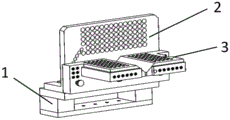
FIG. 1 is a perspective view of the present invention;
FIG. 2 is a front view of the present invention;
fig. 3 is a top view of the present invention;
fig. 4 is a schematic perspective view of the clamp of the present invention inclining 30 degrees for clamping a workpiece;
FIG. 5 is a schematic perspective view of the fixture for clamping a horizontal cylindrical workpiece according to the present invention;
FIG. 6 is a perspective view of the fixture for clamping a cylindrical workpiece in a vertical position;
fig. 7 is an exploded view of the clamp of the present invention;
fig. 8 is a perspective view of the fixing clip body of the present invention;
fig. 9 is a perspective view of the rotary table of the present invention;
fig. 10 is a perspective view of the mounting base of the present invention;
in the figure:
1. a mounting seat; 2. fixing the clamp body; 3. rotating the workbench; 4. a first nut; 5. a second nut; 6. a first spring; 7. a second spring; 8. a mandrel; 9. a first conical surface positioning pin; 10. sealing the bearing; 11. a second conical surface positioning pin; 12. a first bolt; 13. a second bolt; 14. a third bolt; 15. A V-shaped block; 16. fixing the rod; 17. a hold-down bolt; 18. roughly boring a cutter bar for a workpiece; 19. a workpiece limiting shaft; 20. a workpiece internal spline; 21. positioning the taper hole; 22. a bearing bore; 23. indexing the taper hole; 24. a first shaft hole; 25. a second shaft hole; 26. a third shaft hole; 27. an upper flat plate; 28. an insulator block; 29. a lower flat plate; 30. and a V-shaped groove.
Detailed Description
The following detailed description will be made of a clamp for numerical control wire-electrode cutting according to the present invention with reference to the accompanying drawings.
As shown in fig. 1 to 10, the utility model discloses an anchor clamps are used in numerical control wire-electrode cutting processing, its structure includes mount pad 1, the fixing clamp body 2 and swivel work head 3, the fixing clamp body 2 is L shape, and the bottom plate of the fixing clamp body 2 passes through the bolt fixed with mount pad 1, swivel work head 3 locates the outside of the fixing clamp body 2 riser, swivel work head and the fixing clamp body are connected through first conical surface locating pin 9 and second conical surface locating pin 11, the outside of fixing clamp body riser is equipped with location taper hole 21, dead eye 22 and graduation taper hole 23, swivel work head passes through mandrel 8 and is connected with dead eye 22 rotation, realizes swivel work head 3's rotation first conical surface locating pin 9 and the cooperation of location taper hole 21, second conical surface locating pin 11 and the cooperation of graduation taper hole 23.
As shown in fig. 9, the rotary table 3 is L-shaped and composed of a fixed plate and a workpiece mounting plate, the fixed plate is vertically connected with the workpiece mounting plate, a first shaft hole 24 is arranged at one end of the fixed plate, a second shaft hole 25 is arranged at the middle part of the fixed plate, a third shaft hole 26 is arranged at the other end of the fixed plate, V-shaped grooves 30 for placing workpieces are respectively arranged at the middle part and the side edges of the upper surface of the workpiece mounting plate, and threaded holes are respectively arranged at the upper surface and the front side of the workpiece.
As shown in fig. 4, a V-shaped block 15 is provided on the workpiece mounting plate of the rotary table, and a V-shaped groove for clamping and placing a workpiece is provided on the V-shaped block. Various auxiliary tools can be installed according to the processing requirements, and the clamping requirements of various parts are met.
As shown in fig. 8, a bearing hole 22 is formed in the fixed clamp body 2, the sealing bearing 10 is in interference fit with the bearing hole 22, and the spindle 8 on the rotary table 3 is in interference fit connection with the sealing bearing 10 on the fixed clamp body through a shaft hole 25 on the rotary table 3.
The front part of the first conical surface positioning pin 9 is a conical surface which can be matched with the positioning taper hole 21, the middle part is a cylindrical surface which is matched with a first shaft hole 24 arranged on the rotary worktable 3, the tail part is a thread, the tail part of the first conical surface positioning pin 9 is matched with the first nut 4 through a second spring 7, the front part of the second conical surface positioning pin 11 is a conical surface which is matched with the indexing taper hole 23, the middle part is a cylindrical surface which is matched with a third shaft hole 26 arranged on the rotary worktable 3, and the tail part of the second conical surface positioning pin 11 is matched with the second nut 5 through a first spring 6.
A plurality of indexing taper holes are formed in one end of the outer side of a vertical plate of the fixing clamp body, and the pitch of each hole is 5. As shown in fig. 8, ten indexing taper holes are provided on the fixed fixture body 2, each pitch is 5 degrees, the taper positioning pin 11 is engaged with the first taper hole to enable the table to be in a horizontal position, engaged with the second taper hole to enable the table to be tilted by 5 degrees, engaged with the third taper hole to enable the table to be tilted by 10 degrees, engaged with the fourth taper hole to enable the table to be tilted by 15 degrees, engaged with the fifth taper hole to enable the table to be tilted by 20 degrees, engaged with the sixth taper hole to enable the table to be tilted by 25 degrees, engaged with the seventh taper hole to enable the table to be tilted by 30 degrees, engaged with the eighth taper hole to enable the table to be tilted by 35 degrees, engaged with the ninth taper hole to enable the table to be tilted by 40 degrees, and engaged with the tenth taper hole to enable the table to be tilted by 45 degrees.
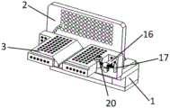
The middle-upper part of the outer side of the vertical plate of the fixing clamp body is provided with a plurality of round holes for installing the fixing rods. The fixing rod 16 is provided with a pressing bolt 17 to fix the workpiece, so that the workpiece can be pressed at any position.
The mounting seat 1 is composed of an upper flat plate 27, an insulator block 28 and a lower flat plate 29, wherein the insulator block is arranged between the upper flat plate and the lower flat plate, and a plurality of threaded holes are formed in the upper flat plate and the lower flat plate. The mounting base 1 is fixed on the working table of the machine tool through a threaded hole by a bolt.
When the rotary worktable 3 is used, the first conical surface positioning pin 9 and the second conical surface positioning pin 11 can slide in respective shaft holes by pulling the first nut 4 and the second nut 5, so that the first conical surface positioning pin 9 is separated from being matched with the positioning conical hole 21 on the fixed fixture body 2, and the second conical surface positioning pin 11 is separated from being matched with the indexing conical hole 23 on the fixed fixture body 2, so that the rotary worktable 3 rotates. Ten indexing taper holes are arranged on the fixed clamp body 2, the pitch of each hole is 5 degrees, the conical surface positioning pin 11 is matched with different taper holes to enable the workbench to obtain different angles, the conical surface positioning pin is matched with a first taper hole to enable the workbench to be in a horizontal position, the conical surface positioning pin is matched with a second taper hole to enable the workbench to be inclined by 5 degrees, the conical surface positioning pin is matched with a third taper hole to enable the workbench to be inclined by 10 degrees, the conical surface positioning pin is matched with a fourth taper hole to enable the workbench to be inclined by 15 degrees, the conical surface positioning pin is matched with a fifth taper hole to enable the workbench to be inclined by 20 degrees, the conical surface positioning pin is matched with a sixth taper hole to enable the workbench to be inclined by 25 degrees, the conical surface positioning pin is matched with a seventh taper hole to enable the workbench to be inclined by 30 degrees, the conical surface positioning pin is matched with an eighth taper hole to enable the workbench to be inclined by 35 degrees, the conical surface positioning pin is matched with a ninth taper hole to enable the workbench to be inclined by, the clamp can clamp cylindrical parts in the horizontal direction or the vertical direction, a fixing rod 16 is placed in a cylindrical hole in the fixing clamp body 2, the fixing rod 16 is in sliding fit with the cylindrical hole, and a pressing bolt 17 is placed on the fixing rod 16 to press a workpiece. Various auxiliary tools can be installed in threaded holes formed in the rotary worktable 3 to clamp workpieces in various shapes, a V-shaped block 15 is installed on the rotary worktable in the schematic diagram of fig. 4 and is used for clamping a workpiece 18 rough boring cutter bar, a V-shaped groove in a horizontal position is formed in the rotary worktable 3 to clamp the workpiece in the schematic diagram of fig. 5, and a V-shaped groove in a vertical position is formed in the rotary worktable 3 to clamp cylindrical parts in the schematic diagram of fig. 6.
The utility model discloses a set up the mount pad, the fixed clamp body, rotate the workstation, solved the difficult processing problem of the too big angle of numerical control wire-electrode cutting, on this anchor clamps, the various clamping of assisting the utensil of configuration can carry out different grade type part.
The foregoing is merely illustrative of some of the principles of the present invention and the description is not intended to limit the invention to the specific constructions and applications shown, so that all modifications and equivalents that may be utilized are within the scope of the invention.
Other technical features than those described in the specification are known to those skilled in the art.
Claims (7)
1. The utility model provides an anchor clamps are used in numerical control wire-electrode cutting processing, characterized by, including the mount pad, the fixation clamp body and swivel work head, the fixation clamp body is L shapes, and the concrete bottom plate of fixation clamp passes through the bolt and is fixed with the mount pad, the outside of the concrete riser of fixation clamp is located to the swivel work head, swivel work head is connected through first conical surface locating pin and second conical surface locating pin with the fixation clamp body, the outside of the concrete riser of fixation clamp is equipped with location taper hole, dead eye and graduation taper hole, the swivel work head passes through the mandrel and is connected with the dead eye rotation, first conical surface locating pin and location taper hole cooperation, second conical surface locating pin and graduation taper hole cooperation.
2. The clamp for numerical control wire-electrode cutting according to claim 1, wherein the rotary table is L-shaped composed of a fixed plate and a workpiece mounting plate, the fixed plate is vertically connected with the workpiece mounting plate, a first shaft hole is arranged at one end of the fixed plate, a second shaft hole is arranged at the middle part of the fixed plate, a third shaft hole is arranged at the other end of the fixed plate, a V-shaped groove for placing the workpiece is respectively arranged at the middle part and the side edge of the upper surface of the workpiece mounting plate, and a threaded hole is respectively arranged at the upper surface and the front side of the workpiece mounting plate.
3. The clamp for numerical control wire-electrode cutting according to claim 2, wherein a V-shaped block is provided on the workpiece mounting plate of the rotary table, and a V-shaped groove for clamping and placing the workpiece is provided on the V-shaped block.
4. The clamp for numerical control wire-electrode cutting according to claim 1, wherein the fixed clamp body is provided with a bearing hole, the sealing bearing is in interference fit with the bearing hole, and the mandrel on the rotary table is in interference fit connection with the sealing bearing on the fixed clamp body through a shaft hole on the rotary table.
5. The clamp for numerical control wire-electrode cutting according to claim 1, wherein the front portion of the first conical positioning pin is a conical surface capable of fitting with the positioning taper hole, the middle portion is a cylindrical surface fitting with the first shaft hole provided on the rotary table, the tail portion is a screw thread, the tail portion of the first conical positioning pin fits with the first nut through the second spring, the front portion of the second conical positioning pin is a conical surface fitting with the indexing taper hole, the middle portion is a cylindrical surface fitting with the third shaft hole provided on the rotary table, and the tail portion of the second conical positioning pin fits with the second nut through the first spring.
6. The clamp for numerical control wire-electrode cutting according to claim 1, wherein a plurality of graduated taper holes are formed at one end of the outer side of the vertical plate of the fixing clamp body, each pitch is 5 degrees, and a plurality of circular holes for mounting the fixing rod are formed at the middle upper portion of the outer side of the vertical plate.
7. The jig for numerical control wire-cut machining according to claim 1, wherein the mounting seat is composed of an upper plate, an insulator block, and a lower plate, the insulator block is provided between the upper plate and the lower plate, and the upper plate and the lower plate are provided with a plurality of screw holes.
Priority Applications (1)
| Application Number | Priority Date | Filing Date | Title |
|---|---|---|---|
| CN201920097645.XU CN211162277U (en) | 2019-01-21 | 2019-01-21 | Clamp for numerical control wire cutting machining |
Applications Claiming Priority (1)
| Application Number | Priority Date | Filing Date | Title |
|---|---|---|---|
| CN201920097645.XU CN211162277U (en) | 2019-01-21 | 2019-01-21 | Clamp for numerical control wire cutting machining |
Publications (1)
| Publication Number | Publication Date |
|---|---|
| CN211162277U true CN211162277U (en) | 2020-08-04 |
Family
ID=71790153
Family Applications (1)
| Application Number | Title | Priority Date | Filing Date |
|---|---|---|---|
| CN201920097645.XU Expired - Fee Related CN211162277U (en) | 2019-01-21 | 2019-01-21 | Clamp for numerical control wire cutting machining |
Country Status (1)
| Country | Link |
|---|---|
| CN (1) | CN211162277U (en) |
-
2019
- 2019-01-21 CN CN201920097645.XU patent/CN211162277U/en not_active Expired - Fee Related
Similar Documents
| Publication | Publication Date | Title |
|---|---|---|
| CN210677777U (en) | Clamping mechanism for rotary workbench | |
| CN108480923B (en) | Method for precisely machining large thin-wall revolving body part | |
| CN203418337U (en) | Fixture suitable for rapid drilling of rope clip | |
| CN212020489U (en) | Centering vice | |
| CN210255284U (en) | Four-axis rotating tool clamp | |
| CN211162277U (en) | Clamp for numerical control wire cutting machining | |
| CN214979366U (en) | Bench drill objective table tool capable of achieving rapid angle positioning | |
| CN211840281U (en) | Rotary type porous drilling machine fixture for thin-wall sleeve part | |
| CN212857881U (en) | Clamp for numerical control boring machine | |
| CN211760986U (en) | Multiaspect multi-angle processes clamping tool fast | |
| CN114536036A (en) | Novel clamp for machining parts of precision machine tool | |
| CN204711287U (en) | Cross recess gear batch machining drilling jig device | |
| CN210524499U (en) | Novel lateral positioning and clamping device | |
| CN210305885U (en) | Double-station drilling clamp | |
| CN213105682U (en) | Tooling clamp of 20-type drilling and milling machine tool | |
| CN219336832U (en) | Mechanical part processing clamping tool | |
| CN110539188A (en) | Novel lateral positioning and clamping device | |
| CN219336850U (en) | Quick fixture capable of realizing self-centering and multi-combination change | |
| CN220825696U (en) | Automatic centering fixture | |
| CN212444206U (en) | Machine tool positioning fixture | |
| CN221184819U (en) | Shower drilling tool | |
| CN219189421U (en) | High-precision positioning device | |
| CN220903009U (en) | Accurate flat tongs clamping | |
| CN219665827U (en) | Quick positioning and clamping tool for boring precise hole | |
| CN213731253U (en) | Fixture tool for four-blade flat cutter |
Legal Events
| Date | Code | Title | Description |
|---|---|---|---|
| GR01 | Patent grant | ||
| GR01 | Patent grant | ||
| CF01 | Termination of patent right due to non-payment of annual fee |
Granted publication date: 20200804 Termination date: 20210121 |
|
| CF01 | Termination of patent right due to non-payment of annual fee |