CN211136437U - Automatic punching device for door and window material processing - Google Patents
Automatic punching device for door and window material processing Download PDFInfo
- Publication number
- CN211136437U CN211136437U CN201921707628.XU CN201921707628U CN211136437U CN 211136437 U CN211136437 U CN 211136437U CN 201921707628 U CN201921707628 U CN 201921707628U CN 211136437 U CN211136437 U CN 211136437U
- Authority
- CN
- China
- Prior art keywords
- clamping
- door
- punching
- plate
- conveying frame
- Prior art date
- Legal status (The legal status is an assumption and is not a legal conclusion. Google has not performed a legal analysis and makes no representation as to the accuracy of the status listed.)
- Expired - Fee Related
Links
Images


Abstract
The utility model relates to the technical field of door and window material production and processing equipment, in particular to an automatic punching device for processing door and window materials, which comprises a feeding material conveying frame, a positioning mechanism, a punching material conveying frame, a clamping mechanism, an adjusting frame, a punching mechanism and a clamping mechanism, wherein the feeding material conveying frame is arranged at the front end of the punching material conveying frame, the upper surfaces of the feeding material conveying frame and the punching material conveying frame are provided with a first slide rail along the processing and conveying direction of the door and window materials, the clamping mechanism is movably arranged on the first slide rail to convey the door and window materials along the first slide rail, the positioning mechanism is arranged on the feeding material conveying frame, the positioning mechanism is used for adjusting the door and window materials to be punched to the position suitable for being clamped by the clamping mechanism to realize the automatic clamping of the door and window materials, the clamping mechanism is arranged on the punching material conveying frame, the clamping mechanism is used for fixing the position of the, the punching mechanism is installed on the adjusting frame.
Description
Technical Field
The utility model relates to a door and window material production and processing equipment technical field, concretely relates to an automatic perforating device for door and window material processing.
Background
The traditional wood door and window material has the defects of high density, high brittleness, short service life, low safety performance and the like, while the traditional metal door and window material has the defects of high safety performance, but the appearance is not large enough, attractive and high cost, so more and more families adopt doors and windows made of alloy materials at present, the metal doors and windows are manufactured by multiple steps of cutting, punching and the like, the traditional punching method is to manually measure and mark a workpiece, and then operating equipment is carried out at the marked position of the raw material; the transmission processing method is low in efficiency and easy to generate errors, so that a plurality of mechanical processing devices are available in the market at present, but most of the devices are used for processing a single door and window material, and some door and window materials can be processed, but the processing precision and efficiency are difficult to guarantee, so that a high-precision and high-efficiency door and window material processing device is needed.
SUMMERY OF THE UTILITY MODEL
In order to solve the problems, the utility model provides an automatic punching device, which comprises a feeding and conveying frame, a positioning mechanism, a punching and conveying frame, a clamping mechanism, an adjusting frame, a punching mechanism and a clamping mechanism, wherein the feeding and conveying frame is arranged at the front end of the punching and conveying frame, the upper surfaces of the feeding and conveying frame and the punching and conveying frame are provided with a first slide rail along the processing and conveying direction of door and window materials, the clamping mechanism is movably arranged on the first slide rail to convey the door and window materials along the first slide rail, the positioning mechanism is arranged on the feeding and conveying frame and is used for adjusting the door and window materials to be punched to a position suitable for being clamped by the clamping mechanism to realize the automatic clamping of the door and window materials, the clamping mechanism is arranged on the punching and conveying frame, the clamping mechanism is used for fixing the position of the door and window material on the punching and conveying frame so as to facilitate punching of the punching mechanism, and the punching mechanism is arranged on the adjusting frame.
The utility model provides an automatic punching device for processing door and window materials, which comprises a feeding material conveying frame, a positioning mechanism, a punching material conveying frame, a clamping mechanism, an adjusting frame, a punching mechanism and a clamping mechanism, wherein the feeding material conveying frame is arranged at the front end of the punching material conveying frame, the upper surfaces of the feeding material conveying frame and the punching material conveying frame are provided with a first slide rail along the processing and conveying direction of the door and window materials, the clamping mechanism is movably arranged on the first slide rail to convey the door and window materials along the first slide rail, the positioning mechanism is arranged on the feeding material conveying frame, the positioning mechanism is used for adjusting the door and window materials to be punched to the position suitable for being clamped by the clamping mechanism to realize the automatic clamping of the door and window materials, the clamping mechanism is arranged on the punching material conveying frame, and the clamping mechanism is used for fixing the position of the door and window materials on the punching material conveying frame so as to punch, the punching mechanism is installed on the adjusting frame.
As a further scheme of an automatic perforating device for door and window materials processing, the alignment jig includes a plurality of adjusting part, and adjusting part movable mounting can be followed on the chassis and moved with door and window materials processing direction of delivery vertically second slide rail by adjusting the actuating mechanism drive on the chassis, is provided with the installation pole parallel with first slide rail on the alignment jig, is provided with the third slide rail along its length direction on the installation pole and evenly is equipped with the actuating lever of a plurality of teeth along length direction with the side, mechanism movable mounting punches is on the third slide rail and is driven along the third slide rail removal by the driving motor who is connected with the actuating lever transmission.
As the utility model relates to an automatic perforating device's for door and window materials processing further scheme, adjust actuating mechanism and install on the chassis, adjust actuating mechanism and include accommodate motor and commutator, accommodate motor is connected with a plurality of commutator transmissions, and the power take off end of commutator passes through ball and is connected with adjusting part to remove adjusting part along second slide rail direction.
As the utility model relates to a further scheme of automatic perforating device for door and window material processing, the mechanism of punching includes mounting panel and the motor that punches, and the mounting panel includes vertical plate and the diaphragm of perpendicular rigid coupling on the vertical plate top, and the mounting panel passes through vertical plate movable mounting on the third slide rail, the motor that punches sets up the opposite side at the vertical plate, the fourth slide rail swing joint of vertical installation on motor and the vertical plate of punching to drive vertical regulation by the lift cylinder of installing on the diaphragm, the power shaft of the motor that punches is vertical and the end installs the drill bit, driving motor install on the diaphragm.
As a further proposal of the automatic punching device for processing the door and window materials, the punching mechanisms are multiple, and the position of each punching mechanism on the third slide rail is controlled and adjusted by a driving motor; the multi-axis machine is installed to punching motor's power shaft end, and the power take off end at the multi-axis machine is installed to a plurality of drill bits, the vertical board bottom rigid coupling of mechanism of punching has the bottom plate, vertically installs a plurality of pressfitting cylinders on the bottom plate.
As a further scheme of the utility model relates to an automatic perforating device for door and window material processing, the holder includes shell, first clamping jaw, second clamping jaw and control cylinder, the shell is the cube bodily form, and the mounting groove that runs through surface about the shell is seted up to the upper surface of shell, first clamping jaw includes first even board and first claw end, and first board sets firmly corresponds mounting groove department and has seted up the through-hole in shell bottom and its face, and first claw end rigid coupling is in the one end of first even board, and the second clamping jaw that is located first clamping jaw below includes second even board and second claw end, is provided with the connecting block on the second even board, and the connecting block passes through-hole on the first even board and through the cell wall swing joint of round pin axle and mounting groove, and second claw end rigid coupling corresponds from top to bottom at the one end of connecting block and with first claw end with the centre gripping door and window material, and window material's other end rigid coupling has L shape's briquetting even, the shell bottom corresponds the notch department and is provided with a piece, and the briquetting is kept away from between the tip of second claw end through spring coupling, and the control cylinder corresponds at the tip at the shell top and puts the control piece with the action.
As a further scheme of the automatic perforating device for door and window materials processing, fixture includes movable plate, centre gripping regulating plate, mounting bracket and holder, and the movable plate is installed on first slide rail, installs the centre gripping driving motor who is used for driving fixture along first slide rail removal regulation on the movable plate, the mounting bracket is installed on the movable plate, and the centre gripping regulating plate is installed on the mounting bracket through the centre gripping cylinder of vertical setting, and the bottom surface of centre gripping regulating plate is provided with a plurality of holders that are used for centre gripping door and window materials, and the direction of arranging of a plurality of holders is parallel with second slide rail length direction.
As a further scheme of the automatic perforating device for door and window material processing, clamping mechanism includes the clamping fixed plate and the clamping fly leaf of quantity such as, and the upper surface level of the defeated work or material rest that punches is equipped with the vaulting pole, and a plurality of clamping fixed plates are fixed on the vaulting pole along the length direction of second slide rail equidistant, and the clamping fly leaf sets up and clamping fly leaf rigid coupling on the regulating plate with clamping fixed plate interval, the regulating plate is connected with the clamping cylinder, and the clamping cylinder is installed on the defeated work or material rest that punches along the length direction of second slide rail to it will treat the door and window material rigidity who punches to drive clamping fly leaf and clamping fixed plate cooperation.
As a further scheme of an automatic perforating device for door and window materials processing, positioning mechanism includes the equal perpendicular rigid coupling of last face has the location fly leaf and the location fixed plate of a plurality of baffles, location fixed plate fixed mounting is on material conveying frame, location fly leaf activity set up on material conveying frame and with the piston rod end-to-end connection of location cylinder, the location cylinder is installed in material conveying frame bottom and along the length direction setting of second slide rail to drive location fly leaf and location fixed plate cooperation will treat that the door and window materials of processing fix a position the position that is fit for the fixture centre gripping.
As a further scheme of the utility model an automatic perforating device for door and window materials processing, the upper surface of material loading and conveying frame is provided with a plurality of rollers along first slide rail direction, and the roller is higher than the top that fixes a position fly leaf and location fixed plate and be less than the baffle.
Advantageous effects
1. The door and window material setting of waiting to punch is driven by fixture to the transport of mechanism department of punching on material conveying frame location back, and fixture carries the door and window material on the material conveying frame of punching and fixed by the clamping, and the mechanism of punching is adjusted including the length direction that can follow first slide rail and second slide rail and is removed, realizes the synchronous high accuracy operation of punching of a plurality of door and window materials, the utility model discloses can make things convenient for the machining efficiency of door and window material greatly, the drive of each direction of the mechanism of punching is servo motor, can guarantee to process required precision.
2. The installation rod is provided with a driving rod, the side surface of the driving rod is provided with teeth along the length direction, the transverse plate of the installation plate is provided with a driving motor, the driving motor is a servo motor, a rotating shaft of the driving motor is provided with a gear, the gear is meshed with the teeth on the side surface of the driving rod, and the relative position of the punching mechanism and a door and window material fixed by clamping can be adjusted with high precision through the driving adjustment of the servo motor; the chassis is provided with a driving mechanism, a regulating motor of the driving mechanism is in transmission connection with the commutator, a power output end of the commutator is connected with the regulating frame through a ball screw, so that the position of the punching mechanism is regulated along the direction of the second slide rail with high precision, the punching mechanism is convenient to correspond to one or more door and window material positions fixed by clamping, and punching operation is realized.
3. The punching mechanism is driven by a driving motor arranged on the mounting plate to adjust along the third slide rail, so that the punching mechanism is driven to punch along the length direction of the door and window material; the adjusting frame is installed on the bottom frame, the bottom frame is movably installed on the bottom frame, the adjusting frame can be adjusted and moved along a second sliding rail perpendicular to the door and window material processing and conveying direction on the bottom frame, and high-precision punching processing can be performed on one or more fixed clamping door and window materials by matching with a punching mechanism capable of moving along the first sliding rail.
Drawings
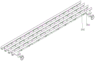
FIG. 1 is a schematic view of the overall structure of the automatic punching apparatus of the present invention;
FIG. 2 is a schematic side view of the automatic punching apparatus of the present invention;
FIG. 3 is a schematic view of an installation structure of a punching mechanism of the automatic punching device of the present invention;
FIG. 4 is a schematic view of the mounting structure of the clamping mechanism of the automatic punching device of the present invention;
FIG. 5 is a schematic side view of the punching mechanism of the automatic punching apparatus of the present invention;
FIG. 6 is a schematic structural view of a clamping mechanism of the automatic punching device of the present invention;
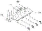
FIG. 7 is a schematic structural view of a clamping mechanism of the automatic punching apparatus of the present invention;
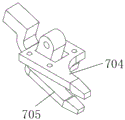
FIG. 8 is a schematic view of an external structure of a clamping member of the clamping mechanism of the automatic punching apparatus of the present invention;
FIG. 9 is a schematic view of the internal structure of the holding member of the holding mechanism of the automatic punching apparatus of the present invention;
the labels in the figure are: 1. the material loading conveying frame, 2, a positioning mechanism, 3, the material loading frame that punches, 4, a clamping mechanism, 5, an adjusting frame, 6, the mechanism that punches, 7, a clamping mechanism, 201, a positioning movable plate, 202, a positioning fixed plate, 401, a clamping fixed plate, 402, a clamping movable plate, 501, a third slide rail, 502, an underframe, 503, an adjusting motor, 504, a commutator, 601, a mounting plate, 602, the motor that punches, 603, a lifting cylinder, 604, a pressing cylinder, 701, a movable plate, 702, a clamping adjusting plate, 703, a mounting frame, 704, a first clamping jaw, 705, a second clamping jaw.
Detailed Description
As shown in the figure: an automatic punching device for processing door and window materials comprises a feeding material conveying frame 1, a positioning mechanism 2, a punching material conveying frame 3, a clamping mechanism 4, an adjusting frame 5, a punching mechanism 6 and a clamping mechanism 7, wherein the feeding material conveying frame 1 is installed at the front end of the punching material conveying frame 3, first slide rails are installed on the upper surfaces of the feeding material conveying frame 1 and the punching material conveying frame 3 along the processing and conveying direction of the door and window materials, the clamping mechanism 7 is movably installed on the first slide rails to convey the door and window materials along the first slide rails, the positioning mechanism 2 is arranged on the feeding material conveying frame 1, the positioning mechanism 2 is used for adjusting the door and window materials to be punched to a position suitable for being clamped by the clamping mechanism 7 to realize automatic clamping of the door and window materials, the clamping mechanism 4 is arranged on the punching material conveying frame 3, the clamping mechanism 4 is used for fixing the door and window materials on the punching material conveying frame 3 so as, the punching mechanism 6 is arranged on the adjusting frame 5.
The adjusting frame 5 comprises a plurality of adjusting components, the adjusting components are movably arranged on the bottom frame 502 and are positioned at the punching conveying frame 3, so that the punching mechanism 6 arranged on the adjusting frame 5 can punch the door and window materials clamped on the punching conveying frame 3, the adjusting components comprise -shaped or I-shaped frame bodies consisting of an upper cross rod, a lower cross rod and an upright post, the adjusting components are arranged along the length direction of a first slide rail and move synchronously, a plurality of parallel second slide rails are arranged on the bottom frame 502 and are vertical to the first slide rail, the adjusting frame 5 is arranged on the bottom frame 502 through the second slide rail, an adjusting driving mechanism for adjusting the position of the adjusting frame 5 along the second slide rail is arranged on the bottom frame 502, the adjusting driving mechanism comprises an adjusting motor 503 and a commutator 504, a plurality of commutators are arranged along the length direction of the first slide rail and correspond to the length direction of the second slide rail, the adjusting components are arranged on the bottom frame 502, the adjusting driving mechanism is connected with the adjusting motor 503 through a screw rod 504, and the adjusting motor 504 is connected with the adjusting mechanism for adjusting the adjusting mechanism through the ball screw rod 503, and the adjusting mechanism is connected with the adjusting motor 504 in the direction;
the clamping mechanism 4 comprises equal numbers of clamping fixed plates 401 and clamping movable plates 402, the scheme is preferably four, a plurality of support rods are arranged on the punching conveying frame 3 along the length direction, the clamping fixed plates 401 are arranged on the conveying surface of the punching conveying frame 3 through the plurality of support rods, the plurality of clamping fixed plates 401 are arranged at equal intervals along the length direction of a second slide rail, each clamping movable plate 402 is correspondingly matched with the clamping fixed plate 401, the plurality of clamping movable plates 402 are arranged on an adjusting plate, the adjusting plate is movably arranged on the punching conveying frame 3 and is connected with the tail end of a piston rod of a clamping cylinder arranged on the punching conveying frame 3, the clamping cylinder is arranged along the length direction of the second slide rail to control the distance between the clamping movable plates 402 and the clamping fixed plates 401 which are matched, so that four door and window materials are clamped and fixed, the punching mechanism 6 can conveniently punch holes, the tops of the clamping fixed plates 401, so as to ensure the clamping effect.
The door window machining device is characterized in that a plurality of adjusting components of the adjusting frame 5 are connected through a mounting rod, the mounting rod is arranged at the top end of each adjusting component and is parallel to a first sliding rail, a third sliding rail 501 and a driving rod are arranged on the mounting rod along the length direction of the mounting rod, teeth are arranged on the side face of the rod body of the driving rod along the length direction of the rod body, a plurality of punching mechanisms 6 are movably mounted on the third sliding rail 501, each punching mechanism 6 comprises a mounting plate 601 and a punching motor 602, the mounting plate 601 comprises a longitudinal plate and a transverse plate which is perpendicularly fixedly connected to the top end of the longitudinal plate, the mounting plate 601 is movably mounted on the third sliding rail 501 through the longitudinal plate, a driving motor is mounted on the transverse plate, the driving motor is vertically mounted on the transverse plate and is provided with a gear, the gear is meshed with the teeth on the side face of the driving rod, the driving motor is used for controlling the mounting mechanism to adjust the position of the punching mechanism 6 along the third sliding rail, the punching motor 602 is arranged on the other side of the longitudinal plate, the punching motor 602 is mounted on the fourth sliding rail which is vertically mounted on the L plate, the longitudinal plate L, the lifting cylinder 603 mounted on the transverse plate, the vertical adjusting mechanism is used for adjusting rack, the sliding rail, the adjusting mechanism, the sliding rail is mounted on the sliding rail, the sliding frame, the sliding rail, the sliding frame is mounted on the sliding frame, the sliding mechanism for adjusting mechanism, the sliding rod, the sliding rail, the sliding rod is mounted on the sliding rod.
The feeding and conveying frame 1 is arranged at one end of the punching and conveying frame 3, a first slide rail is arranged along the feeding and conveying frame 1 and the punching and conveying frame 3, a positioning mechanism 2 and a clamping mechanism 7 are arranged on the feeding and conveying frame 1, the positioning mechanism 2 comprises a positioning movable plate 201 and a positioning fixed plate 202, the upper plate surfaces of which are vertically and fixedly connected with a plurality of baffles, the positioning fixed plate 202 is fixedly arranged on the feeding and conveying frame 1, the positioning movable plate 201 is movably arranged on the feeding and conveying frame 1 and is connected with the tail end of a piston rod of a positioning cylinder, the positioning cylinder is arranged at the bottom of the feeding and conveying frame 1 and is arranged along the length direction of a second slide rail, the number of the positioning movable plates 201 and the number of the positioning fixed plates 202 are four, four door and window materials are respectively placed corresponding to one positioning fixed plate 202 when the feeding is carried out on the feeding and conveying frame 1, and the positioning cylinder is contracted to drive the, the door and window materials at the position respectively correspond to the four clamping parts of the clamping mechanism 7, and the clamping mechanism 7 clamps the four door and window materials and transports the four door and window materials to the punching conveying frame 3 along the length direction of the first sliding rail for punching operation, so that automatic punching processing is realized;
the material loading and conveying frame 1 and the punching and conveying frame 3 are further provided with clamping driving rods, the side faces of the clamping driving rods are provided with teeth, the clamping mechanism 7 comprises a moving plate 701, a clamping adjusting plate 702, a mounting frame 703 and a clamping piece, a clamping driving motor is mounted on the moving plate 701 and is meshed with the teeth of the clamping driving rods through a gear mounted at the tail end of a power shaft of the clamping driving motor, so that the clamping mechanism 7 is driven to move along a first slide rail, the mounting frame 703 is a portal-shaped frame, a clamping cylinder is longitudinally mounted on the mounting frame 703, the clamping adjusting plate 702 is driven to longitudinally adjust through the clamping cylinder, preferably, the clamping adjusting plate 702 is connected with the clamping adjusting plate 702 through two longitudinal plate bodies capable of being adjusted in a staggered mode, so that the height of the clamping adjusting plate 702 can be adjusted in a micro mode and debugging is convenient, the four adjusting pieces are arranged on the bottom face of the clamping adjusting plate 702 at intervals along the length direction of a second slide rail so as to clamp door and window materials, the clamping piece comprises a housing, a first clamping jaw 704, a second clamping jaw 705 and a control cylinder, the housing is cubic, the mounting groove 704 is formed by arranging a first clamping block, the clamping pressing block L, the mounting block is formed by a movable clamping pressing block, the mounting groove is formed by a first clamping block, the mounting groove is formed by a second clamping pressing block, the clamping pressing block is formed by a second clamping pressing block, the clamping block is formed by a second clamping block, the clamping block is fixedly connected with a second clamping block, the clamping block
According to the scheme, when the door and window materials are processed by the operation equipment, at most four door and window materials are arranged corresponding to the positions of the positioning fixing plates 202 respectively, the four positioning movable plates 201 position the four door and window materials to the positions of the positioning fixing plates 202 respectively, the clamping cylinders of the clamping mechanisms 7 drive the four clamping pieces to descend, the clamping driving motors move to enable the end portions of the door and window materials to be located between two clamping jaws of the clamping pieces in an open state, then the two clamping jaws of the clamping pieces are meshed, the clamping cylinders shrink to drive the door and window materials to ascend, then the clamping driving motors move to convey the door and window materials to the designated positions of the punching material conveying frames 3, the clamping cylinders descend to enable the door and window materials to be fixed in position by the clamping mechanisms 4 of the punching material conveying frames 3, the punching mechanisms 6 can complete efficient processing of the door and window materials simultaneously through position adjustment of the punching mechanisms 6 along the third sliding rails 501 and position adjustment of the adjusting frames 5 along the second sliding rails, punching positions of the door and window materials are determined, the punching operations of the door.
The above description is only a preferred embodiment of the present invention, and the present invention is not limited to the above embodiments, and although the present invention has been disclosed with the preferred embodiments, it is not limited to the present invention, and any skilled person in the art can make some modifications or equivalent changes without departing from the technical scope of the present invention.
Claims (10)
1. The utility model provides an automatic perforating device for door and window material processing which characterized in that: the automatic door and window material punching and clamping device comprises a feeding and conveying frame (1), a positioning mechanism (2), a punching and conveying frame (3), a clamping mechanism (4), an adjusting frame (5), a punching mechanism (6) and a clamping mechanism (7), wherein the feeding and conveying frame (1) is installed at the front end of the punching and conveying frame (3), a first sliding rail is installed on the upper surfaces of the feeding and conveying frame (1) and the punching and conveying frame (3) along the processing and conveying direction of door and window materials, the clamping mechanism (7) is movably installed on the first sliding rail to convey the door and window materials along the first sliding rail, the positioning mechanism (2) is arranged on the feeding and conveying frame (1), the positioning mechanism (2) is used for adjusting the door and window materials to be punched to a position suitable for being clamped by the clamping mechanism (7) to realize automatic clamping of the door and window materials, the clamping mechanism (4) is arranged on the punching and conveying frame (3), and the clamping mechanism (4) is used for fixing the door and window materials on the punching and conveying frame (, the punching mechanism (6) is arranged on the adjusting frame (5).
2. The automatic perforating device for processing door and window materials as claimed in claim 1, wherein: the adjusting frame (5) comprises a plurality of adjusting components, the adjusting components are movably mounted on the bottom frame (502) and can be driven by an adjusting driving mechanism to move along a second sliding rail perpendicular to the processing and conveying direction of the door and window materials on the bottom frame (502), an installation rod parallel to the first sliding rail is arranged on the adjusting frame (5), a third sliding rail (501) is arranged on the installation rod along the length direction of the installation rod, a driving rod with a plurality of teeth is uniformly arranged on the side surface of the installation rod along the length direction, and the punching mechanism (6) is movably mounted on the third sliding rail (501) and is driven by a driving motor in transmission connection with the driving rod to move along the third sliding rail (501).
3. The automatic perforating device for processing door and window materials as claimed in claim 2, wherein: the adjusting driving mechanism is installed on the bottom frame (502) and comprises an adjusting motor (503) and a plurality of commutators (504), the adjusting motor (503) is in transmission connection with the commutators (504), and power output ends of the commutators (504) are connected with the adjusting assembly through ball screws so as to move the adjusting assembly along the direction of the second sliding rail.
4. The automatic perforating device for processing door and window materials as claimed in claim 2, wherein: mechanism (6) of punching includes mounting panel (601) and punching motor (602), and mounting panel (601) are including vertical plate and perpendicular rigid coupling at the diaphragm on vertical plate top, and mounting panel (601) are through vertical plate movable mounting on third slide rail (501), punching motor (602) set up at the opposite side of vertical plate, and the fourth slide rail swing joint of vertical installation on punching motor (602) and the vertical plate to drive vertical regulation by lift cylinder (603) of installing on the diaphragm, the power shaft of punching motor (602) is vertical and the end installs the drill bit, driving motor install on the diaphragm.
5. The automatic perforating device for door and window material processing of claim 4, wherein: the number of the punching mechanisms (6) is multiple, and the position of each punching mechanism (6) on the third sliding rail (501) is controlled and adjusted by one driving motor; the multi-shaft machine is installed at the tail end of a power shaft of a punching motor (602), a plurality of drill bits are installed at the power output end of the multi-shaft machine, a bottom plate is fixedly connected to the bottom end of a longitudinal plate of the punching mechanism (6), and a plurality of pressing cylinders (604) are longitudinally installed on the bottom plate.
6. The automatic perforating device for processing door and window materials as claimed in claim 1, wherein: fixture (7) are including movable plate (701), centre gripping regulating plate (702), mounting bracket (703) and holder, and movable plate (701) is installed on first slide rail, installs on movable plate (701) and is used for driving fixture (7) along the centre gripping driving motor of first slide rail removal regulation, mounting bracket (703) are installed on movable plate (701), and centre gripping regulating plate (702) are installed on mounting bracket (703) through the centre gripping cylinder of vertical setting, and the bottom surface of centre gripping regulating plate (702) is provided with a plurality of holders that are used for centre gripping door and window material, and the direction of arranging of a plurality of holders is parallel with second slide rail length direction.
7. The automatic perforating device for door and window material processing as claimed in claim 6, wherein the clamping member comprises a housing, a first clamping jaw (704), a second clamping jaw (705) and a control cylinder, the housing is cube-shaped, the upper surface of the housing is provided with mounting slots penetrating through the upper and lower surfaces of the housing, the first clamping jaw (704) comprises a first connecting plate and a first claw end, the first connecting plate is fixedly arranged at the bottom of the housing, a through hole is formed in the surface of the first connecting plate corresponding to the mounting slots, the first claw end is fixedly connected to one end of the first connecting plate, the second clamping jaw (705) positioned below the first clamping jaw (704) comprises a second connecting plate and a second claw end, the second connecting plate is provided with a connecting block, the connecting block penetrates through the through hole in the first connecting plate and is movably connected with the slot walls of the mounting slots through a pin shaft, the second claw end is fixedly connected to one end of the connecting block and vertically corresponds to the first claw end to clamp the door and window material, the other end of the second connecting plate is fixedly connected to a L-shaped pressing block, the mounting slot is arranged at the bottom of the housing, the mounting slot, the supporting block is connected to the end of the pressing block, and the pressing block, the end of the clamping cylinder.
8. The automatic perforating device for processing door and window materials as claimed in claim 2, wherein: clamping mechanism (4) are including the clamping fixed plate (401) and clamping fly leaf (402) of quantity such as, and the upper surface level of defeated work or material rest (3) punches is equipped with the vaulting pole, and a plurality of clamping fixed plates (401) are fixed on the vaulting pole along the length direction of second slide rail equidistant, and clamping fly leaf (402) and clamping fixed plate (401) interval set up and clamping fly leaf (402) rigid coupling on the regulating plate, the regulating plate is connected with the clamping cylinder, and the clamping cylinder is installed on defeated work or material rest (3) punches along the length direction of second slide rail to drive clamping fly leaf (402) and clamping fixed plate (401) cooperation will treat the door and window material rigidity of punching.
9. The automatic perforating device for processing door and window materials as claimed in claim 2, wherein: positioning mechanism (2) are including last equal perpendicular rigid coupling of face location fly leaf (201) and location fixed plate (202) that have a plurality of baffles, location fixed plate (202) fixed mounting is on material loading and conveying frame (1), location fly leaf (201) activity set up on material loading and conveying frame (1) and with the piston rod end-to-end connection of location cylinder, the location cylinder is installed in material loading and conveying frame (1) bottom and along the length direction setting of second slide rail to drive location fly leaf (201) and location fixed plate (202) cooperation will treat that the door and window material of processing is fixed a position suitable fixture (7) centre gripping.
10. The automatic perforating device for door and window material processing of claim 9, wherein: the upper surface of the feeding and conveying frame (1) is provided with a plurality of rollers along the direction of a first sliding rail, and the rollers are higher than the positioning movable plate (201) and the positioning fixed plate (202) and lower than the top end of the baffle.
Priority Applications (1)
| Application Number | Priority Date | Filing Date | Title |
|---|---|---|---|
| CN201921707628.XU CN211136437U (en) | 2019-10-12 | 2019-10-12 | Automatic punching device for door and window material processing |
Applications Claiming Priority (1)
| Application Number | Priority Date | Filing Date | Title |
|---|---|---|---|
| CN201921707628.XU CN211136437U (en) | 2019-10-12 | 2019-10-12 | Automatic punching device for door and window material processing |
Publications (1)
| Publication Number | Publication Date |
|---|---|
| CN211136437U true CN211136437U (en) | 2020-07-31 |
Family
ID=71766754
Family Applications (1)
| Application Number | Title | Priority Date | Filing Date |
|---|---|---|---|
| CN201921707628.XU Expired - Fee Related CN211136437U (en) | 2019-10-12 | 2019-10-12 | Automatic punching device for door and window material processing |
Country Status (1)
| Country | Link |
|---|---|
| CN (1) | CN211136437U (en) |
Cited By (1)
| Publication number | Priority date | Publication date | Assignee | Title |
|---|---|---|---|---|
| CN112605421A (en) * | 2020-12-02 | 2021-04-06 | 布莱凯特设备(苏州)有限公司 | Plate positioning and drilling system and positioning method |
-
2019
- 2019-10-12 CN CN201921707628.XU patent/CN211136437U/en not_active Expired - Fee Related
Cited By (2)
| Publication number | Priority date | Publication date | Assignee | Title |
|---|---|---|---|---|
| CN112605421A (en) * | 2020-12-02 | 2021-04-06 | 布莱凯特设备(苏州)有限公司 | Plate positioning and drilling system and positioning method |
| CN112605421B (en) * | 2020-12-02 | 2022-02-22 | 布莱凯特设备(苏州)有限公司 | Plate positioning and drilling system and positioning method |
Similar Documents
| Publication | Publication Date | Title |
|---|---|---|
| CN111644834B (en) | Detachable truss screw machine | |
| CN213560005U (en) | Drilling tool for flange | |
| CN112588938A (en) | Punching equipment for processing solar frame | |
| CN211136437U (en) | Automatic punching device for door and window material processing | |
| CN219852708U (en) | Profile panel laser cutting machining tool | |
| CN211135609U (en) | A batch perforating device for door and window material | |
| CN112109212A (en) | Automatic equipment for machining floor bearing plate assembly for pouring reinforced cement | |
| CN211136438U (en) | A material loading clamping device for door and window material processing | |
| CN211136435U (en) | Automatic cutting device for door and window material processing | |
| CN115383176A (en) | Punching equipment for elevator track machining | |
| CN110549123B (en) | Automatic door and window material processing equipment | |
| CN215357163U (en) | Automatic steel rail assembling machine | |
| CN212552618U (en) | Detachable truss screw machine | |
| CN211135610U (en) | Perforating device for door and window materials | |
| CN210818281U (en) | Automatic unloading mechanism of going up of ring gear | |
| CN209868633U (en) | Power starting device for workpiece machining clamp | |
| CN210413376U (en) | Automatic assembling machine for lampshade of electric welding pliers | |
| CN210587315U (en) | Clamping device for multi-spindle drilling machine | |
| CN108838430B (en) | Perforating device suitable for power equipment filter screen | |
| CN108526517B (en) | Perforating device suitable for power equipment filter screen | |
| CN108788229B (en) | Automatic perforating device of filter screen for power equipment | |
| JPS61146435A (en) | Automatic clip setting device | |
| CN218136626U (en) | Material feeding unit is used in CNC processing | |
| CN216881808U (en) | Numerical control drilling equipment | |
| CN214391898U (en) | Precise full-automatic processing device for lock |
Legal Events
| Date | Code | Title | Description |
|---|---|---|---|
| GR01 | Patent grant | ||
| GR01 | Patent grant | ||
| CF01 | Termination of patent right due to non-payment of annual fee | ||
| CF01 | Termination of patent right due to non-payment of annual fee |
Granted publication date: 20200731 Termination date: 20201012 |