CN211136123U - Welding positioner for movable arm products - Google Patents
Welding positioner for movable arm products Download PDFInfo
- Publication number
- CN211136123U CN211136123U CN201921616020.6U CN201921616020U CN211136123U CN 211136123 U CN211136123 U CN 211136123U CN 201921616020 U CN201921616020 U CN 201921616020U CN 211136123 U CN211136123 U CN 211136123U
- Authority
- CN
- China
- Prior art keywords
- support
- movable arm
- driven
- base
- bracket
- Prior art date
- Legal status (The legal status is an assumption and is not a legal conclusion. Google has not performed a legal analysis and makes no representation as to the accuracy of the status listed.)
- Active
Links
Images

Landscapes
- Butt Welding And Welding Of Specific Article (AREA)
Abstract
The utility model relates to a movable arm product welding positioner, which comprises a base, wherein the base is respectively and relatively provided with a driven bracket and a driving bracket, the driving bracket is arranged on the base in a sliding manner, and the driving bracket can linearly and reciprocally slide relative to the driven bracket; all pivotally connected with fixture on driven support and the initiative support, fixture is including sliding the adjustable anchor clamps that set up at driven support or initiative support inboard. The utility model discloses a swing arm class product positioner has promoted the application scope of positioner anchor clamps, can be applicable to swing arm class product, carries out centre gripping location and attitude adjustment to swing arm class product.
Description
Technical Field
The utility model relates to a machining technical field, in particular to mechanical fixture, concretely relates to swing arm class product positioner.
Background
In the fixture tool in the prior art, particularly in a fixture tool for assisting welding, the fixture tool is generally limited and fixed through a relatively arranged fixture, then the fixture for clamping a workpiece to be welded is pushed and displaced to a welding structure through a linear rail for welding, and the posture of the workpiece cannot be adjusted in the machining process.
In view of the above technical problems, the prior patents: the follow-up tool for robot co-welding (patent number: CN 201720703641.2) is used for improving the technical problem. The follow-up tool for robot co-welding comprises a gripper and a support; the support consists of a transverse support and a longitudinal support, the transverse support and the longitudinal support are in cross connection, and two ends of the transverse support and the longitudinal support are fixedly connected with clamps for clamping the small pipe fittings to be welded; the gripper is used for clamping the support and comprises a bidirectional cylinder, clamping plates are connected to two ends of the bidirectional cylinder to form a clamping plate pair, and the bidirectional cylinder drives the clamping plates to open and close to complete actions of clamping the support and loosening the support.
However in the improved prior art, the clamp arranged on the support realizes the fixation of the small pipe fittings, the gripper grabs the support, the gripper and the support are jointly arranged on the auxiliary welding robot, the optional position adjustment can be carried out along with the auxiliary welding robot, and the welding operation of the welding robot is conveniently completed. However, the follow-up tool in the prior art is suitable for clamping and fixing small pipes, and is installed on the welding assisting robot to adjust the position along with the welding assisting robot. And is not suitable for clamping and adjusting the position of a slightly larger workpiece.
Disclosure of Invention
The utility model overcomes prior art's is not enough, provides a swing arm class product positioner, has promoted the application scope of positioner anchor clamps, can be applicable to swing arm class product, carries out centre gripping location and attitude adjustment to swing arm class product.
In order to achieve the above purpose, the utility model adopts the technical scheme that: a welding positioner for movable arm products comprises a base, wherein the base is respectively and oppositely provided with a driven bracket and a driving bracket, the driving bracket is arranged on the base in a sliding manner, and the driving bracket can linearly and reciprocally slide relative to the driven bracket; all pivotally connected with fixture on driven support and the initiative support, fixture is including sliding the adjustable anchor clamps that set up at driven support or initiative support inboard.
In a preferred embodiment of the present invention, the adjustable clamp is further provided with an insertion block inside for relative opening and closing.
In a preferred embodiment of the present invention, the holding mechanism is driven to rotate by a motor provided on the driven bracket or the driving bracket.
In a preferred embodiment of the present invention, the base is provided with a wire track; the wire rail is embedded with a sliding seat in a sliding manner, and the driving support is fixedly arranged on the sliding seat.
The utility model discloses a preferred embodiment, fixture includes the mounting panel of pivotal connection on corresponding motor, set up the own anchor clamps line rail on the mounting panel, the slip is provided with a pair of slider on the anchor clamps line rail, every be provided with at least one adjustable anchor clamps on the slider.
In a preferred embodiment of the present invention, one side of the adjustable clamp is in driving connection with a mounting plate of a corresponding driven bracket or a driving bracket through a lead screw; and the other side of the adjustable clamp is provided with an embedding and inserting block embedded with the movable arm workpiece.
The utility model discloses a preferred embodiment is provided with a plurality of pinhole on base or the linear rail, also be provided with the pinhole on the slide, the locating pin is pegged graft and is gone into behind the pinhole of slide, wear to establish again in one of them pinhole that sets up on base or the linear rail.
According to the embodiment, the welding positioner for the movable arm products has the beneficial effects that:
a clamping mechanism is pivotally connected to a driven support and a driving support, and the clamping mechanisms on the driving support and the driven support are adjusted to clamp the rotating angle of a movable arm workpiece, so that the posture and the displacement angle of the movable arm workpiece are adjusted, and the application range of a positioner clamp is widened.
The movable arm workpiece is clamped by the adjustable clamps arranged on the driving support and the driven support in a sliding mode, and the position of the movable arm and the clamping tightness are adjusted by the displacement of the adjustable clamps on the driving support and the driven support. Still set up pinhole and locating pin, will be provided with the slide of initiative support and carry out spacing fixed with the base.
Drawings
The present invention will be further explained with reference to the drawings and examples;
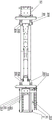
fig. 1 is a schematic structural diagram of a preferred embodiment of the present invention;
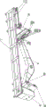
FIG. 2 is a schematic side view of the preferred embodiment of the present invention;
FIG. 3 is a schematic side view of the preferred embodiment of the present invention;
in the figure: 1-base, 11-drag chain, 111-sliding groove, 12-driven bracket, 13-linear rail, 131-pin hole, 2-sliding base, 21-mounting plate, 211-positioning pin, 22-driving bracket, 23-clamping mechanism, 231-adjustable clamp, 232-embedding insert block, 233-clamp linear rail, 234-sliding block, 235-lead screw, 4-movable arm workpiece and 41-clamping groove.
Detailed Description
The invention will now be described in further detail with reference to the accompanying drawings, which are simplified schematic drawings and illustrate, by way of illustration only, the basic structure of the invention, and which therefore show only the constituents relevant to the invention.
As shown in fig. 1 to 3, the welding positioner for the movable arm products comprises a base 1, wherein a driven bracket 12 and a driving bracket 22 are respectively and oppositely arranged on the base 1. One end of the base 1, which is provided with the driving bracket 22, is provided with a wire track 13 which is arranged in parallel; the slide base 2 is slidably embedded on the wire rail 13, and the driving support 22 is fixedly arranged on the slide base 2. One side of the base 1 is slidably provided with a driving bracket 22, and the other side of the base 1 is fixedly provided with a driven bracket 12. The driven bracket 12 and the driving bracket 22 are provided with clamping mechanisms 23 on the inner sides thereof, and the clamping mechanisms 23 on the driven bracket 12 and the driving bracket 22 are respectively connected to the driven bracket 12 and the driving bracket 22 in a pivoting manner. The driven bracket 12 and the driving bracket 22 are provided with motors for driving the clamping mechanism 23 to rotate for angle adjustment, and the motors preferably adopt synchronous motors, so that the postures of the movable arm workpieces 4 can be uniformly adjusted. Here, the driving structure of the motor adopts a driving structure in the prior art, for example, the driving and the limiting braking of the motor are realized through the cooperation of the motor and the braking device, and the specific driving and braking structure and the control method adopt the prior art, and detailed description is omitted here.
In a preferred embodiment of the present invention, as shown in fig. 1 to 3, the driving support 22 is slidably disposed on the parallel linear rails 13 of the base 1, and the driving support 22 can linearly reciprocate relative to the driven support 12; the opposite inner sides of the driving bracket 22 and the driven bracket 12 are pivoted with clamping mechanisms 23. The clamping mechanism 23 comprises a mounting plate 21 pivotally connected with a motor of the driven bracket 12 or the driving bracket 22, a clamp line rail 233 is arranged on the mounting plate 21, a group of sliding blocks 234 are slidably arranged on the clamp line rail 233 on the inner side of the driven bracket 12 or the driving bracket 22, an adjustable clamp 231 capable of moving relatively is arranged on each sliding block 234, and a pair of embedding and inserting blocks 232 capable of opening and closing relatively is further arranged on the inner side of the adjustable clamp 231. Specifically, one end of the adjustable clamp 231 is connected with the corresponding mounting plate 21 of the driven bracket 12 or the driving bracket 22 through the screw rod 235 in a penetrating and screwing manner and then is connected with the slide block 234 in a driving manner; the other end of the adjustable clamp 231 is vertically provided with an embedding and inserting block 232 embedded with the movable arm workpiece 4.
Further, a plurality of pin holes 131 are formed in the base 1 or the line rail 13, the slide base 2 is also provided with the pin holes 131, and the positioning pin 211 is inserted into the pin hole 131 of the slide base 2 and then inserted into one of the pin holes 131 formed in the base 1 or the line rail 13. Further, the utility model discloses in, be provided with linear arrangement's a plurality of pinhole 131 on the linear rail 13, also be provided with pinhole 131 on the slide 2, after the pinhole 131 of slide 2 was pegged graft into to the locating pin 211, wear to establish again in one of them pinhole 131 that set up on the linear rail 13.
In a preferred embodiment of the present invention, as shown in fig. 1 to fig. 3, a sliding groove 111 parallel to one side of the driving support 22 is provided, a drag chain 11 is provided in the sliding groove 111, one end of the drag chain 11 is fixed on the sliding seat 111, the other end of the drag chain 11 is connected to the driving support 22, the drag chain 11 accommodates the cable of the circuit therein, and the driving support 22 is prevented from clamping the cable in the moving process to cause a safety hazard.
The utility model discloses a theory of operation:
as shown in fig. 1 to 3, according to the size adjustment of the boom workpiece 4, the driving bracket 22 is locked on the linear rail 13 of the base 1 by adjusting the driving bracket 22 and the driven bracket 12 on both sides of the base 1 through the positioning pin 211.
The adjustable clamp mechanisms 23 arranged on the driven bracket 12 and the driving bracket 22 are respectively clamped with the clamping grooves 41 at two ends of the movable arm workpiece 4 correspondingly, the scarf insertion blocks 232 on the two pairs of adjustable clamp mechanisms 231 at two ends of the movable arm workpiece 4 are relatively embedded into the clamping grooves 41, the movable arm workpiece 4 is clamped, the clamping tightness is adjusted through adjusting the screw rods 235 connected with the adjustable clamp mechanisms 231 on the driven bracket 12 and the driving bracket 22 until two ends of the movable arm workpiece 4 are locked on the clamping mechanisms 23 arranged on the driven bracket 12 and the driving bracket 22, and the clamping position of the movable arm workpiece 4 is adjusted through adjusting the positions of the clamping mechanisms 23 at two sides on the clamp wire rails 233.
The synchronous motors arranged on the driving support 22 and the driven support 12 synchronously rotate to synchronously adjust the angles of the clamping mechanisms 23 on the driving support 22 and the driven support 12, so that the posture and the deflection angle of the movable arm workpiece 4 are adjusted.
In light of the foregoing, it is to be understood that various changes and modifications may be made by those skilled in the art without departing from the spirit and scope of the invention. The technical scope of the present invention is not limited to the content of the specification, and must be determined according to the scope of the claims.
Claims (7)
1. The utility model provides a movable arm class product positioner, includes base (1), be provided with relative driven support (12) and initiative support (22) on base (1), its characterized in that: the driving support (22) is arranged on the base (1) in a sliding mode, and the driving support (22) can linearly slide in a reciprocating mode relative to the driven support (12); all pivotally connected with fixture (23) on driven support (12) and drive support (22), fixture (23) are including sliding adjustable anchor clamps (231) of setting in driven support (12) or drive support (22) inboard.
2. The welding positioner for movable arm products according to claim 1, characterized in that: the inner side of the adjustable clamp (231) is also provided with a pair of scarf joint insertion blocks (232) which can relatively open and close.
3. The welding positioner for movable arm products according to claim 1, characterized in that: the clamping mechanism (23) is driven to rotate by a motor arranged on the driven bracket (12) or the driving bracket (22).
4. The welding positioner for movable arm products according to claim 1 or 3, characterized in that: a linear rail (13) is arranged on the base (1); the wire rail (13) is slidably embedded with a sliding seat (2), and the driving support (22) is fixedly arranged on the sliding seat (2).
5. The welding positioner for movable arm products according to claim 3, characterized in that: fixture (23) including pivotal connection correspond mounting panel (21) on the motor, be provided with anchor clamps line rail (233) on mounting panel (21), it is provided with a pair of slider (234) to slide on anchor clamps line rail (233), every be provided with at least one adjustable anchor clamps (231) on slider (234).
6. The welding positioner for movable arm products according to claim 5, characterized in that: one side of the adjustable clamp (231) is in driving connection with a corresponding driven bracket (12) or a mounting plate (21) of the driving bracket (22) through a lead screw (235); the other side of the adjustable clamp (231) is provided with an embedding and inserting block (232) embedded with the movable arm workpiece (4).
7. The welding positioner for movable arm products according to claim 4, characterized in that: the wire guide rail is characterized in that a plurality of pin holes (131) are formed in the base (1) or the wire rail (13), pin holes (131) are also formed in the sliding seat (2), and the positioning pins (211) are inserted into the pin holes (131) of the sliding seat (2) and then penetrate into one of the pin holes (131) formed in the base (1) or the wire rail (13).
Priority Applications (1)
| Application Number | Priority Date | Filing Date | Title |
|---|---|---|---|
| CN201921616020.6U CN211136123U (en) | 2019-09-26 | 2019-09-26 | Welding positioner for movable arm products |
Applications Claiming Priority (1)
| Application Number | Priority Date | Filing Date | Title |
|---|---|---|---|
| CN201921616020.6U CN211136123U (en) | 2019-09-26 | 2019-09-26 | Welding positioner for movable arm products |
Publications (1)
| Publication Number | Publication Date |
|---|---|
| CN211136123U true CN211136123U (en) | 2020-07-31 |
Family
ID=71767525
Family Applications (1)
| Application Number | Title | Priority Date | Filing Date |
|---|---|---|---|
| CN201921616020.6U Active CN211136123U (en) | 2019-09-26 | 2019-09-26 | Welding positioner for movable arm products |
Country Status (1)
| Country | Link |
|---|---|
| CN (1) | CN211136123U (en) |
-
2019
- 2019-09-26 CN CN201921616020.6U patent/CN211136123U/en active Active
Similar Documents
| Publication | Publication Date | Title |
|---|---|---|
| CN111002071B (en) | Elbow surface inclined hole machining and positioning device | |
| CN110508889A (en) | A kind of Electric Discharge Machining clamping device special | |
| CN110154075A (en) | Flatly moving type mechanical paw and operating method based on Double-gear | |
| CN113783074B (en) | Full-automatic double-end peeling welding machine for data lines | |
| CN211136123U (en) | Welding positioner for movable arm products | |
| CN106035051B (en) | Gripper for kelp seeding seedlings plugging device | |
| CN206153805U (en) | Shaped steel spare welding flexible clamp and positioning adjustment clamping mechanism thereof | |
| CN205045475U (en) | Soft sackholder utensil of rotation type | |
| CN207435348U (en) | Suitable for the robot clipping machine of detonator production | |
| CN212150735U (en) | Centering rectangular workpiece clamp | |
| CN209157483U (en) | A kind of laser 3D solid welding fixture | |
| CN208385809U (en) | A kind of intelligence harness welder | |
| CN216098996U (en) | Variable-pitch screw positioning and tightening gripper | |
| CN214444088U (en) | Full-automatic mechanical arm with limit structure | |
| CN108723844A (en) | A kind of leaf spring numerical control boring equipment and special fixture | |
| CN213764988U (en) | Compressor anchor clamps | |
| CN109716948B (en) | Grafting stock processing system | |
| CN210360436U (en) | Clamping mechanism | |
| CN114852669A (en) | Upper and lower clamping mechanism | |
| CN209520500U (en) | Automatic welding device | |
| CN210550577U (en) | Servo clamping device | |
| CN207858385U (en) | A kind of multi-station clamp for processing tap three-way connection | |
| CN108687842A (en) | Cutter device for flexible pipe | |
| CN208438234U (en) | High-precision positioning fixture is used in a kind of processing of building materials | |
| CN203527529U (en) | Material tube clamping arm device |
Legal Events
| Date | Code | Title | Description |
|---|---|---|---|
| GR01 | Patent grant | ||
| GR01 | Patent grant |