CN211072830U - Four-axis machining center - Google Patents
Four-axis machining center Download PDFInfo
- Publication number
- CN211072830U CN211072830U CN201921774350.8U CN201921774350U CN211072830U CN 211072830 U CN211072830 U CN 211072830U CN 201921774350 U CN201921774350 U CN 201921774350U CN 211072830 U CN211072830 U CN 211072830U
- Authority
- CN
- China
- Prior art keywords
- axis
- machining
- base
- moving unit
- direction moving
- Prior art date
- Legal status (The legal status is an assumption and is not a legal conclusion. Google has not performed a legal analysis and makes no representation as to the accuracy of the status listed.)
- Active
Links
Images


Abstract
The application discloses four-axis machining center. The four-axis machining center comprises a base, a machining rotary table for machining a workpiece and a protective device, and is characterized in that a base for placing the machining rotary table is fixed on the base, the protective device comprises a movable door and a protective cover, the movable door is installed on a support fixed to the upper portion of the base, a dustproof supporting tube is further arranged on the support, the upper portion of the protective cover is supported by the dustproof supporting tube, and the lower portion of the protective cover is located on the lower portion of the support; the number of the processing rotary tables is at least 2; the four-axis machining center further comprises a main shaft unit, wherein the main shaft unit comprises an X-direction moving unit, a Y-direction moving unit and a Z-direction moving unit, the X-direction moving unit is arranged on the support, and the Y-direction moving unit and the Z-direction moving unit are arranged on the machining rotary table. The technical problem of machining efficiency is low because the inconvenient use causes in the metal working process has been solved in this application.
Description
Technical Field
The application relates to the technical field of metal processing, in particular to a four-axis machining center.
Background
Many enterprises need to use various metal appliances, and most metal appliances can not directly be used, need carry out processing, can effectively use through the machinery after processing, consequently very big to the machining demand.
Present processing machinery is very many, then mechanical processing machinery structure when using, and processing can only process a work piece at every turn to need the manual work to carry out the various work pieces of manual operation, very inconvenient, wasted a large amount of manpowers, reduced production efficiency, the discarded object of a lot of machinery production in the course of working flies in disorder moreover, causes the damage to the people easily, and is very inconvenient to the inside clearance of processing machinery in addition, and then has reduced production efficiency. Aiming at the problem of low efficiency of a processing machine in the processing process, an effective solution is not provided at present.
SUMMERY OF THE UTILITY MODEL
The main aim at of this application provides a duplex position four-axis machining center to solve the technical problem that efficiency is low in the course of working.
In order to achieve the above object, according to one aspect of the present application, a four-axis machining center is provided. This duplex position four-axis machining center includes: the device comprises a base, a processing turntable and a protection device; the protective cover mainly prevents some wastes in the processing process from splashing, the base is fixed on the ground, and the processing rotary table mainly processes the metal to be processed.
A base for placing a processing rotary table is fixed on the base, and the processing rotary table is placed on the base; the protective device comprises a movable door and a protective cover, the movable door is arranged around a support fixed on the upper part of the base, a dustproof supporting tube is further arranged on the support, the upper part of the protective cover is supported by the dustproof supporting tube, and the lower part of the protective cover is positioned on the lower part of the support; the number of the processing rotary tables is at least 2, and the processing rotary tables process and turn over workpieces. The workpiece fixing device is characterized in that a first fixing device used for fixing a workpiece is further arranged on the support, the direction of the first fixing device is X-direction, namely the first fixing device is transversely arranged, the first fixing device is located at the lower end of the support, a clamp is arranged in the first fixing device, and the clamp is mainly used for fixing a workpiece. Simultaneously, the first fixing device is provided with a rotating shaft, can turn 360 degrees, is convenient to machine the upper direction and the lower direction of the machined part, can machine different angles, and is more convenient to machine than the fixed direction of the traditional fixed machined part.
The four-axis machining center further comprises a main shaft unit, wherein the main shaft unit comprises an X-direction moving unit, a Y-direction moving unit and a Z-direction moving unit, the X-direction moving unit is arranged on the support, and the Y-direction moving unit and the Z-direction moving unit are arranged on the machining rotary table. The X-direction moving unit is in the transverse direction, the Y-direction moving unit is in the longitudinal direction, and the Z-direction moving unit is in the height direction. This four-axis machining center has operation platform, places on the processing changes the machine or on the support, makes the processing change the machine through operation platform and removes the back along X, Y, Z directions, and the motor provides power, changes the tool magazine on the machine through the processing and processes. The upper part of the bracket and the left side, the right side and the rear side of the bracket are all provided with baffles for blocking scraps generated by processing.
Furthermore, the support is of a frame structure consisting of a plurality of square pipes. The frame structure has larger internal space, and can more conveniently operate the machining centers at the periphery.
The movable door is characterized in that a movable door guide rail and a motor for controlling the movable door are arranged on the upper part of the bracket, the movable door is L-shaped and is arranged on one part of the front side and the upper side of the bracket, and when the movable door is controlled by the motor, the movable door moves left and right through the movable door guide rail.
Further, a coupler, a motor, a section bar machine base and a tool magazine are arranged on the processing rotary table, the section bar machine base is arranged at the bottom of the processing rotary table, and the section bar machine base is arranged on the base.
Furthermore, the Z-direction movement unit on the processing rotary table comprises a Z-axis screw rod, a Z-axis guide rail and a bearing seat at the lower end of the Z-axis screw rod, the Z-direction movement unit controls the direction perpendicular to the base, the tool magazine moves up and down along the Z-axis screw rod, and a motor on the processing rotary table drives the tool magazine to process the workpiece. The number of the Z-axis guide rails and the number of the Z-axis lead screws are at least 2.
Furthermore, the Y-direction movement unit on the processing rotary table comprises a Y-axis guide rail and a Y-axis screw rod, the Y-axis guide rail is installed on the section bar machine base, bearing seats are installed at two ends of the Y-axis screw rod, and the Y-axis screw rod is in a longitudinal direction.
Furthermore, the X-direction movement unit comprises an X-axis guide rail, the X-axis guide rail is transverse, and the machining rotary table moves transversely through the X-axis guide rail.
Furthermore, a shock pad is installed on the support.
Further, a collecting device for collecting waste materials is also arranged on the base. The collecting device is mainly used for collecting the generated metal waste, so that the metal waste can be treated more quickly and better, the labor force is reduced, and the time is saved. The collecting device for collecting waste materials further comprises a conveyor belt and a collecting box, wherein the conveyor belt is located at the lower portion of the processing rotary table, and materials such as scraps of the processed parts are moved through the conveyor belt and collected in the collecting box, so that the processing is facilitated. The periphery processing center is also provided with a control device for controlling the processing rotary table, and the control device controls the processing rotary table, the movable door and the collecting device.
Furthermore, the lower part of the processing rotary table is also provided with a screw rod seat, a through hole is formed in the screw rod seat, and the Y-axis screw rod penetrates through the through hole in the screw rod seat. The number of Y-axis screw rods is at least 2.
In this application, the processing revolving stage of adoption passes through the motor and removes, and support and protection casing, floating gate in addition on the four-axis processing center, process the metal work piece that will process through motor drive tool magazine to adopt processing revolving stage more than 2 to process, improved production efficiency, reached the purpose of high-efficient production, thereby realized the technological effect of processing machinery high-efficient production among the metal machining, and then solved because the inconvenient technical problem that machining efficiency is low that causes of use among the metal machining process.
Drawings
The accompanying drawings, which are incorporated in and constitute a part of this application, serve to provide a further understanding of the application and to enable other features, objects, and advantages of the application to be more apparent. The drawings and their description illustrate the embodiments of the invention and do not limit it. In the drawings:
FIG. 1 is a block diagram of a four-axis machining center according to the present application;
fig. 2 is a structural view of a machining turntable of a four-axis machining center according to an embodiment of the present application;
fig. 3 is a structural view of a first fixing device of a four-axis machining center according to an embodiment of the present application;
fig. 4 is a structural view of a movable door of a four-axis machining center according to an embodiment of the present application;
fig. 5 is a structural view of a collecting device of a four-axis machining center according to an embodiment of the present application.
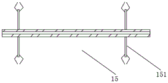
Wherein the figures show: 1. a base; 2. a base; 3. processing the rotary table; 31. a coupling; 32. a section bar base; 33. a tool magazine; 331. a tool magazine support; 34. processing the main body; 4. a support; 51. a movable door; 511. a moving door guide rail; 52. a protective cover; 53. a dustproof supporting tube; 71. X-axis guide rails; a Y-axis guide rail; 82. Y-axis lead screw; a Z-axis lead screw; 92. Z-axis guide rails; 10. a shock pad; 11. a collection device; 12. a screw base; 13. a bearing seat; 14. a motor; 15. a first fixing device; 151. a clamp; 111. a conveyor belt; 112. and (4) collecting the box.
Detailed Description
In order to make the technical solutions better understood by those skilled in the art, the technical solutions in the embodiments of the present application will be clearly and completely described below with reference to the drawings in the embodiments of the present application, and it is obvious that the described embodiments are only partial embodiments of the present application, but not all embodiments. All other embodiments, which can be derived by a person skilled in the art from the embodiments given herein without making any creative effort, shall fall within the protection scope of the present application.
It is noted that the terms used in the description and claims of the present application and the accompanying drawings described above are used for distinguishing between similar elements and not necessarily for describing a particular sequential or chronological order. It should be understood that the data so used may be interchanged under appropriate circumstances such that embodiments of the application described herein may be used. Furthermore, the terms "comprises," "comprising," and "having," and any variations thereof, are intended to cover a non-exclusive inclusion, such that a process, method, system, article, or apparatus that comprises a list of steps or elements is not necessarily limited to those steps or elements expressly listed, but may include other steps or elements not expressly listed or inherent to such process, method, article, or apparatus.
In this application, the terms "upper", "lower", "left", "right", "top", "bottom", "horizontal", "lateral", "longitudinal", and the like indicate orientations or positional relationships based on the orientations or positional relationships shown in the drawings. These terms are used primarily to better describe the present application and its embodiments, and are not used to limit the indicated devices, elements or components to a particular orientation or to be constructed and operated in a particular orientation.
Moreover, some of the above terms may be used to indicate other meanings besides the orientation or positional relationship, for example, the term "on" may also be used to indicate some kind of attachment or connection relationship in some cases. The specific meaning of these terms in this application will be understood by those of ordinary skill in the art as appropriate.
Furthermore, the terms "mounted," "disposed," "provided," and "connected" are to be construed broadly. For example, it may be a fixed connection, a removable connection, or a unitary construction; can be a mechanical connection, or an electrical connection; may be directly connected, or indirectly connected through intervening media, or may be in internal communication between two devices, elements or components. The specific meaning of the above terms in the present application can be understood by those of ordinary skill in the art as appropriate.
It should be noted that the embodiments and features of the embodiments in the present application may be combined with each other without conflict. The present application will be described in detail below with reference to the embodiments with reference to the attached drawings.
As shown in fig. 1-5, the present application relates to a peripheral machining center comprising: the device comprises a base 1, a processing turntable 3 and a protection device; the protective cover 52 mainly prevents some wastes in the processing process from splashing, the base 1 is placed on the ground to be fixed, and the processing rotary table 3 mainly processes the metal to be processed.
As shown in fig. 1-5, a base 2 for placing a processing turntable 3 is arranged on a base 1, the base 2 is fixedly connected with the base 1, and the processing turntable 3 is placed on the base 2; a support 4 is arranged above the base 1, the protection device comprises a movable door 51 and a protection cover 52, the movable door 51 is arranged around the support 4, a dustproof support pipe 53 is also arranged on the support 4, the upper part of the protection cover 52 is placed on the dustproof support pipe 53, and the lower part of the protection cover 52 is placed on the lower support 4; the number of the processing rotary table 3 is 2, and the processing rotary table 3 processes and overturns the workpiece. The support 4 is further provided with a first fixing device 15 for fixing the workpiece, the direction of the first fixing device is an X direction, namely the first fixing device is transversely arranged, a clamp 151 is arranged in the first fixing device 15, and the clamp 151 is mainly used for fixing the workpiece. Meanwhile, the first fixing device is provided with a rotating shaft, can turn 360 degrees, is convenient to machine the upper direction and the lower direction of a machined part, can machine different angles, and is more convenient to machine than the traditional fixed machined part in one fixed direction.
As shown in fig. 1 to 5, the four-axis machining center further includes a spindle unit including an X-direction moving unit, a Y-direction moving unit, and a Z-direction moving unit, the X-direction moving unit being disposed on the support 4, and the Y-direction moving unit and the Z-direction moving unit being disposed on the machining turret 3. The X-direction moving unit is in the transverse direction, the Y-direction moving unit is in the longitudinal direction, and the Z-direction moving unit is in the height direction. This four-axis machining center has operation platform, places on processing changes the machine or on support 4, makes processing change the machine through operation platform and removes along X, Y, Z directions after, and motor 14 provides power, changes the tool magazine on the machine through processing and processes. The upper part of the bracket 4 and the left side, the right side and the rear side of the bracket 4 are all provided with baffles for blocking scraps generated by processing. The baffle can be made of stainless steel.
As shown in fig. 1-5, the support 4 has a frame structure consisting of a plurality of square pipes, the frame structure has a larger internal space and can more conveniently operate a peripheral machining center, the support 4 is provided with a movable door guide 511 and a motor 14 for controlling the movable door 51, the motor 14 drives the movable door to move through an adhesive tape, the support 4 is provided with a shock pad 10, the movable door guide 511 and the motor 14 for controlling the movable door are both arranged on the upper part of the support, the movable door is L-shaped and arranged on a part of the front side and the upper side of the support, and when the movable door is controlled through the motor, the movable door moves left and right through the movable door guide.
As shown in fig. 1-5, the processing turret 3 is provided with a coupling 31, a motor 14, a profile machine base 32 and a tool magazine 33, the profile machine base 32 is arranged at the bottom of the processing turret 3, and the profile machine base 32 is arranged on the base 2. The processing turret 3 is also provided with a tool magazine support 331.
As shown in fig. 1 to 5, the Z-direction moving unit on the processing turntable 3 includes a Z-axis lead screw 91, a Z-axis guide rail 92, and a bearing seat 13 at the lower end of the Z-axis lead screw 91, the Z-direction moving unit controls the direction perpendicular to the base 2, the tool magazine 33 moves along the Z-axis lead screw 91, and the motor on the processing turntable 3 operates to drive the tool magazine 33 to process the workpiece. The Y-direction moving unit on the processing rotary table 3 comprises a Y-axis guide rail 81 and a Y-axis screw rod 82, the Y-axis guide rail 81 is installed on the section bar machine base 32, bearing seats 13 are installed at two ends of the Y-axis screw rod 82, and the direction of the Y-axis screw rod 82 is longitudinal. The lower part of the processing turntable 3 is also provided with a screw rod seat 12, a through hole is arranged in the screw rod seat 12, and the Y-axis screw rod 82 penetrates through the through hole in the screw rod seat 12.
As shown in fig. 1 to 5, the X-direction moving unit includes an X-axis guide 71, the X-axis guide 71 is in a transverse direction, and the processing turret 3 is moved in the transverse direction by the X-axis guide 71. The number of the Z-axis guide rail, the number of the Z-axis screw rod, the number of the Y-axis guide rail and the number of the Y-axis screw rod are 2 on each processing turntable.
As shown in fig. 1-5, the base 1 is also provided with a collection device 11 for collecting waste material. The collecting device 11 is mainly used for collecting the generated metal waste, so that the metal waste can be treated more quickly and better, the labor force is reduced, and the time is saved. The waste collecting device 11 further comprises a conveyor belt 111 and a collecting box 112, wherein the conveyor belt is located at the lower part of the processing rotary table, and the conveyor belt moves the materials such as the scraps of the processing pieces and collects the materials into the collecting box for convenient disposal. The periphery processing center is also provided with a control device for controlling the processing rotary table, and the control device controls the processing rotary table, the movable door and the collecting device.
In this embodiment, the machining turntable 3 that is adopted moves through the motor 14, still have support 4 and protection casing 52 in the four-axis machining center, floating gate 51 is on support 4, the machining turntable 3 moves about through X axle guide rail 71, the processing main part 34 on the machining turntable 3 moves through Y axle guide rail 81 fore-and-aft direction, the tool magazine on the machining turntable 3 moves through Z axle guide rail 92 upper and lower direction, the metal work piece that will process is processed through motor drive tool magazine, and adopt 2 machining turntables 3 to process, production efficiency is improved, the purpose of high-efficient production has been reached, thereby the technological effect of machining machine tool high-efficient production in the metalworking has been realized, and then the technical problem that machining efficiency is low because inconvenient the operation causes in the metalworking process has been solved.
The above description is only a preferred embodiment of the present application and is not intended to limit the present application, and various modifications and changes may be made by those skilled in the art. Any modification, equivalent replacement, improvement and the like made within the spirit and principle of the present application shall be included in the protection scope of the present application.
Claims (10)
1. A four-axis machining center comprises a base (1), a machining rotary table (3) for machining a workpiece and a protection device, and is characterized in that a base (2) for placing the machining rotary table (3) is fixed on the base (1), and the machining rotary table (3) is arranged on the base (2); the protective device comprises a movable door (51) and a protective cover (52), the movable door (51) is mounted on a support (4) fixed on the upper part of the base, a dustproof support pipe (53) is further arranged on the support (4), the upper part of the protective cover (52) is supported by the dustproof support pipe (53), and the lower part of the protective cover (52) is located at the lower part of the support (4); the number of the processing rotary tables (3) is at least 2; the four-axis machining center further comprises a main shaft unit, wherein the main shaft unit comprises an X-direction moving unit, a Y-direction moving unit and a Z-direction moving unit, the X-direction moving unit is arranged on the support (4), and the Y-direction moving unit and the Z-direction moving unit are arranged on the machining rotary table (3).
2. Four-axis machining center according to claim 1, characterized in that the support (4) is a frame structure consisting of a plurality of square tubes.
3. Four-axis machining center according to claim 1, characterized in that on the carriage (4) are mounted a moving door guide (511) and a motor (14) controlling the moving door (51).
4. Four-axis machining center according to claim 1, characterized in that said machining turret (3) is provided with a coupling (31), a motor, a profile stand (32) and a tool magazine (33), said profile stand (32) being at the bottom of the machining turret (3), said profile stand (32) being seated on a base (2).
5. The four-axis machining center according to claim 4, wherein the Z-direction moving unit on the machining turntable (3) comprises a Z-axis screw (91), a Z-axis guide rail (92) and a bearing seat (13) at the lower end of the Z-axis screw (91), the Z-direction moving unit controls the direction perpendicular to the base (2), and the tool magazine (33) moves up and down along the Z-axis screw (91).
6. Four-axis machining center according to claim 4, characterized in that the Y-direction moving unit on the machining turntable (3) comprises a Y-axis guide rail (81) and a Y-axis screw (82), the Y-axis guide rail (81) is mounted on the profile machine base (32), bearing seats (13) are mounted at two ends of the Y-axis screw (82), and the direction of the Y-axis screw (82) is longitudinal.
7. Four-axis machining center according to claim 1, characterized in that the X-direction movement unit comprises an X-axis guide (71), the X-axis guide (71) being oriented in the transverse direction, the machining turret (3) being moved in the transverse direction by means of the X-axis guide (71).
8. Four-axis machining center according to claim 1, characterized in that shock absorbing pads (10) are mounted on the carriage (4).
9. Four-axis machining center according to claim 1, characterized in that on the base (1) there is also mounted a collection device (11) for collecting the scraps.
10. Four-axis machining center according to claim 6, characterized in that the machining turret (3) has a screw base (12) at the lower part, the screw base (12) has a through hole therein, and the Y-axis screw (82) passes through the through hole in the screw base (12).
Priority Applications (1)
| Application Number | Priority Date | Filing Date | Title |
|---|---|---|---|
| CN201921774350.8U CN211072830U (en) | 2019-10-22 | 2019-10-22 | Four-axis machining center |
Applications Claiming Priority (1)
| Application Number | Priority Date | Filing Date | Title |
|---|---|---|---|
| CN201921774350.8U CN211072830U (en) | 2019-10-22 | 2019-10-22 | Four-axis machining center |
Publications (1)
| Publication Number | Publication Date |
|---|---|
| CN211072830U true CN211072830U (en) | 2020-07-24 |
Family
ID=71641261
Family Applications (1)
| Application Number | Title | Priority Date | Filing Date |
|---|---|---|---|
| CN201921774350.8U Active CN211072830U (en) | 2019-10-22 | 2019-10-22 | Four-axis machining center |
Country Status (1)
| Country | Link |
|---|---|
| CN (1) | CN211072830U (en) |
Cited By (1)
| Publication number | Priority date | Publication date | Assignee | Title |
|---|---|---|---|---|
| CN110576333A (en) * | 2019-10-22 | 2019-12-17 | 意特利(滁州)智能数控科技有限公司 | Four-axis machining center |
-
2019
- 2019-10-22 CN CN201921774350.8U patent/CN211072830U/en active Active
Cited By (1)
| Publication number | Priority date | Publication date | Assignee | Title |
|---|---|---|---|---|
| CN110576333A (en) * | 2019-10-22 | 2019-12-17 | 意特利(滁州)智能数控科技有限公司 | Four-axis machining center |
Similar Documents
| Publication | Publication Date | Title |
|---|---|---|
| CN211028239U (en) | Numerical control milling machine | |
| CN211072830U (en) | Four-axis machining center | |
| CN210255406U (en) | Numerical control cutting machine for furniture processing | |
| CN110576333A (en) | Four-axis machining center | |
| CN217096590U (en) | Automatic tool changing and perforating equipment | |
| CN212794073U (en) | Numerical control machine tool convenient for fixing workpiece | |
| CN205342104U (en) | Full -automatic spiral bevel gear cutting machine | |
| CN209972017U (en) | Numerical control engraving and milling machine with manipulator | |
| CN209969882U (en) | Cutting equipment with prevent fish tail function | |
| CN210968152U (en) | Automatic device for grinding silicon rod plane and chamfer | |
| CN111992819A (en) | Chamfering device for gear production | |
| CN212664953U (en) | Drilling equipment is used in valve processing | |
| CN217750490U (en) | Built-in automatic positioning's five automatic feeder equipment of bull towards five axles of planer-type | |
| CN219725465U (en) | Dustproof cutting device | |
| CN212734158U (en) | Vertical lathe driven by linear motor | |
| CN220240210U (en) | Burr removing device | |
| CN216096435U (en) | Lathe hydraulic equipment with safety protection function | |
| CN210731835U (en) | Lathe with slag removal device | |
| CN211102729U (en) | CNC is workstation for digit control machine tool | |
| CN107984282A (en) | A kind of circular tool magazine and cutter changing system and its replacing options | |
| CN113997173B (en) | Flexible inner wall floating polishing table | |
| CN108098368A (en) | Line-controlled robot people | |
| CN214212949U (en) | Horizontal three-coordinate numerical control equipment | |
| CN217493364U (en) | Numerical control drilling, tapping and milling integrated machine | |
| CN220279057U (en) | Carving mills machine with dust absorption function |
Legal Events
| Date | Code | Title | Description |
|---|---|---|---|
| GR01 | Patent grant | ||
| GR01 | Patent grant |