Automatic slurry tank for manganese-zinc ferrite material
Technical Field
The utility model relates to a manganese zinc ferrite material production facility field especially relates to a manganese zinc ferrite material is with automatic thick liquid pond.
Background
With the gradual implementation of the national policy of energy conservation and environmental protection, enterprises and manufacturers for producing manganese-zinc ferrite in China actively improve the environmental factors influencing dust, noise, pollution and the like, and simultaneously continuously improve the automation degree of production equipment and reduce the labor intensity of workers. Improving the labor enthusiasm of people.
In the prior sanding pulping process, materials are weighed manually, then the weighed materials are hoisted to a feed opening of a sanding machine by a crane of 500Kg, and then the weighed sanding materials are manually placed into the sanding machine tank for sanding. In the working process, the operation links are more, the working time is long, and potential safety hazards also exist. And in the discharging process, the dust pollution is also large.
SUMMERY OF THE UTILITY MODEL
The utility model discloses the main technical problem who solves is: the automatic slurry tank for the manganese-zinc ferrite material can solve the problems of dust pollution in the sanding process and turnover and transportation of materials for sanding, improves the automation degree of production, reduces the labor intensity of workers and improves the production efficiency.
In order to solve the technical problem, the utility model discloses a technical scheme be: the utility model provides a manganese zinc ferrite material is with automatic thick liquid pond is provided, the front end links to each other with the machine that shakes, and the tail end links to each other with a plurality of sand mills for carry each sand mill behind the material slurrying that will shake and grind, include: the slurry conveying device comprises a feeding mechanism, a slurry melting system, a slurry conveying system and an electronic control system; the feeding mechanism comprises a hoisting machine connected with the vibrating mill, a bin connected with the hoisting machine, and a spiral feeder connected with the bin; the slurry melting system comprises a slurry melting tank, a metering stirring tank and a water storage tank, the slurry conveying system comprises a slurry melting discharge pump, a metering discharge pump and a conveying pipeline, the slurry melting tank is connected with the spiral feeder, the water storage tank is connected with the slurry melting tank, the slurry melting tank is connected with the metering stirring tank through the slurry melting discharge pump, the metering stirring tank is connected with the conveying pipeline through the metering discharge pump, and the conveying pipeline is connected with a plurality of sand mills; the electronic control system is respectively connected with the slurry melting system and the slurry conveying system.
In a preferred embodiment of the present invention, the elevator is a bucket elevator, and the receiving box and the conveying belt are installed inside the bucket elevator.
In a preferred embodiment of the present invention, the slurry tank is provided therein with a first motor and a first stirring rod electrically connected to the first motor.
In a preferred embodiment of the present invention, a second motor and a second stirring rod electrically connected to the second motor are installed in the metering stirring tank.
In a preferred embodiment of the present invention, each of the sanding machines is equipped with a sanding pneumatic valve.
In a preferred embodiment of the present invention, the number of the sand mills is five.
The utility model has the advantages that: through adopting the structural design that electronic control system and mechanical system combined together, simplified the operation flow, solved the dust pollution problem in the sanding process and the turnover and the transportation problem of sanding materials, improved the degree of automation of production, reduced workman's intensity of labour, improved operational environment and operating condition simultaneously greatly, reduced the dust and fly upward, improved staff's work efficiency and enthusiasm, improved production efficiency.
Drawings
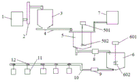
FIG. 1 is a schematic structural diagram of an automated slurry tank for manganese-zinc ferrite material of the present invention;
the parts in the drawings are numbered as follows: 1. the vibrating mill, 2, the lifting machine, 3, the feed bin, 4, screw feeder, 5, change the thick liquid pond, 501, first motor electricity is even, 502, first stirring rod, 6, measurement stirring pond, 601, second motor electricity is even, 602, second stirring rod, 7, the water storage tank, 8, change thick liquid ejection of compact pump, 9, measurement discharge pump, 10, pipeline, 11, sander, 12, the pneumatic valve of sanding.
Detailed Description
The following detailed description of the preferred embodiments of the present invention will be provided in conjunction with the accompanying drawings, so as to enable those skilled in the art to more easily understand the advantages and features of the present invention, and thereby define the scope of the invention more clearly and clearly.
Referring to fig. 1, an embodiment of the present invention includes:
the utility model provides a manganese zinc ferrite material is with automatic thick liquid pond, the front end links to each other with the mill that shakes 1, and the tail end links to each other with a plurality of sand mills 11 for carry each sand mill 11 after the material slurrying that will shake the mill, include: a feeding mechanism, a slurry melting system, a slurry conveying system and an electronic control system (not shown).
The feeding mechanism comprises a lifting machine 2 connected with the vibrating mill 1, a bin 3 connected with the lifting machine 2, and a spiral feeder 4 connected with the bin 3. The lifter 2 is a bucket type lifter, is internally provided with a material receiving box and a conveying belt and is used for automatically lifting the materials which are vibrated and ground in the vibrating grinder 1 and feeding the materials into the material bin 3.
The slurry melting system comprises a slurry melting tank 5, a metering stirring tank 6 and a water storage tank 7, and the slurry conveying system comprises a slurry melting discharge pump 8, a metering discharge pump 9 and a conveying pipeline 10. The slurry melting tank 5 is connected with the spiral feeder 4, and the spiral feeder 4 is used for feeding the materials in the stock bin 3 into the slurry melting tank 5; the water storage tank 7 is connected with the slurry melting tank 5, and water in the water storage tank 7 is properly pumped into the slurry melting tank 5 through an electronic control system and mixed with the slurry in the slurry melting tank 5 to melt the slurry; a first motor 501 and a first stirring rod 502 electrically connected with the first motor 501 are arranged in the slurry pond 5, the first motor 501 drives the first stirring rod 502 to rotate and stir, and materials and water in the slurry pond 5 are mixed, stirred and homogenized; the slurry melting tank 5 is connected with the metering stirring tank 6 through a slurry melting discharge pump 8, and slurry melting in the slurry melting tank 5 is pumped into the metering stirring tank 6 through a closed pipeline through the slurry melting discharge pump 8; a second motor 601 and a second stirring rod 602 electrically connected with the second motor 601 are arranged in the metering stirring tank 6, and the second motor 601 drives the second stirring rod 602 to rotate and stir so as to uniformly stir the slurry in the metering stirring tank 6; the metering stirring pool 6 is connected with the conveying pipeline 10 through a metering discharge pump 9, and slurry in the metering stirring pool 6 is conveyed into the conveying pipeline 10 through the metering discharge pump 9; the conveying pipeline 10 is connected with a plurality of sand mills 11 and is sequentially conveyed into the sand mills 11 through the conveying pipeline 10.
Each of the sanders 11 is equipped with a sanding pneumatic valve.
The electronic control system is respectively connected with the slurry melting system and the slurry conveying system, so that the slurry melting tank 5 and the metering stirring tank 6 can automatically detect the weight of the materials and the water, if the weight of the materials and the water exceeds a metering standard, an alarm is automatically given, and after the alarm is eliminated, automatic measurement is continued; meanwhile, the slurry in the metering and stirring tank 6 can be automatically fed for multiple times, and can be conveyed in equal amount to different sand mills 11.
The utility model discloses in, 11 total five of sand mill, the ground paste in the measurement stirring pond 6 passes through electronic control system (2400 KG at every turn, water adds 1100KG, every sand 580 KG), squeezes into in each sand mill 11 in proper order.
The working process is as follows: the pre-sintered material and the vibration grinding material are automatically conveyed to a stock bin 3 through a bucket elevator 2, and then the material in the stock bin 3 is automatically conveyed to a slurry pond 5 through a spiral feeder; stirring and pulping the materials in the pulping tank 5, and pumping the materials into the metering stirring tank 6 through a closed pipeline by a pulping discharge pump 8; the slurry in the metering and stirring pool 6 is automatically fed in an equivalent amount for a plurality of times under the control of an electronic control system, and is sequentially pumped into each sand mill 11 through a metering discharge pump 9 and a conveying pipeline 10.
The utility model discloses a manganese zinc ferrite material is with automatic thick liquid pond, through the structural design who adopts electronic control system and mechanical system to combine together, the operation flow has been simplified, the dust pollution problem in the sanding process and the turnover and the transportation problem of sanding materials have been solved, the degree of automation of production has been improved, workman's intensity of labour has been reduced, operational environment and operating condition have been improved greatly simultaneously, it flies upward to reduce the dust, improve staff's work efficiency and enthusiasm, production efficiency has been improved.
In the description of the present invention, it should be noted that the terms "upper", "lower", "left", "right", "inner", "outer", etc. indicate the position or positional relationship based on the position or positional relationship shown in the drawings, or the position or positional relationship that the products of the present invention are usually placed when used, and are only for convenience of description and simplification of the description, but do not indicate or imply that the device or element to which the term refers must have a specific orientation, be constructed and operated in a specific orientation, and thus, should not be construed as limiting the present invention. The above description is only a preferred embodiment of the present invention and is not intended to limit the present invention, and various modifications and changes may be made by those skilled in the art. Any modification, equivalent replacement, or improvement made within the spirit and principle of the present invention should be included in the protection scope of the present invention.
The above only is the embodiment of the present invention, not limiting the patent scope of the present invention, all the equivalent structures or equivalent processes that are used in the specification and the attached drawings or directly or indirectly applied to other related technical fields are included in the patent protection scope of the present invention.