CN210950215U - Water pipe support frame for crossing road - Google Patents
Water pipe support frame for crossing road Download PDFInfo
- Publication number
- CN210950215U CN210950215U CN201920915094.3U CN201920915094U CN210950215U CN 210950215 U CN210950215 U CN 210950215U CN 201920915094 U CN201920915094 U CN 201920915094U CN 210950215 U CN210950215 U CN 210950215U
- Authority
- CN
- China
- Prior art keywords
- water pipe
- support frame
- vertical rod
- landing leg
- road
- Prior art date
- Legal status (The legal status is an assumption and is not a legal conclusion. Google has not performed a legal analysis and makes no representation as to the accuracy of the status listed.)
- Active
Links
Images

Abstract
The support frame for the water pipe crossing the road comprises a transverse pipe, two groups of supporting legs and a bracket, wherein the bracket is arranged on the outer side of each supporting leg in an upward inclining mode, the two groups of supporting legs are respectively arranged at the bottoms of the two ends of the transverse pipe, the bracket comprises a support and a guide groove, the bottom of the support is arranged on the supporting legs, and the guide groove is arranged at the top of the support. The utility model has simple structure, convenient assembly and disassembly and repeated use; the construction efficiency of the water pipe crossing the road is improved, the process cost input is reduced, and the use safety is guaranteed. Moreover, the supporting frame can be adjusted according to the width and the erection height of the road, the requirements of erecting water pipes under various conditions are met, and the practicability is high.
Description
Technical Field
The utility model belongs to the building construction field, especially a water pipe support frame of crossing over road.
Background
In engineering construction, the water pipe can pass through the road according to construction requirements, and the passing method generally comprises underground passing of the road and road surface passing of the road.
Underground road crossing methods including open cut method and pipe jacking method; the open cut method is generally completed by the procedures of trench excavation, trench building protection or steel sleeve installation, water pipe laying, trench backfilling and the like before a road surface is formed; the pipe jacking method is that after a road surface is formed, two sides of the road surface are respectively dug with a well, and the well is started to pass through the road to reach another well pit to realize the passing; the two methods for underground road crossing have the disadvantages of high investment cost, more working procedures and complex construction for small-diameter water pipes.
The road pavement crossing method mainly adopts the arrangement of the blocking ridge, generally, after the road pavement is formed, the water pipe is directly paved on the road pavement, the two sides of the water pipe adopt concrete or special rubber belts and other media to form the blocking ridge, the water pipe is protected, the water pipe is prevented from being damaged by passing vehicles, the road ridge and the water pipe are easily damaged by long-term use, and certain influence can be caused on the passing vehicles. Therefore, how to manufacture the water pipe supporting frame capable of solving the problems in the prior art and crossing roads becomes a technical problem to be solved.
SUMMERY OF THE UTILITY MODEL
The utility model discloses just based on above-mentioned technical problem, provided a water pipe support frame of strideing across road, compared with prior art, used the utility model discloses it is less to erect the water pipe cost and drop into, and the pipeline ann tears the convenience open, and construction speed is fast, and the water pipe is difficult damaged.
In view of this, the utility model provides a water pipe support frame of crossing road, it includes: violently pipe, landing leg and bracket, landing leg outside tilt up be provided with the bracket, the landing leg be two sets of, two sets of the landing leg set up respectively violently manage both ends bottom, the bracket include support and guide slot, support bottom set up the landing leg on, the support top be provided with the guide slot.
In the technical scheme, the support frame is used for being erected on a road, the water pipe penetrates through the road surface through the transverse pipe, and the vehicle penetrates through the bottom of the support frame. The water pipes on the two sides of the transverse pipe are obliquely erected through the bracket, so that the water pipes can be prevented from being bent; the bottoms of the supporting legs are fixed by being buried underground, so that the supporting frame is convenient to mount and dismount, the erection site can be adjusted according to the construction condition, and the supporting frame can be repeatedly recycled; the integral structure is simple, the construction speed is accelerated, the process cost input is reduced, and the use safety is guaranteed.
In this technical scheme, preferred, violently the pipe be scalable violently the pipe, scalable violently the pipe include many diameters increase progressively in proper order and overlap and establish the body together, face two mutually the body between be provided with spacing fastener respectively.
In the technical scheme, the telescopic transverse pipe is preferably simple in structure, the length of the transverse pipe can be adjusted according to different road surface widths, and the erection requirements of the support frame on the road surfaces with different widths are met; when the support frame is idle or transported, the telescopic transverse pipe can be contracted to reduce the volume of the support frame.
In this technical scheme, it is preferred, the landing leg include pole setting and bracing, the pole setting set up violently manage the bottom, the bracing be two, two the top of bracing respectively through the articulated elements setting be in the left and right sides of pole setting.
In above-mentioned technical scheme, preferred, the landing leg includes pole setting and bracing, can fix the support frame through the bracing according to different road conditions, has strengthened the overall stability of support frame. When the support frame is idle or transported, the inclined strut is folded towards the direction of the support leg through the hinge piece, and the size of the support frame can be reduced.
In this technical scheme, preferably, the pole setting include the pole setting cover with the activity set up the pole setting of extension in the pole setting cover cavity structure, the pole setting sheathe in be provided with the bolt hole, the pole setting cover with the pole setting of extension pass through the setting in the bolt hole bolt fastening.
In the above technical solution, preferably, the vertical rod includes a vertical rod sleeve and a lengthened vertical rod arranged in a cavity structure of the vertical rod sleeve, so that the vertical rod has a telescopic function, and the height of the support frame can be adjusted through the vertical rod according to different erection requirements; the telescopic structure is simple, convenient to adjust and use and convenient to transport.
In this embodiment, preferably, the bottom of the elongated vertical rod is provided with a pointed insertion portion.
In the above technical scheme, preferably, the tip insertion part is provided, so that the support frame can be conveniently inserted into soil when in use; when the support frame is idle, the tip insertion part is contracted in the upright sleeve, so that potential safety hazards caused by the idle state of the tip insertion part are avoided.
In this technical solution, preferably, the outer surface of the cross bar is provided with a striking coating.
In above-mentioned technical scheme, preferably, the surface of horizontal pole is provided with striking coating, can remind passing vehicle, also has limit for height effect.
In this technical scheme, preferably, the material of violently pipe, landing leg and the support be seamless steel pipe, the material of guide slot be half round steel pipe.
In above-mentioned technical scheme, preferred, seamless steel pipe and semicircle steel pipe are the job site material, and the prefabrication installation of being convenient for is used, and moreover, it has higher strength, has increased the whole life of support frame.
The utility model provides a water pipe supporting frame for crossing roads, compared with the prior art, the utility model has simple structure, convenient assembly and disassembly and repeated use; the construction efficiency of the water pipe crossing the road is improved, the process cost input is reduced, and the use safety is guaranteed. Moreover, the supporting frame can be adjusted according to the width and the erection height of the road, the requirements of erecting water pipes under various conditions are met, and the practicability is high.
Drawings
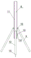
Fig. 1 shows a schematic view of the cross tube structure of the present invention;
fig. 2 shows a schematic structural view of the support leg of the present invention;
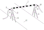
fig. 3 shows a schematic view of the usage state of the present invention;
in the figure, a transverse pipe 1, supporting legs 2, a bracket 3, a bracket 4, a guide groove 5, a pipe body 6, a limiting clamping piece 7, an upright post 8, an inclined strut 9, a hinge piece 10, an upright post sleeve 11, an elongated upright post 12, a bolt hole 13, a bolt 14, an insertion part 15, a water pipe 16 and a road 17 are arranged.
Detailed Description
In order to make the aforementioned objects, features and advantages of the present invention more clearly understood, the present invention will be described in further detail with reference to the accompanying drawings and detailed description.
In the following description, numerous specific details are set forth in order to provide a thorough understanding of the present invention, however, the present invention may be practiced in other ways than those specifically described herein, and thus the scope of the present invention is not limited by the disclosure below.
The technical solution of the present invention is further explained below with reference to fig. 1, fig. 2 and fig. 3.
A first embodiment, as shown in fig. 1, 2 and 3, is a water pipe support frame for crossing a road, comprising: violently manage 1, landing leg 2 and bracket 3, 2 outsides of landing leg upwards 45 slope welding set up be provided with bracket 3, landing leg 2 be two sets of, two sets of landing leg 2 weld respectively and set up violently manage 1 both ends bottom, bracket 3 include support 4 and guide slot 5, support 4 bottom welding set up landing leg 2 on, support 4 top welding be provided with 16 footpaths of delivery pipe match the guide slot 5.
Violently pipe 1 be scalable violently pipe 1, scalable violently pipe 1 include many diameters increase progressively in proper order and overlap and establish body 6 together, face two mutually body 6 between be provided with spacing fastener 7 respectively. Landing leg 2 include pole setting 8 and bracing 9, pole setting 8 set up violently pipe 1 bottom, bracing 9 be two, two bracing 9's top pass through articulated elements 10 respectively and set up the left and right sides of pole setting 8.
The upright rod 8 comprises an upright rod sleeve 11 and a lengthened upright rod 12 movably arranged in a cavity structure of the upright rod sleeve 11, a bolt hole 13 is formed in the upright rod sleeve 11, and the upright rod sleeve 11 and the lengthened upright rod 12 are fixed through a bolt 14 arranged in the bolt hole 13. The bottom of the lengthened vertical rod 12 is provided with a pointed insertion part 15. The outer surface of the cross rod is provided with a striking coating. The transverse pipe 1, the supporting legs 2 and the support 4 are all made of seamless steel pipes, and the guide groove 5 is made of semicircular steel pipes. The upright rod 8 is a phi 108 seamless steel pipe, and the bottom end of the upright rod is buried underground by 0.8 to 1.0 m; the inclined strut 9 is a phi 48 steel pipe, the inclined angle between the inclined strut 9 and the upright stanchion 8 is 30-45 degrees, and the bottom end of the inclined strut is buried underground for 0.5-0.8 m; the support 4 is a phi 32 steel pipe.
When the device is installed, the horizontal pipe 1 and the supporting legs 2 are respectively adjusted according to the width and erection height requirements of the road 17; the adjusted support frame can be installed by the aid of a small truck crane, the vertical rod 8 is buried by manual digging, and the support frame is manually tamped layer by layer during backfilling; when the water pipe 16 is erected, the water pipe 16 is passed through the road through the horizontal pipe 1, and both ends of the water pipe 16 passed through the horizontal pipe 1 are supported by the brackets 3.
The above description is only for the purpose of illustrating the preferred embodiments of the present invention and is not to be construed as limiting the present invention, but is susceptible to various modifications and changes by those skilled in the art. Any modification, equivalent replacement, or improvement made within the spirit and principle of the present invention should be included in the protection scope of the present invention.
Claims (7)
1. The utility model provides a water pipe support frame of crossing road which characterized in that: including violently managing, landing leg and bracket, landing leg outside tilt up be provided with the bracket, the landing leg be two sets of, two sets of the landing leg set up respectively violently manage both ends bottom, the bracket include support and guide slot, support bottom set up the landing leg on, the support top be provided with the guide slot.
2. The water pipe support frame for crossing roads of claim 1, wherein: the transverse pipe is a telescopic transverse pipe, the telescopic transverse pipe comprises a plurality of pipes, the diameters of the pipes are sequentially increased in an increasing mode and the pipes are sleeved together, and two adjacent pipes are provided with limiting clamping pieces respectively.
3. The water pipe support frame for crossing roads of claim 2, wherein: the landing leg include pole setting and bracing, the pole setting set up violently manage the bottom, the bracing be two, two the top of bracing be in through the articulated elements setting respectively the left and right sides of pole setting.
4. The water pipe support frame for crossing roads of claim 3, wherein: the vertical rod comprises a vertical rod sleeve and a lengthened vertical rod movably arranged in the cavity structure of the vertical rod sleeve, a bolt hole is formed in the vertical rod sleeve, and the vertical rod sleeve and the lengthened vertical rod are fixed through a bolt arranged in the bolt hole.
5. The water pipe support frame for crossing roads of claim 4, wherein: the bottom of the lengthened vertical rod is provided with a pointed insertion part.
6. The water pipe support frame for crossing roads of claim 5, wherein: the outer surface of the transverse pipe is provided with a striking coating.
7. The water pipe support frame for crossing roads of claim 6, wherein: the transverse pipe, the supporting legs and the support are all made of seamless steel pipes, and the guide groove is made of semicircular steel pipes.
Priority Applications (1)
| Application Number | Priority Date | Filing Date | Title |
|---|---|---|---|
| CN201920915094.3U CN210950215U (en) | 2019-06-18 | 2019-06-18 | Water pipe support frame for crossing road |
Applications Claiming Priority (1)
| Application Number | Priority Date | Filing Date | Title |
|---|---|---|---|
| CN201920915094.3U CN210950215U (en) | 2019-06-18 | 2019-06-18 | Water pipe support frame for crossing road |
Publications (1)
| Publication Number | Publication Date |
|---|---|
| CN210950215U true CN210950215U (en) | 2020-07-07 |
Family
ID=71377446
Family Applications (1)
| Application Number | Title | Priority Date | Filing Date |
|---|---|---|---|
| CN201920915094.3U Active CN210950215U (en) | 2019-06-18 | 2019-06-18 | Water pipe support frame for crossing road |
Country Status (1)
| Country | Link |
|---|---|
| CN (1) | CN210950215U (en) |
Cited By (1)
| Publication number | Priority date | Publication date | Assignee | Title |
|---|---|---|---|---|
| CN111946901A (en) * | 2020-08-22 | 2020-11-17 | 常德市俊德科技发展有限公司 | Road bending pipeline arch support protector that municipal heating used |
-
2019
- 2019-06-18 CN CN201920915094.3U patent/CN210950215U/en active Active
Cited By (2)
| Publication number | Priority date | Publication date | Assignee | Title |
|---|---|---|---|---|
| CN111946901A (en) * | 2020-08-22 | 2020-11-17 | 常德市俊德科技发展有限公司 | Road bending pipeline arch support protector that municipal heating used |
| CN111946901B (en) * | 2020-08-22 | 2021-11-23 | 安徽华景建设有限公司 | Road bending pipeline arch support protector that municipal heating used |
Similar Documents
| Publication | Publication Date | Title |
|---|---|---|
| CN207348483U (en) | The working portable rain-proof shelter of underground pipe gallery | |
| CA2849099A1 (en) | Foundation apparatus and method | |
| CN111851979A (en) | Movable operating system for road slope anchor bolt support | |
| CN214362621U (en) | Structure is widened to active service highway pile type stock foam light soil | |
| CN206941431U (en) | Across the anti-electric frame of the protection of railway line | |
| CN210950215U (en) | Water pipe support frame for crossing road | |
| KR101375525B1 (en) | A sidewalk enlargement installation | |
| CN211498507U (en) | Whole reassembling type protection rack | |
| CN218150940U (en) | Adjustable tunnel is first to be propped up and two lining supporting devices | |
| CN114775692B (en) | Reinforcing structure and reinforcing method for pavement around inspection well | |
| CN113622237B (en) | Transverse roadbed reinforcing device | |
| CN202482767U (en) | Steel tube bailey beam column type support | |
| CN210262617U (en) | Protector is used in town road construction | |
| CN214245300U (en) | Pipeline suspension structure spanning long and narrow foundation pit | |
| CN212406058U (en) | Movable operating system for road slope anchor bolt support | |
| CN110258528B (en) | Assembled and inserted self-clamping type prefabricated hollow underground continuous wall and construction method thereof | |
| JP5032255B2 (en) | Rockfall protection and avalanche prevention facility | |
| CN205657401U (en) | Cable bridge | |
| CN206267871U (en) | A kind of porous pre-buried channel flow | |
| CN214662557U (en) | Light high-pressure flexible gas pipe road crossing pipe frame | |
| CN205205676U (en) | Portable beiLei beam operation platform of cast -in -situ box girder | |
| CN103806443B (en) | A kind of pile tube for ground minor installation and manufacture method thereof | |
| CN203701082U (en) | Tube pile for small ground facilities | |
| CN216006776U (en) | Temporary vehicle channel laying and erecting device for municipal construction | |
| CN219137365U (en) | Groove temporary bridge |
Legal Events
| Date | Code | Title | Description |
|---|---|---|---|
| GR01 | Patent grant | ||
| GR01 | Patent grant |