CN210906437U - Kitchen waste crusher - Google Patents
Kitchen waste crusher Download PDFInfo
- Publication number
- CN210906437U CN210906437U CN201921032799.7U CN201921032799U CN210906437U CN 210906437 U CN210906437 U CN 210906437U CN 201921032799 U CN201921032799 U CN 201921032799U CN 210906437 U CN210906437 U CN 210906437U
- Authority
- CN
- China
- Prior art keywords
- outer cylinder
- crushing shaft
- crushing
- guide plate
- kitchen waste
- Prior art date
- Legal status (The legal status is an assumption and is not a legal conclusion. Google has not performed a legal analysis and makes no representation as to the accuracy of the status listed.)
- Active
Links
Images


Landscapes
- Crushing And Pulverization Processes (AREA)
Abstract
The utility model provides a kitchen waste crusher, kitchen waste crusher includes rotatable outer barrel, the both ends of outer barrel are feed end and discharge end respectively, be equipped with a plurality of stock guides on the inner wall of outer barrel; and the crushing shaft is arranged inside the outer barrel body, the crushing shaft is provided with a crushing blade, the crushing shaft and the outer barrel body are eccentrically arranged, and the direction of the crushing shaft and the direction of the outer barrel body are the same. The utility model provides an outer barrel of kitchen garbage breaker and broken axle eccentric settings can reduce broken axle diameter, reduces the processing degree of difficulty of broken axle, has increased inside punishment in advance space simultaneously, increases equipment throughput, adopts eccentric settings can also effectively guarantee the contact of broken axle and material, realizes the effective breakage to the material; the outer cylinder body and the crushing shaft have the same rotation direction, so that the stress of the crushing shaft can be reduced, the energy consumption is reduced, the production efficiency is improved, and the cost is reduced.
Description
Technical Field
The utility model relates to a waste treatment technical field, specifically, the utility model relates to a kitchen garbage breaker.
Background
The kitchen waste is food waste generated in daily business and living processes of catering units and families, and is one of main components of urban organic waste. The kitchen waste takes organic substances such as starch, dietary fibers, protein, lipids and the like as main components, also contains inorganic salts, and has the characteristics of high grease, high salt content, high moisture content, high organic matter content, easiness in stinking, acidification, biodegradation and the like.
At present, anaerobic digestion has gradually become an important development direction of kitchen waste treatment technology, and the anaerobic digestion generates methane which can be used as energy. Because a large amount of sundries such as plastic bags and the like exist in the kitchen waste and are easy to wind, the kitchen waste needs to be crushed before anaerobic digestion reaction; meanwhile, the kitchen waste is high in viscosity, organic matters and impurities are adhered to each other, and if the kitchen waste is not broken and scattered, the extraction of the organic matters and the sorting of the impurities in the kitchen waste are not facilitated. Meanwhile, the subsequent anaerobic digestion reaction is facilitated after the crushing.
However, the existing kitchen waste crusher has the problems of large and heavy volume, high processing and manufacturing cost and high operating cost, the crushing effect is not ideal, the situation of material blockage and material leakage is easy to occur, the crusher is maintained frequently, and the production and operation efficiency is reduced.
Therefore, a new kitchen waste crusher needs to be provided to solve the above problems.
SUMMERY OF THE UTILITY MODEL
In the summary section a series of concepts in a simplified form is introduced, which will be described in further detail in the detailed description section. The inventive content does not imply any attempt to define the essential features and essential features of the claimed solution, nor is it implied to be intended to define the scope of the claimed solution.
Aiming at the defects of the prior art, the utility model provides a kitchen waste crusher, which comprises a rotatable outer cylinder body, wherein the two ends of the outer cylinder body are respectively a feeding end and a discharging end, and the inner wall of the outer cylinder body is provided with a plurality of guide plates; and the crushing shaft is arranged inside the outer barrel body, the crushing shaft is provided with a crushing blade, the crushing shaft and the outer barrel body are eccentrically arranged, and the direction of the crushing shaft and the direction of the outer barrel body are the same.
In one embodiment, the guide plates respectively comprise a feeding section guide plate, a crushing section guide plate and a discharging section guide plate from the feeding end to the discharging end, wherein the crushing section guide plate is provided with a bending angle for lifting the material, and the feeding section guide plate and the crushing section guide plate are obliquely arranged.
In one embodiment, the discharging section material guide plate is in a spiral blade shape.
In one embodiment, the bending angle of the material guide plate of the crushing section is 140-160 degrees.
In one embodiment, the included angle between the feeding section material guide plate and the axial direction of the outer cylinder body is 50-70 degrees, and the included angle between the crushing section material guide plate and the axial direction of the outer cylinder body is 5-15 degrees.
In one embodiment, the eccentric distance of the outer cylinder from the crushing shaft is 130mm-150 mm.
In one embodiment, the kitchen waste crusher further comprises a crushing shaft power device arranged at the end part of the crushing shaft and an outer barrel power device arranged at the bottom of the outer barrel.
In one embodiment, the kitchen waste crusher further comprises two front supporting wheels and two rear supporting wheels which are arranged at the bottom of the outer cylinder body and used for fixing the outer cylinder body.
In one embodiment, the kitchen waste crusher further comprises a feeding port arranged at the feeding end and a pushing spiral positioned below the feeding port, and the pushing spiral is used for pushing the material from the feeding port to the inside of the outer barrel.
In one embodiment, the discharge end is provided with a discharge cover.
The utility model provides an outer barrel of kitchen garbage breaker and broken axle eccentric settings can reduce broken axle diameter, reduces the processing degree of difficulty of broken axle, has increased inside punishment in advance space simultaneously, increases equipment throughput, adopts eccentric settings can also effectively guarantee the contact of broken axle and material, realizes the effective breakage to the material; the outer cylinder body and the crushing shaft have the same rotation direction, so that the stress of the crushing shaft can be reduced, the energy consumption is reduced, the production efficiency is improved, and the cost is reduced.
Drawings
The following drawings of the present invention are used herein as part of the present invention for understanding the present invention. There are shown in the drawings, embodiments and descriptions of the invention, which are used to explain the principles and devices of the invention. In the drawings, there is shown in the drawings,
fig. 1 is a schematic structural view of a kitchen waste crusher according to an embodiment of the present invention;
FIG. 2 is a schematic view of an outer cylinder fixing riding wheel of the kitchen waste crusher shown in FIG. 1;
fig. 3 is a schematic view illustrating an installation of a guide plate of an outer cylinder of the kitchen waste crusher shown in fig. 1;
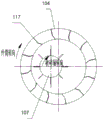
FIG. 4 is a cross-sectional view of the kitchen waste crusher shown in FIG. 1 with the outer cylinder and the crushing shaft eccentrically installed;
fig. 5 is a sectional view of a breaking section material guide plate of the kitchen waste breaker shown in fig. 1.
Reference numerals:
101: crushing shaft power plant 102: feed inlet
103: pushing screw 104: outer cylinder
105: the large ring gear 106: front rolling ring
107: the crushing shaft 108: rear rolling ring
109: rear fixed bearing 110: discharging cover
111: base 112: rear riding wheel
113: front idler 114: outer cylinder power device
115: front fixed bearing 116: material guide plate for feeding section
117: the crushing section guide plate 118: discharging section material guide plate
119: water baffle
Detailed Description
In the following description, numerous specific details are set forth in order to provide a more thorough understanding of the present invention. It will be apparent, however, to one skilled in the art, that the present invention may be practiced without one or more of these specific details. In other instances, well-known features have not been described in order to avoid obscuring the present invention.
In order to thoroughly understand the present invention, detailed steps will be provided in the following description in order to explain the kitchen waste crusher provided by the present invention. It is apparent that the practice of the invention is not limited to the specific details known to those skilled in the art. The preferred embodiments of the present invention are described in detail below, however, other embodiments of the present invention are possible in addition to these detailed descriptions.
It will be understood that the terms "comprises" and/or "comprising," when used in this specification, specify the presence of stated features, integers, steps, operations, elements, and/or components, but do not preclude the presence or addition of one or more other features, integers, steps, operations, elements, components, and/or groups thereof.
At present, a part of domestic kitchen waste crusher mainly comprises an outer barrel and a crushing shaft, wherein the crushing shaft and the outer barrel are concentrically arranged and run opposite to the outer barrel; install broken blade on the broken axle, install the stock guide on the barrel, the stock guide plays the effect of raising the material and promoting the material and advance, and the material is raised to broken epaxial, is broken by pivoted blade. However, the above structure has the following drawbacks:
1. the material lifting function of the material guide plate is poor, and the material cannot be effectively lifted, so that the material cannot be effectively crushed;
2. the crushing shaft and the outer barrel are arranged concentrically, the diameter of the crushing shaft needs to be increased, the gap between the crushing shaft and the guide plate of the outer barrel is ensured to be within 50mm, the crushing shaft can be in contact with the material when rotating, the material is crushed, and the processing and manufacturing difficulty and the cost of equipment are increased due to the increase of the diameter of the crushing shaft;
3. broken axle and urceolus are operation in opposite directions, and broken axle atress is too big in the operation, and the energy consumption is too big, has too broken condition in the crushing process, and the broken particle diameter undersize of kitchen garbage is unfavorable for the screening of debris, has the easy condition that blocks up of discharge end material simultaneously.
In order to solve the problems, the embodiment of the utility model provides a kitchen waste crusher, which reduces the diameter of a crushing shaft and reduces the processing difficulty of the crushing shaft; the structure of the material guide plate is optimized, so that materials can be lifted to the crushing shaft, and the materials can be effectively crushed; the end part is discharged in a spiral blade rapid discharging mode, so that material blockage is avoided; the steering of the outer cylinder body is the same as that of the crushing shaft, so that the stress of the crushing shaft is reduced, the energy consumption is reduced, the production efficiency is improved, and the cost is reduced.
In order to thoroughly understand the present invention, a detailed structure will be provided in the following description in order to explain the technical solution provided by the present invention. The preferred embodiments of the present invention are described in detail below, however, other embodiments of the present invention are possible in addition to these detailed descriptions.
The kitchen waste crusher of the present invention will be further described with reference to the accompanying drawings.
As shown in fig. 1, the utility model discloses a kitchen garbage breaker of embodiment includes: the device comprises a rotatable outer cylinder 104, wherein a feeding end and a discharging end are respectively arranged at two ends of the outer cylinder 104, and a plurality of material guide plates are arranged on the inner wall of the outer cylinder 104; and a crushing shaft 107 provided inside the outer cylinder 104, wherein a plurality of groups of crushing blades are provided on the crushing shaft 107, the crushing shaft 107 is eccentrically provided to the outer cylinder 104 (see fig. 4), and the crushing shaft 107 and the outer cylinder 104 are rotated in the same direction.
As shown in fig. 4, by eccentrically arranging the outer cylinder 104 and the crushing shaft 107, the minimum distance between the outer cylinder 104 and the crushing shaft 107 can be reduced, and the diameter of the crushing shaft 107 can be reduced, which is also beneficial to increasing the inner space of the outer cylinder 104, increasing the processing capacity of the equipment, and avoiding blockage. In this embodiment, the eccentric distance is set to 130-150mm, and the diameter of the crushing shaft 107 can be reduced to 400-500 mm, so that the material lifted by the material guide plate can fall onto the crushing shaft 107, and the material can be effectively crushed.
By enabling the outer cylinder 104 and the crushing shaft 107 to rotate in the same direction, the stress of the crushing shaft 107 can be reduced, the same crushing effect can be achieved, the energy consumption can be reduced, the production cost can be reduced, and the situation of over crushing cannot occur in the crushing process.
Specifically, referring to fig. 1, the left side of the outer cylinder 104 is a feeding end, and the right side is a discharging end. The feeding end is provided with a feeding hole 102 and a pushing screw 103 positioned below the feeding hole 102. The material from the feed inlet 102 enters the inner part of the outer cylinder 104 under the pushing of the pushing screw 103. The pusher screw 103 is provided coaxially with the crushing shaft 107, and is rotated together with the crushing shaft by the driving of the crushing shaft power unit 101 provided at one end of the crushing shaft 107. The front fixed bearing 115 and the rear fixed bearing 109 are used for fixing at both ends of the shaft.
The material entering the interior of the outer cylinder 104 is moved backwards by the guide plate. In the embodiment of the utility model, the stock guide is divided into three sections. As shown in fig. 3, the guide plates sequentially include a feeding section guide plate 116, a crushing section guide plate 117 and a discharging section guide plate 118 from the feeding end to the discharging end.
The feeding section material guide plate 116 is obliquely arranged, the included angle between the feeding section material guide plate and the axial direction of the outer cylinder 104 is 50-70 degrees, and a larger inclination angle can ensure that materials can not stay at the end part of the outer cylinder any more, so that the materials are prevented from overflowing. For example, the angle between the feeding-section material guiding plate 116 and the axial direction of the outer cylinder may be 60 °. The feeding-section guide plates 116 are uniformly arranged along the circumference of the outer cylinder, and the number thereof is, for example, 6.
As shown in fig. 5, the material guiding plate 117 of the crushing section has a bending angle for lifting the material, so that the lifted material can fall onto the crushing shaft, and the crushing effect is ensured. In order to ensure the material lifting effect, the bending angle is set between 140 degrees and 160 degrees, and is preferably 150 degrees.
The crushing section guide plate 117 is also inclined, and the inclination angle thereof is smaller than that of the feeding section guide plate 116, which is mainly used for ensuring a certain retention time in the material outer cylinder 104. The angle of inclination is in the range of 5 to 15, for example 10. The crushing section guide plates 117 are uniformly arranged along the circumference of the outer cylinder, and the number thereof is, for example, 12.
The discharging section material guide plate 118 is in a spiral blade shape, and the material guide speed of the material guide plate in the shape is high, so that material blockage can be avoided. The discharging section guide plates 118 are uniformly arranged along the circumference of the outer cylinder, and the number of the discharging section guide plates is 6, for example.
As shown in fig. 1, the discharge end of the outer cylinder 104 is provided with a discharge cover 110. The discharge cover 110 can prevent the material output by the crusher from splashing outwards. The discharging cover 110 is opened downward for dropping the crushed material downward. In one embodiment, the outer cylinder 104 is further provided with a water baffle 119 at the end.
As shown in fig. 2, an outer cylinder power unit 114 for driving the outer cylinder 104 to rotate is provided at the bottom of the outer cylinder 104. Specifically, the bottom of the outer cylinder 104 is provided with a front riding wheel 113 and a rear riding wheel 112 for fixing the outer cylinder, and the front riding wheel 113 and the rear riding wheel 112 respectively comprise two riding wheels symmetrically arranged on two sides of the outer cylinder 104. The two front supporting wheels or the two rear supporting wheels and the axle center of the outer cylinder body form an equilateral triangle, so that the outer cylinder body can be stably supported to rotate.
The outer cylinder power plant 114 is illustratively disposed between and in powered communication with the two front idlers 113. The outer cylinder 104 is provided with a front rolling ring 106 engaged with the gear on the front riding wheel 113 and a rear rolling ring 108 engaged with the gear on the rear riding wheel 112, and the riding wheel mechanism drives the outer cylinder 104 to rotate through gear transmission. The outer barrel 104 is also provided with a bull gear 105 which meshes with the pinion of the outer barrel power plant 114.
The utility model discloses kitchen garbage breaker's work flow as follows: the material falls into feed inlet 102, is pushed inside outer barrel 104 by pushing away material spiral 103, is flowed to the broken section by the quick water conservancy diversion of feed section stock guide 116, and at the rotatory in-process of outer barrel 104, broken section stock guide 117 lifts the material to with outer barrel 104 syntropy rotatory crushing axle 107 on, is smashed at random by the rotatory crushing blade of high speed, the material after the breakage is finally under the effect of play material section stock guide 118 directly the ejection of compact through ejection of compact cover 110, carries to next handling procedure.
The utility model discloses kitchen garbage breaker has following advantage:
1. the crushing shaft and the outer barrel are arranged eccentrically, so that the diameter of the crushing shaft is effectively reduced, the processing and manufacturing difficulty of the crushing shaft is reduced, the production cost is reduced, the internal material passing space is increased, and the processing capacity of equipment is increased; the eccentric arrangement can also effectively ensure the contact between the crushing shaft and the material, and realize the effective crushing of the material;
2. the guide plates in the outer barrel body are arranged in three sections and are divided into different working areas, meanwhile, the guide plates in the crushing sections are designed into folding angle types, so that materials can be effectively lifted, and effective crushing of the materials is guaranteed;
3. adopt the direct ejection of compact mode of ejection of compact cover, reduce material transfer process, improve work efficiency.
Unless defined otherwise, technical and scientific terms used herein have the same meaning as commonly understood by one of ordinary skill in the art to which this invention belongs. The terminology used herein is for the purpose of describing particular embodiments only and is not intended to be limiting of the invention. Terms such as "disposed" and the like, as used herein, may refer to one element being directly attached to another element or one element being attached to another element through intervening elements. Features described herein in one embodiment may be applied to another embodiment, either alone or in combination with other features, unless the feature is otherwise inapplicable or otherwise stated in the other embodiment.
The present invention has been described in terms of the above embodiments, but it is to be understood that the above embodiments are for purposes of illustration and description only and are not intended to limit the invention to the described embodiments. Furthermore, it will be understood by those skilled in the art that the present invention is not limited to the embodiments described above, and that many more modifications and variations are possible in light of the teaching of the present invention and are within the scope of the invention as claimed. The scope of the invention is defined by the appended claims and equivalents thereof.
Claims (10)
1. The utility model provides a kitchen garbage breaker, its characterized in that, kitchen garbage breaker includes:
the device comprises a rotatable outer cylinder body, a plurality of guide plates and a plurality of guide plates, wherein a feeding end and a discharging end are respectively arranged at two ends of the outer cylinder body; and
the crushing shaft is arranged inside the outer barrel body, the crushing blade is arranged on the crushing shaft, the crushing shaft and the outer barrel body are eccentrically arranged, and the direction of the crushing shaft and the direction of the outer barrel body are the same.
2. The kitchen waste crusher according to claim 1, wherein the guide plate comprises a feeding section guide plate, a crushing section guide plate and a discharging section guide plate from the feeding end to the discharging end, wherein the crushing section guide plate has a bending angle for lifting up the material, and the feeding section guide plate and the crushing section guide plate are arranged obliquely.
3. The kitchen waste crusher according to claim 2, wherein the discharging section guide plate is in a spiral blade shape.
4. The kitchen waste crusher as claimed in claim 2, wherein the bending angle of the guide plate of the crushing section is 140 ° to 160 °.
5. The kitchen waste crusher as claimed in claim 4, wherein the included angle between the feeding section guide plate and the axial direction of the outer cylinder body is 50-70 °, and the included angle between the crushing section guide plate and the axial direction of the outer cylinder body is 5-15 °.
6. The kitchen waste crusher according to claim 1, characterized in that the eccentric distance between the outer cylinder and the crushing shaft is 130mm-150 mm.
7. The kitchen waste crusher according to claim 1, further comprising a crushing shaft power device disposed at an end of the crushing shaft and an outer cylinder power device disposed at a bottom of the outer cylinder.
8. The kitchen waste crusher according to claim 1, further comprising two front riding wheels and two rear riding wheels arranged at the bottom of the outer cylinder body and used for fixing the outer cylinder body.
9. The kitchen waste crusher according to claim 1, further comprising a feed inlet disposed at the feed end and a pushing screw located below the feed inlet, wherein the pushing screw is used for pushing the material from the feed inlet to the inside of the outer cylinder.
10. The kitchen waste crusher of claim 1, wherein the discharge end is provided with a discharge cover.
Priority Applications (1)
| Application Number | Priority Date | Filing Date | Title |
|---|---|---|---|
| CN201921032799.7U CN210906437U (en) | 2019-07-03 | 2019-07-03 | Kitchen waste crusher |
Applications Claiming Priority (1)
| Application Number | Priority Date | Filing Date | Title |
|---|---|---|---|
| CN201921032799.7U CN210906437U (en) | 2019-07-03 | 2019-07-03 | Kitchen waste crusher |
Publications (1)
| Publication Number | Publication Date |
|---|---|
| CN210906437U true CN210906437U (en) | 2020-07-03 |
Family
ID=71349251
Family Applications (1)
| Application Number | Title | Priority Date | Filing Date |
|---|---|---|---|
| CN201921032799.7U Active CN210906437U (en) | 2019-07-03 | 2019-07-03 | Kitchen waste crusher |
Country Status (1)
| Country | Link |
|---|---|
| CN (1) | CN210906437U (en) |
Cited By (2)
| Publication number | Priority date | Publication date | Assignee | Title |
|---|---|---|---|---|
| CN113926545A (en) * | 2021-10-13 | 2022-01-14 | 华南理工大学 | Domestic waste selectivity breaker |
| CN115970837A (en) * | 2023-01-04 | 2023-04-18 | 李海波 | Multistage crushing device and crushing method for solid waste recycling treatment |
-
2019
- 2019-07-03 CN CN201921032799.7U patent/CN210906437U/en active Active
Cited By (3)
| Publication number | Priority date | Publication date | Assignee | Title |
|---|---|---|---|---|
| CN113926545A (en) * | 2021-10-13 | 2022-01-14 | 华南理工大学 | Domestic waste selectivity breaker |
| CN115970837A (en) * | 2023-01-04 | 2023-04-18 | 李海波 | Multistage crushing device and crushing method for solid waste recycling treatment |
| CN115970837B (en) * | 2023-01-04 | 2023-11-10 | 深圳市九夏泰禾环境科技有限公司 | Multistage crushing device and method for recycling solid waste |
Similar Documents
| Publication | Publication Date | Title |
|---|---|---|
| CN202356391U (en) | Kitchen garbage crashing and separating device | |
| CN210906437U (en) | Kitchen waste crusher | |
| CN109647855B (en) | Industrial solid waste treatment device | |
| CN208727432U (en) | A kind of pelletizer | |
| CN213108359U (en) | Can change rubbish screw rod hydroextractor of helical pitch | |
| CN108686582A (en) | A kind of new energy biological particles production comminutor and its granulating system | |
| CN106957184A (en) | A kind of rubbish treatment in situ system of energy-conserving and environment-protective | |
| CN203819948U (en) | Pulper feeding structure of food waste and fruit and vegetable waste pulping system | |
| CN206008816U (en) | There is the dual wine brewing material processing system for rolling | |
| CN202379864U (en) | Continuous coagulation conditioning device for municipal sludge | |
| CN204746408U (en) | Broken dewatering device | |
| CN110876972A (en) | Crushing device | |
| CN107999225B (en) | Kitchen waste pretreatment equipment | |
| CN216172913U (en) | Pulping machine for crushing kitchen waste | |
| CN212663429U (en) | Strip cutting machine with material homogenizing function | |
| CN211763699U (en) | Crushing and squeezing integrated machine | |
| CN210553196U (en) | Novel garbage recycling treatment system | |
| CN211563138U (en) | Crushing device | |
| CN211329752U (en) | Septic tank with reducing mechanism | |
| CN207524472U (en) | A kind of sludge conveying and dispersing device | |
| CN113973591A (en) | Agricultural biomass material recovery plant based on environment-friendly biological asphalt | |
| CN208288114U (en) | Feed abrasive material and its material control device | |
| CN111993515A (en) | Waste wood processing apparatus | |
| CN206940747U (en) | A kind of rubbish treatment in situ system of energy-conserving and environment-protective | |
| CN219210573U (en) | Garbage disposal device |
Legal Events
| Date | Code | Title | Description |
|---|---|---|---|
| GR01 | Patent grant | ||
| GR01 | Patent grant |