CN210835993U - Power module with heat dissipation base - Google Patents
Power module with heat dissipation base Download PDFInfo
- Publication number
- CN210835993U CN210835993U CN201921990969.2U CN201921990969U CN210835993U CN 210835993 U CN210835993 U CN 210835993U CN 201921990969 U CN201921990969 U CN 201921990969U CN 210835993 U CN210835993 U CN 210835993U
- Authority
- CN
- China
- Prior art keywords
- heat dissipation
- power module
- heat
- dissipation base
- radiating
- Prior art date
- Legal status (The legal status is an assumption and is not a legal conclusion. Google has not performed a legal analysis and makes no representation as to the accuracy of the status listed.)
- Active
Links
Images


Landscapes
- Cooling Or The Like Of Electrical Apparatus (AREA)
- Cooling Or The Like Of Semiconductors Or Solid State Devices (AREA)
Abstract
The utility model relates to the technical field of heat dissipation equipment, in particular to a power module with a heat dissipation base, which comprises a power module body, wherein the lower side of the power module body is provided with the heat dissipation base, the upper side of the heat dissipation base is fixedly provided with a power module fixing frame, the middle part of the power module fixing frame is provided with a bolt hole, the middle part of the upper side of the heat dissipation base is fixedly provided with a heat dissipation copper plate, the upper side of the heat dissipation copper plate is fixedly provided with a heat conducting fin, the middle part of the inner part of the heat dissipation base is fixedly provided with a baffle plate, the inner part of the heat dissipation base is fixedly provided with a first heat dissipation fin positioned at the left side of the baffle plate, first heat pipes are arranged among the first heat dissipation fins in a staggered manner, the middle part of the first heat dissipation fin is fixedly provided with a first, the whole equipment is simple to operate, rich in functions, good in heat dissipation effect and has certain popularization value.
Description
Technical Field
The utility model relates to a heat dissipation equipment technical field specifically is a power module with heat dissipation base.
Background
The module is a component with specific function composed of a plurality of components with basic function, the components are used to compose a system, a device or a procedure with complete function; the power module is widely applied to the field of software and hardware, generally named after functions and purposes, such as a heat dissipation module, a memory module, a game module and the like, wherein a circuit formed by discrete components is plastically packaged again to be called as a module, the power module is a module integrated by a circuit, the existing power module does not have a heat dissipation structure, so that the power module can generate more heat in the using process, if the heat cannot be dissipated in time, parts on the power module are damaged, certain economic loss is caused, and therefore the problem is improved by the power module with the heat dissipation base.
Disclosure of Invention
An object of the utility model is to provide a power module with heat dissipation base to solve the problem that proposes among the above-mentioned background art.
In order to achieve the above object, the utility model provides a following technical scheme:
a power module with a heat dissipation base comprises a power module body, wherein the heat dissipation base is installed on the lower side of the power module body, a power module fixing frame is fixedly installed on the upper side of the heat dissipation base, a bolt hole is formed in the middle of the power module fixing frame, a heat dissipation copper plate is fixedly installed in the middle of the upper side of the heat dissipation base, heat conducting fins are fixedly installed on the upper side of the heat dissipation copper plate, a partition plate is fixedly installed in the middle of the inner portion of the heat dissipation base, first heat dissipation fins are fixedly installed in the inner portion of the heat dissipation base and located on the left side of the partition plate, first heat pipes are installed among the first heat dissipation fins in a staggered mode, a first heat dissipation fan is fixedly installed in the middle of the first heat dissipation fins, second heat dissipation fins are fixedly installed in the inner portion of the heat dissipation base and located on the, the middle of the second radiating fin is fixedly provided with a second radiating fan, the side face of the radiating base is provided with a radiating window, the inner fixed mounting of the radiating window is provided with a dustproof net, the lower side of the radiating base is symmetrically provided with supporting columns, and the lower side of each supporting column is fixedly provided with an anti-skid block.
Preferably, the power module body is provided with mounting holes with the same size as the bolt holes at positions corresponding to the bolt holes.
Preferably, the heat conducting sheet is made of a heat conducting graphite sheet.
Preferably, the upper sides of the first heat pipe and the second heat pipe are both in contact with the heat-radiating copper plate.
Preferably, the first heat dissipation fins and the second heat dissipation fins are circumferentially distributed on the side surfaces of the first heat dissipation fan and the second heat dissipation fan respectively.
Preferably, the joints of the first radiating fins, the second radiating fins and the radiating base are provided with mounting grooves, and the first radiating fins and the second radiating fins are connected with the radiating base through the mounting grooves.
Compared with the prior art, the beneficial effects of the utility model are that:
1. the utility model discloses in, adopt the preparation of heat conduction graphite flake to form through the conducting strip that sets up, the heat conduction graphite flake has, low thermal resistance, light in weight, high coefficient of heat conductivity's advantage, consequently the addition of heat conduction graphite flake can accelerate power module body surface and dispel the heat fast, and the heat conduction below can be accelerated in the addition of the copper sheet that dispels the heat simultaneously, avoids the heat to save together on the power module body.
2. The utility model discloses in, through the first heat pipe that sets up and the second heat pipe all with heat dissipation copper sheet direct contact happy heat-up in the shortest time on with the heat conduction downwards and the effluvium, meanwhile first radiating fin can conduct the heat of first heat pipe and second heat pipe and dispel the air with the joining of second radiating fin, meanwhile the inside circulation of air speed of heat dissipation base can be accelerated with the joining of second radiating fan, and then accelerate the inside heat exchange of heat dissipation base, play rapid cooling's effect.
Drawings
FIG. 1 is an overall perspective view of the present invention;
FIG. 2 is an isometric view of the heat dissipation base of the present invention;
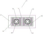
FIG. 3 is a schematic view of the internal structure of the heat dissipation base of the present invention;
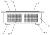
fig. 4 is a front view of the heat dissipation base of the present invention.
In the figure: 1-a power module body, 2-a heat dissipation base, 3-a power module fixing frame, 4-bolt holes, 5-a heat dissipation copper plate, 6-a heat conducting fin, 7-a partition plate, 8-a first heat dissipation fin, 9-a first heat pipe, 10-a first heat dissipation fan, 11-a second heat dissipation fin, 12-a second heat pipe, 13-a second heat dissipation fan, 14-a heat dissipation window, 15-a dust screen, 16-a support column and 17-an anti-skid block.
Detailed Description
The technical solution in the embodiments of the present invention will be clearly and completely described below with reference to the drawings in the embodiments of the present invention, and it is obvious that the described embodiments are only some embodiments of the present invention, rather than all embodiments, and all other embodiments obtained by a person of ordinary skill in the art without creative work belong to the protection scope of the present invention based on the embodiments of the present invention.
Referring to fig. 1-4, the present invention provides a technical solution:
a power module with a heat dissipation base comprises a power module body 1, wherein a heat dissipation base 2 is installed on the lower side of the power module body 1, a power module fixing frame 3 is fixedly installed on the upper side of the heat dissipation base 2, a bolt hole 4 is formed in the middle of the power module fixing frame 3, a heat dissipation copper plate 5 is fixedly installed in the middle of the upper side of the heat dissipation base 2, heat conducting fins 6 are fixedly installed on the upper side of the heat dissipation copper plate 5, a partition plate 7 is fixedly installed in the middle of the inner portion of the heat dissipation base 2, first heat dissipation fins 8 are fixedly installed in the inner portion of the heat dissipation base 2 and located on the left side of the partition plate 7, first heat pipes 9 are installed among the first heat dissipation fins 8 in a staggered mode, a first heat dissipation fan 10 is fixedly installed in the middle of the first heat dissipation fins 8, second heat dissipation fins 11 are fixedly installed in the inner portion of the, a second heat radiation fan 13 is fixedly mounted in the middle of the second heat radiation fin 11, a heat radiation window 14 is formed in the side face of the heat radiation base 2, a dustproof net 15 is fixedly mounted inside the heat radiation window 14, support columns 16 are symmetrically mounted on the lower side of the heat radiation base 2, and anti-skidding blocks 17 are fixedly mounted on the lower side of the support columns 16.
The utility model discloses work flow: during the use, put power module body 1 on heat dissipation base 2, later the bolt passes bolt hole 4 and screws up the nut and can install heat dissipation base 2 on power module body 1, can normally use after the installation finishes, in the use, the heat that power module body 1 produced loops through conducting strip 6, heat dissipation copper 5 reachs first heat pipe 9, second heat pipe 12, and through first heat pipe 9, second heat pipe 12 conduction is to first radiating fin 8, second radiating fin 11 finally dispels the heat fast under the effect of first radiator fan 10 and second radiator fan 13, with this effect that reaches the quick heat dissipation of circuit board body 1.
Although embodiments of the present invention have been shown and described, it will be appreciated by those skilled in the art that changes, modifications, substitutions and alterations can be made in these embodiments without departing from the principles and spirit of the invention, the scope of which is defined in the appended claims and their equivalents.
Claims (6)
1. The utility model provides a power module with heat dissipation base, includes power module body (1), its characterized in that: heat dissipation base (2) are installed to the downside of power module body (1), the upside fixed mounting of heat dissipation base (2) has the fixed frame of power module (3), the middle department of the fixed frame of power module (3) has seted up bolt hole (4), the upside middle fixed mounting of heat dissipation base (2) has heat dissipation copper (5), the upside fixed mounting of heat dissipation copper (5) has conducting strip (6), the inside middle fixed mounting of heat dissipation base (2) has baffle (7), the inside of heat dissipation base (2) and the left side fixed mounting who is located baffle (7) have first radiating fin (8), crisscross first heat pipe (9) of installing between first radiating fin (8), the middle fixed mounting of department of first radiating fin (8) has first radiating fan (10), the inside of heat dissipation base (2) and the right side fixed mounting that is located baffle (7) have second radiating fin (11) ) The heat dissipation structure comprises a first heat pipe (12), a second heat pipe (12) is installed between second heat dissipation fins (11) in a staggered mode, a second heat dissipation fan (13) is installed in the middle of the second heat dissipation fins (11), a heat dissipation window (14) is formed in the side face of a heat dissipation base (2), a dust screen (15) is fixedly installed inside the heat dissipation window (14), support columns (16) are symmetrically installed on the lower sides of the heat dissipation base (2), and anti-slip blocks (17) are fixedly installed on the lower sides of the support columns (16).
2. The power module with the heat dissipation base of claim 1, wherein: the power module body (1) is provided with mounting holes with the same size at positions corresponding to the bolt holes (4).
3. The power module with the heat dissipation base of claim 1, wherein: the heat conducting sheet (6) is made of heat conducting graphite sheets.
4. The power module with the heat dissipation base of claim 1, wherein: the upper sides of the first heat pipe (9) and the second heat pipe (12) are both in contact with the heat-radiating copper plate (5).
5. The power module with the heat dissipation base of claim 1, wherein: the first radiating fins (8) and the second radiating fins (11) are circumferentially distributed on the side faces of the first radiating fan (10) and the second radiating fan (13) respectively.
6. The power module with the heat dissipation base of claim 1, wherein: mounting grooves are formed in the joints of the first radiating fins (8), the second radiating fins (11) and the radiating base (2), and the first radiating fins (8) and the second radiating fins (11) are connected with the radiating base (2) through the mounting grooves.
Priority Applications (1)
| Application Number | Priority Date | Filing Date | Title |
|---|---|---|---|
| CN201921990969.2U CN210835993U (en) | 2019-11-18 | 2019-11-18 | Power module with heat dissipation base |
Applications Claiming Priority (1)
| Application Number | Priority Date | Filing Date | Title |
|---|---|---|---|
| CN201921990969.2U CN210835993U (en) | 2019-11-18 | 2019-11-18 | Power module with heat dissipation base |
Publications (1)
| Publication Number | Publication Date |
|---|---|
| CN210835993U true CN210835993U (en) | 2020-06-23 |
Family
ID=71262436
Family Applications (1)
| Application Number | Title | Priority Date | Filing Date |
|---|---|---|---|
| CN201921990969.2U Active CN210835993U (en) | 2019-11-18 | 2019-11-18 | Power module with heat dissipation base |
Country Status (1)
| Country | Link |
|---|---|
| CN (1) | CN210835993U (en) |
-
2019
- 2019-11-18 CN CN201921990969.2U patent/CN210835993U/en active Active
Similar Documents
| Publication | Publication Date | Title |
|---|---|---|
| TWI707624B (en) | Heat dissipation device for exteapolation module | |
| CN210835993U (en) | Power module with heat dissipation base | |
| CN210895329U (en) | Module structure for radiating in board | |
| CN210610161U (en) | Inverter device and heat dissipation device thereof | |
| CN210324071U (en) | CPU heat dissipation mounting structure for reinforcing server | |
| US6636423B2 (en) | Composite fins for heat sinks | |
| CN214376300U (en) | High-efficient hard disk cooling system | |
| CN216250709U (en) | Uniform temperature heat dissipation device | |
| CN215344761U (en) | Imaging device and electronic apparatus | |
| CN212910570U (en) | Heat dissipation type wave filter with air-cooled structure | |
| CN211063861U (en) | High-precision multilayer printed circuit board | |
| CN210610093U (en) | High-efficient heat dissipation type PCB circuit board | |
| CN113422575A (en) | Photovoltaic power station, power equipment and heat radiation structure thereof | |
| CN111556693A (en) | Radiator and installation composition structure thereof | |
| CN219181544U (en) | Switch for information engineering network | |
| CN215071033U (en) | Power distribution cabinet for mine | |
| CN216960655U (en) | Vehicle-mounted navigation host with heat dissipation function | |
| CN210899817U (en) | Circuit board module with high-efficiency heat dissipation | |
| CN220271853U (en) | External computer host heat abstractor | |
| CN212629061U (en) | Special high-efficient heat dissipation aluminium alloy of rack | |
| CN215450082U (en) | Host and terminal equipment | |
| CN220108151U (en) | Mute sound equipment power amplifier equipment | |
| CN218631732U (en) | Switch module based on PXI bus standard | |
| CN215897305U (en) | Power balancing device for electric equipment | |
| CN210295692U (en) | High temperature resistant intelligent display |
Legal Events
| Date | Code | Title | Description |
|---|---|---|---|
| GR01 | Patent grant | ||
| GR01 | Patent grant |