CN210779594U - an electrical protection device - Google Patents
an electrical protection device Download PDFInfo
- Publication number
- CN210779594U CN210779594U CN201922018714.6U CN201922018714U CN210779594U CN 210779594 U CN210779594 U CN 210779594U CN 201922018714 U CN201922018714 U CN 201922018714U CN 210779594 U CN210779594 U CN 210779594U
- Authority
- CN
- China
- Prior art keywords
- outer box
- protection device
- groups
- fixedly arranged
- inner plate
- Prior art date
- Legal status (The legal status is an assumption and is not a legal conclusion. Google has not performed a legal analysis and makes no representation as to the accuracy of the status listed.)
- Expired - Fee Related
Links
Images


Landscapes
- Patch Boards (AREA)
Abstract
本实用新型公开了一种电气保护装置,包括外箱和散热风扇,外箱的一侧内部固定设置有内板,内板与外箱的内壁形成通风管道,通过在外箱外侧壁设置散热风扇,并通过通风管道使空气通过内板底部的第二通气孔,进入外箱内部对电元器件进行散热,并将热量通过第一通气孔排出,在进行风扇散热时,风扇所带进来的灰尘和油污,会通过防尘海绵进行吸附,从而避免了传统的风扇散热会将灰尘和油污带进外箱内部,堆积在元器件的表面,影响元器件的本身的散热效果,当温度不高时,可以通过设置的散热孔,并配合第一通气孔形成空气自然情况下对流,并对元器件进行散热,设置的防护棚和避雨板也可以有效起到对外箱内部的电元器件起到避免受雨水进入的效果。
The utility model discloses an electrical protection device, comprising an outer box and a cooling fan. An inner plate is fixedly arranged inside one side of the outer box, and the inner plate and the inner wall of the outer box form a ventilation duct. And through the ventilation duct, the air passes through the second ventilation hole at the bottom of the inner plate, enters the outer box to dissipate heat from the electrical components, and discharges the heat through the first ventilation hole. The oil will be adsorbed by the dust-proof sponge, so as to avoid the traditional fan heat dissipation, which will bring dust and oil into the outer box and accumulate on the surface of the components, which will affect the heat dissipation effect of the components themselves. When the temperature is not high, The air can be naturally convectioned through the set heat dissipation holes and cooperate with the first ventilation holes to dissipate heat from the components. The set protective shed and rain shield can also effectively avoid the electrical components inside the outer box. Subject to the effect of rain entering.
Description
技术领域technical field
本实用新型属于电气保护技术领域,具体涉及一种电气保护装置。The utility model belongs to the technical field of electrical protection, in particular to an electrical protection device.
背景技术Background technique
电气是电能的生产、传输、分配、使用和电工装备制造等学科或工程领域的统称。是以电能、电气设备和电气技术为手段来创造、维持与改善限定空间和环境的一门科学,涵盖电能的转换、利用和研究三方面,包括基础理论、应用技术、设施设备等。目前,市面上的电气大多都通过配电柜来控制和分配,所以配电柜可以说是电气使用时的最重要核心,但是配电柜在长期的使用过程中,温度会越来越高,容易发生短路等电气事故,但是目前市场上配电柜的保护装置大多比较简单,不具备散热功能、部分具有散热功能的,在风扇长期的使用下,外界的灰尘、油污以及有害气体也会随之进入配电柜内,被电路板表面静电吸附,日积月累,对元器件、线路等有一定的腐蚀,同时影响其散热性。积聚的灰尘受潮后还会引发电路板高压部分的短路。配电柜工作时间越长,上述问题越突出,累积到一定程度时就会引发控制部分的突然故障,因此有必要对现有技术进行改进,以解决上述问题。Electricity is a general term for disciplines or engineering fields such as the production, transmission, distribution, use of electrical energy and the manufacture of electrical equipment. It is a science that creates, maintains and improves limited space and environment by means of electrical energy, electrical equipment and electrical technology, covering three aspects of electrical energy conversion, utilization and research, including basic theory, application technology, facilities and equipment. At present, most of the electricity on the market is controlled and distributed through the power distribution cabinet, so the power distribution cabinet can be said to be the most important core of electrical use, but the temperature of the power distribution cabinet will become higher and higher in the long-term use process. Electrical accidents such as short circuit are prone to occur, but most of the protection devices of power distribution cabinets on the market are relatively simple, do not have heat dissipation function, and some have heat dissipation function. Under the long-term use of the fan, the external dust, oil and harmful gases will also follow. When it enters the power distribution cabinet, it is electrostatically adsorbed on the surface of the circuit board. Over time, it will corrode components and lines, and at the same time affect its heat dissipation. The accumulated dust can also cause a short circuit in the high-voltage part of the circuit board when wet. The longer the working time of the power distribution cabinet, the more prominent the above-mentioned problems. When accumulated to a certain extent, it will cause a sudden failure of the control part. Therefore, it is necessary to improve the existing technology to solve the above-mentioned problems.
实用新型内容Utility model content
本实用新型的目的在于提供一种电气保护装置,以解决上述背景技术中提出的问题。The purpose of the present invention is to provide an electrical protection device to solve the above-mentioned problems in the background art.
为实现上述目的,本实用新型提供如下技术方案:一种电气保护装置,包括外箱和散热风扇,外箱的一侧内部固定设置有内板,内板与外箱的内壁形成通风管道,内板的一侧侧壁和外箱的底部固定设置有防尘海绵,外箱的一侧外壁固定设置有防护外框,防护外框的内部固定安装有散热风扇,内板的底部开设有若干组第二通气孔,外箱的顶端开设有若干组第一通气孔,外箱远离散热风扇的一侧开设有若干组散热孔,外箱的侧壁且位于散热孔的上方固定设置有避雨板,外箱的顶端两组固定设置有支撑杆,两组支撑杆的顶端固定设置有防护棚,外箱前端通过铰链连接有柜门,柜门的内侧面固定安装有温度传感器,柜门的外侧面固定安装有控制面板,外箱的内部且位于内板的一侧固定设置有若干组电器安装板。In order to achieve the above purpose, the utility model provides the following technical solutions: an electrical protection device, comprising an outer box and a cooling fan, one side of the outer box is fixedly provided with an inner plate, the inner plate and the inner wall of the outer box form a ventilation duct, One side wall of the board and the bottom of the outer box are fixed with dust-proof sponges, one side of the outer wall of the outer box is fixed with a protective outer frame, the inside of the protective outer frame is fixedly installed with a cooling fan, and the bottom of the inner plate is provided with several groups. For the second ventilation holes, the top of the outer box is provided with several groups of first ventilation holes, the side of the outer box away from the cooling fan is provided with several groups of cooling holes, and the side wall of the outer box is fixed above the cooling holes with a rain shield. , the top two groups of the outer box are fixed with support rods, the top of the two groups of support rods are fixed with a protective shed, the front end of the outer box is connected with a cabinet door through hinges, the inner side of the cabinet door is fixedly installed with a temperature sensor, and the outer side of the cabinet door is fixed with a temperature sensor. A control panel is fixedly installed on the side, and several groups of electrical installation boards are fixedly arranged inside the outer box and on one side of the inner panel.
进一步的,所述防护棚呈圆弧形设置,且所述防护棚的长度大于外箱的宽度,使防护棚能够更好避免外箱遭受雨水的影响。Further, the protective shed is arranged in an arc shape, and the length of the protective shed is greater than the width of the outer box, so that the protective shed can better prevent the outer box from being affected by rainwater.
进一步的,所述外箱的底部通过螺栓固定设置有四组移动轮,且所述移动轮为带有刹车装置的移动轮,便于整体装置的移动。Further, four groups of moving wheels are fixed on the bottom of the outer box by bolts, and the moving wheels are moving wheels with a braking device, which is convenient for the movement of the whole device.
进一步的,所述外箱上散热风扇安装外壁与通风管道互相贯通。Further, the outer wall where the cooling fan is installed on the outer box and the ventilation duct communicate with each other.
进一步的,所述柜门的外侧面固定安装拉手,方便打开柜门。Further, a handle is fixedly installed on the outer side of the cabinet door to facilitate opening the cabinet door.
进一步的,所述散热孔和避雨板均呈向下倾斜设置,避免雨水进入。Further, the heat dissipation holes and the rain shield are inclined downward to prevent rainwater from entering.
与现有技术相比,本实用新型的有益效果是:该一种电气保护装置,通过在外箱外侧壁设置散热风扇,并通过通风管道使空气通过内板底部的第二通气孔,进入外箱内部对电元器件进行散热,并将热量通过第一通气孔排出,在进行风扇散热时,风扇所带进来的灰尘和油污,会通过防尘海绵进行吸附,从而避免了传统的风扇散热会将灰尘和油污带进外箱内部,堆积在元器件的表面,影响元器件的本身的散热效果,在柜门上设置的温度传感器可以检测外箱内部的温度,当温度不高时,可以通过设置的散热孔,并配合第一通气孔形成空气自然情况下对流,并对元器件进行散热,设置的防护棚和避雨板也可以有效起到对外箱内部的电元器件起到避免受雨水进入的效果。Compared with the prior art, the beneficial effect of the present utility model is as follows: the electrical protection device, by arranging a cooling fan on the outer side wall of the outer box, and passing the air through the second ventilation hole at the bottom of the inner plate through the ventilation duct, enters the outer box. The electrical components are dissipated internally, and the heat is discharged through the first ventilation hole. When the fan is dissipating heat, the dust and oil brought in by the fan will be absorbed by the dust-proof sponge, thus avoiding the traditional fan heat dissipation. Dust and oil are brought into the outer box and accumulated on the surface of the components, affecting the heat dissipation effect of the components themselves. The temperature sensor set on the cabinet door can detect the temperature inside the outer box. When the temperature is not high, it can be set by setting The heat dissipation holes are combined with the first ventilation holes to form air convection under natural conditions, and the components are dissipated. The installed protective shed and rain shield can also effectively prevent the electrical components inside the outer box from entering the rainwater. Effect.
附图说明Description of drawings
附图用来提供对本实用新型的进一步理解,并且构成说明书的一部分,与本实用新型的实施例一起用于解释本实用新型,并不构成对本实用新型的限制。在附图中:The accompanying drawings are used to provide a further understanding of the present invention, and constitute a part of the specification, and are used to explain the present invention together with the embodiments of the present invention, and do not constitute a limitation to the present invention. In the attached image:
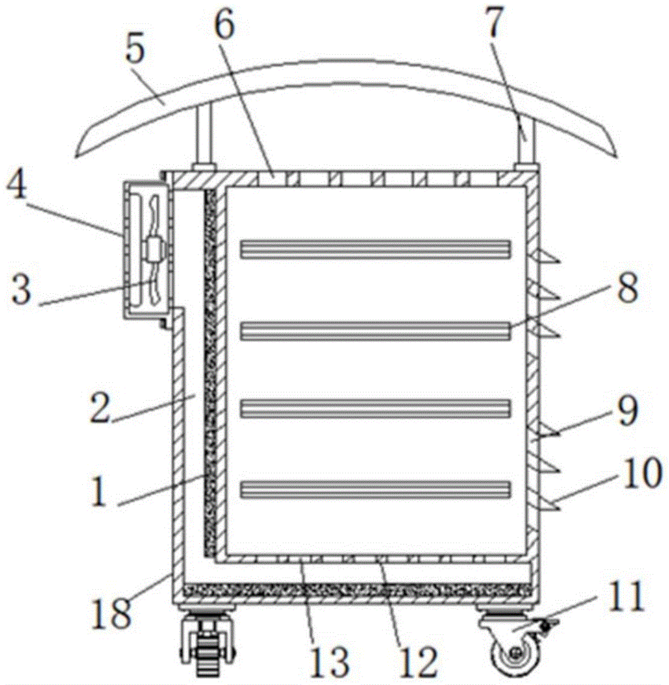
图1为本实用新型的整体内剖视图;Fig. 1 is the overall internal sectional view of the utility model;
图2为本实用新型的整体主视图;Fig. 2 is the overall front view of the utility model;
图3为本实用新型的整体内部视图。Figure 3 is an overall internal view of the present invention.
图中:1、防尘海绵;2、通风管道;3、散热风扇;4、防护外框;5、防护棚;6、第一通气孔;7、支撑杆;8、电器安装板;9、散热孔;10、避雨板;11、移动轮;12、内板;13、第二通气孔;14、柜门;15、控制面板;16、拉手;17、温度传感器;18、外箱。In the figure: 1. Dust-proof sponge; 2. Ventilation duct; 3. Cooling fan; 4. Protective frame; 5. Protective shed; 6. The first ventilation hole; 7. Support rod; 8. Electrical installation plate; 9. Heat dissipation hole; 10. Rain shield; 11. Moving wheel; 12. Inner plate; 13. Second ventilation hole; 14. Cabinet door; 15. Control panel; 16. Handle; 17. Temperature sensor; 18. Outer box.
具体实施方式Detailed ways
下面将结合本实用新型实施例中的附图,对本实用新型实施例中的技术方案进行清楚、完整地描述,显然,所描述的实施例仅仅是本实用新型一部分实施例,而不是全部的实施例。基于本实用新型中的实施例,本领域普通技术人员在没有做出创造性劳动前提下所获得的所有其他实施例,都属于本实用新型保护的范围。The technical solutions in the embodiments of the present utility model will be clearly and completely described below with reference to the accompanying drawings in the embodiments of the present utility model. Obviously, the described embodiments are only a part of the embodiments of the present utility model, rather than all the implementations. example. Based on the embodiments of the present invention, all other embodiments obtained by those of ordinary skill in the art without creative work fall within the protection scope of the present invention.
请参阅图1-3,本实用新型提供一种技术方案:一种电气保护装置,包括外箱18和散热风扇3,外箱18的一侧内部固定设置有内板12,内板12与外箱18的内壁形成通风管道2,内板12的一侧侧壁和外箱18的底部固定设置有防尘海绵1,外箱18的一侧外壁固定设置有防护外框4,防护外框4的内部固定安装有散热风扇3,内板12的底部开设有若干组第二通气孔13,外箱18的顶端开设有若干组第一通气孔6,外箱18远离散热风扇3的一侧开设有若干组散热孔9,外箱18的侧壁且位于散热孔9的上方固定设置有避雨板10,外箱18的顶端两组固定设置有支撑杆7,两组支撑杆7的顶端固定设置有防护棚5,外箱18前端通过铰链连接有柜门14,柜门14的内侧面固定安装有温度传感器17,温度传感器17的具体型号为SGMC-10-0-1-7,柜门14的外侧面固定安装有控制面板15,外箱18的内部且位于内板12的一侧固定设置有若干组电器安装板8。1-3, the present invention provides a technical solution: an electrical protection device, comprising an
如图1所示,防护棚5呈圆弧形设置,且防护棚5的长度大于外箱18的宽度,使防护棚5能够更好避免外箱18遭受雨水的影响。As shown in FIG. 1 , the
如图1所示,外箱18的底部通过螺栓固定设置有四组移动轮11,且移动轮11为带有刹车装置的移动轮11,便于整体装置的移动。As shown in FIG. 1 , four groups of moving
如图1所示,外箱18上散热风扇3安装外壁与通风管道2互相贯通。As shown in FIG. 1 , the outer wall on which the cooling
如图2所示,柜门14的外侧面固定安装拉手16,方便打开柜门14。As shown in FIG. 2 , the
如图1所示,散热孔9和避雨板10均呈向下倾斜设置,避免雨水进入。As shown in FIG. 1 , the
本实用新型的工作原理及使用流程:该一种电气保护装置设置的散热风扇3、温度传感器17和控制面板15之间互相电性连接,在使用时将元器件在外箱18内的安装板8上完成,然后关闭柜门14,并通过外箱18底部的移动轮11,将装置整体移动到适当的位置,根据柜门14内侧的设置的温度传感器17,可以检测外箱18内部的实时温度情况,并通过控制面板15显示出来,当观测到外箱18内部温度较高时,通过控制面板15使散热风扇启动,风扇将外部空气带进通风管道2,空气中的灰尘和油污,会吸附在防尘海绵1上,空气通过通风管道2和第二通气孔13进入外箱18内部,并将电元器件产生的热量带走,由第一通气孔6排出,实现对电元器件的散热,当外箱18内部温度不高时,由外箱18顶端开设第一通气孔6和散热孔9,可以使外部空气形成的自然的对流,对外箱18内部进行散热,设置的防护棚5和避雨板10可以避免雨水通过第一通气孔6和散热孔9进行外箱18内部,同时防护棚也可起到防晒作用,避免由外部原因造成外箱18内部温度过高。The working principle and use process of the present invention: the cooling
需要说明的是,在本文中,术语“上”、“下”、“内”、“外”“前端”、“后端”、“两端”、“一端”、“另一端”等指示的方位或位置关系为基于附图所示的方位或位置关系,仅是为了便于描述本实用新型和简化描述,而不是指示或暗示所指的装置或元件必须具有特定的方位、以特定的方位构造和操作,因此不能理解为对本实用新型的限制。It should be noted that in this document, the terms "upper", "lower", "inner", "outer", "front end", "rear end", "both ends", "one end", "the other end", etc. The orientation or positional relationship is based on the orientation or positional relationship shown in the accompanying drawings, which is only for the convenience of describing the present invention and simplifying the description, rather than indicating or implying that the referred device or element must have a specific orientation or be constructed in a specific orientation. and operation, so it should not be construed as a limitation of the present invention.
尽管已经示出和描述了本实用新型的实施例,对于本领域的普通技术人员而言,可以理解在不脱离本实用新型的原理和精神的情况下可以对这些实施例进行多种变化、修改、替换和变型,本实用新型的范围由所附权利要求及其等同物限定。Although the embodiments of the present invention have been shown and described, it will be understood by those skilled in the art that various changes and modifications can be made to these embodiments without departing from the principles and spirit of the present invention , alternatives and modifications, the scope of the present invention is defined by the appended claims and their equivalents.
Claims (6)
Priority Applications (1)
| Application Number | Priority Date | Filing Date | Title |
|---|---|---|---|
| CN201922018714.6U CN210779594U (en) | 2019-11-21 | 2019-11-21 | an electrical protection device |
Applications Claiming Priority (1)
| Application Number | Priority Date | Filing Date | Title |
|---|---|---|---|
| CN201922018714.6U CN210779594U (en) | 2019-11-21 | 2019-11-21 | an electrical protection device |
Publications (1)
| Publication Number | Publication Date |
|---|---|
| CN210779594U true CN210779594U (en) | 2020-06-16 |
Family
ID=71042262
Family Applications (1)
| Application Number | Title | Priority Date | Filing Date |
|---|---|---|---|
| CN201922018714.6U Expired - Fee Related CN210779594U (en) | 2019-11-21 | 2019-11-21 | an electrical protection device |
Country Status (1)
| Country | Link |
|---|---|
| CN (1) | CN210779594U (en) |
Cited By (2)
| Publication number | Priority date | Publication date | Assignee | Title |
|---|---|---|---|---|
| CN111711097A (en) * | 2020-06-23 | 2020-09-25 | 淮南万泰电气有限公司 | Inflatable looped netowrk cabinet |
| CN112993791A (en) * | 2021-04-10 | 2021-06-18 | 保定富阳电力科技有限公司 | Remote monitoring intelligent power distribution cabinet |
-
2019
- 2019-11-21 CN CN201922018714.6U patent/CN210779594U/en not_active Expired - Fee Related
Cited By (3)
| Publication number | Priority date | Publication date | Assignee | Title |
|---|---|---|---|---|
| CN111711097A (en) * | 2020-06-23 | 2020-09-25 | 淮南万泰电气有限公司 | Inflatable looped netowrk cabinet |
| CN111711097B (en) * | 2020-06-23 | 2024-06-04 | 淮南万泰电气有限公司 | Inflatable ring main unit |
| CN112993791A (en) * | 2021-04-10 | 2021-06-18 | 保定富阳电力科技有限公司 | Remote monitoring intelligent power distribution cabinet |
Similar Documents
| Publication | Publication Date | Title |
|---|---|---|
| CN206834576U (en) | A kind of Dustproof radiating electric power box | |
| CN207426499U (en) | A kind of high-tension switch cabinet of good heat dissipation effect | |
| CN210779594U (en) | an electrical protection device | |
| CN206293781U (en) | An electrical automation distribution cabinet | |
| CN210577282U (en) | Heat radiation structure of electric power distribution cabinet | |
| CN209747998U (en) | ammeter case with dampproofing function | |
| CN109004539B (en) | An outdoor windproof and waterproof switch cabinet of a substation | |
| CN220733280U (en) | Control cabinet capable of avoiding being affected with damp | |
| CN209964517U (en) | High-voltage electrical cabinet with heat abstractor | |
| CN111799683A (en) | A power distribution cabinet with noise reduction structure | |
| CN111613999A (en) | High-efficient heat sink is used to power equipment | |
| CN216750764U (en) | Power distribution cabinet with heat dissipation structure | |
| CN216312472U (en) | A power control box that facilitates heat dissipation and dehumidification | |
| CN206498112U (en) | A kind of outdoor use electric automatization distribution box | |
| CN206516916U (en) | A kind of electric power cabinet being easily installed | |
| CN206022934U (en) | A kind of intelligent power distribution cabinet of real-time Moistureproof dehumidification | |
| CN216773976U (en) | Electric box for high-rise civil buildings | |
| CN207753352U (en) | A kind of harmonic elimination compensating cabinet of easy access and heat dissipation | |
| CN209625133U (en) | A leakage-proof computer hardware case | |
| CN217405989U (en) | Interim block terminal that building site was used is built in room | |
| CN219499828U (en) | Electromechanical device heat abstractor for highway | |
| CN221767348U (en) | A temporary power distribution cabinet for construction sites | |
| CN223451979U (en) | An external anti-interference device for shortwave communication equipment | |
| CN218123998U (en) | Switch cabinet capable of preventing moisture and dehumidifying | |
| CN218828544U (en) | A dehumidification device for an electrical cabinet |
Legal Events
| Date | Code | Title | Description |
|---|---|---|---|
| GR01 | Patent grant | ||
| GR01 | Patent grant | ||
| CF01 | Termination of patent right due to non-payment of annual fee | ||
| CF01 | Termination of patent right due to non-payment of annual fee |
Granted publication date: 20200616 |