CN210577282U - Heat radiation structure of electric power distribution cabinet - Google Patents
Heat radiation structure of electric power distribution cabinet Download PDFInfo
- Publication number
- CN210577282U CN210577282U CN201921487169.9U CN201921487169U CN210577282U CN 210577282 U CN210577282 U CN 210577282U CN 201921487169 U CN201921487169 U CN 201921487169U CN 210577282 U CN210577282 U CN 210577282U
- Authority
- CN
- China
- Prior art keywords
- heat dissipation
- rectangular
- distribution cabinet
- filter screen
- heat
- Prior art date
- Legal status (The legal status is an assumption and is not a legal conclusion. Google has not performed a legal analysis and makes no representation as to the accuracy of the status listed.)
- Active
Links
Images
Abstract
The utility model discloses a heat radiation structure of electric power distribution cabinet, including the heat dissipation casing, the right-hand member both sides fixed mounting of heat dissipation casing has the rectangle baffle, the inside rectangular channel that has all been seted up in the upper and lower both sides of rectangle baffle, the inside fixed mounting of rectangular channel has compression spring, compression spring's other end fixedly connected with dog, the dog slides the flexible extension board of top fixed connection who sets up and the dog with the inside wall of rectangular channel, the inside first filter screen of fixed mounting of right-hand member of heat dissipation casing, the equal fixed mounting in four sides of first filter screen has fixing bolt, the inside of heat dissipation casing and the fixed radiating fin that sets up in left side that is located first filter screen, radiating fin's left side fixed mounting has heat transfer fan, heat transfer fan's left side end is equipped with the dust adsorption net. The utility model discloses a can be very convenient carry out fixed mounting and change, clear up to the heat dissipation casing is inside, effectively improve the radiating effect, convenient to use to the heat dissipation casing.
Description
Technical Field
The utility model belongs to the technical field of heat radiation structure, concretely relates to heat radiation structure of electric power distribution cabinet.
Background
At present, along with the use of low-voltage electrical equipment with load bigger and bigger, the capacity of switch board is also bigger and bigger, and calorific capacity is also very big, and the temperature has very big influence to the operating condition and the life of the electrical components in the switch board. The current switch board mainly reaches the heat dissipation purpose through set up the heat dissipation window on the panel all around, if the switch board can not in time dispel the heat, will make the electrical components in the cabinet can not normally work, can cause electrical components's damage even but to the switch board that capacious, inconvenient moreover to the inside clearance of heat radiation structure, easily cause the influence to the radiating effect. Therefore, the heat dissipation structure of the electrical power distribution cabinet convenient to disassemble and assemble is provided to solve the problems.
SUMMERY OF THE UTILITY MODEL
An object of the utility model is to provide an electric power distribution cabinet's heat radiation structure to solve the problem that proposes in the above-mentioned background art.
In order to achieve the above object, the utility model provides a following technical scheme: a heat dissipation structure of an electrical power distribution cabinet comprises a heat dissipation shell, rectangular baffles are fixedly mounted on two sides of the right end of the heat dissipation shell, rectangular grooves are formed in the upper side end and the lower side end of each rectangular baffle, compression springs are fixedly mounted in the rectangular grooves, stop blocks are fixedly connected to the other ends of the compression springs, the stop blocks are slidably arranged on the inner side walls of the rectangular grooves, telescopic support plates are fixedly connected to the top ends of the stop blocks, a first filter screen is fixedly mounted in the right end of the heat dissipation shell, fixing bolts are fixedly mounted on four side ends of the first filter screen, heat dissipation fins are fixedly arranged in the heat dissipation shell and located on the left side of the first filter screen, heat exchange fans are fixedly mounted on the left side ends of the heat exchange fans, dust adsorption nets are arranged at the left side ends of the heat exchange fans, and rectangular blocks are fixedly connected to the upper inner side walls, the inside draw-in groove of seting up with the upper and lower both ends looks adaptation of dust adsorption net of rectangular block, the left end of heat dissipation casing is fixed to be set up the air outlet, rectangular hole and the downthehole clearance fit of rectangular hole set up the rectangular cover board has been seted up on the positive surface of heat dissipation casing, the both sides end runs through and alternates in the inboard of Contraband templates about the rectangular cover board.
Preferably, the top end of the telescopic support plate is internally provided with a mounting hole.
This setting up the mounting hole, can carry out fixed mounting setting to the rectangle baffle.
Preferably, fixing bolt's the other end runs through first filter screen and extends to its left side fixedly connected with fixed block, the inside of fixed block is seted up with the screw hole of fixing bolt looks adaptation.
This setting fixed block and screw hole can be dismantled, install first filter screen through twisting fixing bolt.
Preferably, the radiating fins are uniformly and fixedly arranged on the supporting plate at equal intervals, and the upper end and the lower end of the supporting plate are connected with the inner side wall of the radiating shell.
This sets up the backup pad and can play fixed support effect to radiating fin, the convenient heat absorption.
Preferably, the Contraband template fixed mounting is in the front of heat dissipation casing and is located the left and right sides end of rectangle apron, and Contraband template's vertical direction evenly seted up three first screw holes of group.
The first threaded hole is arranged, and a screw can be installed in the first threaded hole, so that the rectangular cover plate can be fixed.
Preferably, the left side end and the right side end of the rectangular cover plate and the position corresponding to the first threaded hole are provided with circular holes with the same diameter as the first threaded hole.
The utility model discloses a technological effect and advantage: the heat dissipation structure of the electric power distribution cabinet can fixedly install the heat dissipation shell in the electric power distribution cabinet through the combined arrangement of the rectangular baffle, the rectangular groove, the compression spring, the stop block and the telescopic support plate; through the synergism of rectangle piece, fixing bolt, fixed block, Contraband template and first screw hole, what can be very convenient adsorbs net and rectangle apron to first filter screen, dust and assembles the use, and makes things convenient for the later stage to change the clearance, and the operation of being convenient for is used simple structure.
Drawings
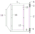
Fig. 1 is a schematic structural view of the present invention;
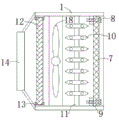
fig. 2 is a schematic view of the internal structure of the heat dissipation casing of the present invention;
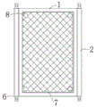
fig. 3 is a schematic view of the structure of the heat dissipation housing of the present invention.
In the figure: 1. a heat dissipating housing; 2. a rectangular baffle plate; 3. a rectangular groove; 4. a compression spring; 5. a stopper; 6. a telescopic support plate; 7. a first filter screen; 8. fixing the bolt; 9. a fixed block; 10. a heat dissipating fin; 11. a support plate; 12. a dust adsorbing net; 13. a rectangular block; 14. an air outlet; 15. a rectangular cover plate; 16. contraband a template; 17. a first threaded hole; 18. a heat exchange fan.
Detailed Description
The technical solutions in the embodiments of the present invention will be described clearly and completely with reference to the accompanying drawings in the embodiments of the present invention, and it is obvious that the described embodiments are only some embodiments of the present invention, not all embodiments. Based on the embodiments in the present invention, all other embodiments obtained by a person skilled in the art without creative work belong to the protection scope of the present invention.
The utility model provides a heat dissipation structure of an electrical power distribution cabinet as shown in figures 1-3, which comprises a heat dissipation shell 1, wherein rectangular baffles 2 are fixedly arranged at two sides of the right end of the heat dissipation shell 1, rectangular grooves 3 are respectively arranged at the inner parts of the upper and lower sides of the rectangular baffles 2, compression springs 4 are fixedly arranged in the rectangular grooves 3, the other ends of the compression springs 4 are fixedly connected with stoppers 5, the stoppers 5 are slidably arranged with the inner side wall of the rectangular grooves 3, the top ends of the stoppers 5 are fixedly connected with telescopic support plates 6, a first filter screen 7 is fixedly arranged at the inner part of the right end of the heat dissipation shell 1, fixing bolts 8 are fixedly arranged at the four sides of the first filter screen 7, heat dissipation fins 10 are fixedly arranged at the left side of the first filter screen 7 in the heat dissipation shell 1, and heat exchange fans 18 are fixedly arranged at the left sides of, the left side end of heat exchange fan 18 is equipped with dust and adsorbs net 12, on the upper and lower inside wall of heat dissipation casing 1 and with dust adsorption net 12 corresponding position fixedly connected with rectangular block 13, the inside draw-in groove of setting up with dust adsorption net 12's upper and lower both ends looks adaptation of rectangular block 13, the fixed air outlet 14 that sets up in left side of heat dissipation casing 1, rectangular hole and the downthehole clearance fit of rectangular hole set up rectangular cover plate 15 have been seted up on the positive surface of heat dissipation casing 1, both sides end runs through and alternates in the inboard of Contraband template 16 about rectangular cover plate 15.
Specifically, a mounting hole is formed in the top end of the telescopic support plate 6.
Specifically, fixing bolt 8's the other end runs through first filter screen 7 and extends to its left side fixedly connected with fixed block 9, the screw hole with 8 looks adaptations of fixing bolt is seted up to the inside of fixed block 9.
Specifically, the heat dissipation fins 10 are uniformly and fixedly mounted on the support plate 11 at equal intervals, and the upper end and the lower end of the support plate 11 are connected with the inner side wall of the heat dissipation shell 1.
Specifically, the Contraband shaped plates 16 are fixedly mounted on the front surface of the heat dissipation housing 1 and located at the left and right side ends of the rectangular cover plate 15, and three groups of first threaded holes 17 are uniformly formed in the Contraband shaped plates 16 in the vertical direction.
Specifically, circular holes having the same diameter as the first threaded holes 17 are formed at the left and right side ends of the rectangular cover plate 15 and at positions corresponding to the first threaded holes 17.
When the heat dissipation structure of the electric power distribution cabinet is used, the rectangular baffle 2 at the right end of the heat dissipation shell 1 is inserted into the electric power distribution cabinet by arranging the through hole matched with the heat dissipation shell 1 on the inner side wall of the electric power distribution cabinet, the telescopic support plate 6 can extend to the outer sides of the upper end and the lower end of the rectangular baffle 2 under the elastic action of the compression spring 4, the through hole corresponding to the mounting hole at the top end of the telescopic support plate 6 is arranged on the inner side wall of the electric power distribution cabinet, the rectangular baffle 2 can be fixedly mounted inside the electric power distribution cabinet by screwing the fastening screw, the heat exchange fan 18 is controlled to evacuate hot air generated by the cabinet body under the matching of the heat dissipation fin 10, dust inside the heat dissipation shell 1 can be filtered and adsorbed under the combination of the first filter screen 7 and the dust adsorption net 12, and hot air can be exhausted through the air outlet 14, thereby play and ventilate, dispel the heat the internal portion of cabinet, the later stage is through unscrewing Contraband template 16 and the screw of rectangle apron 15 installation, can dismantle rectangle apron 15 to the convenience is dismantled, is changed first filter screen 7 and dust adsorption net 12, is convenient for clear up easy operation inside heat dissipation casing 1.
Finally, it should be noted that: although the present invention has been described in detail with reference to the foregoing embodiments, it will be apparent to those skilled in the art that modifications and variations can be made in the embodiments or in part of the technical features of the embodiments without departing from the spirit and the scope of the invention.
Claims (6)
1. The utility model provides a heat radiation structure of electric switch board, includes heat dissipation casing (1), its characterized in that: the heat dissipation device is characterized in that rectangular baffles (2) are fixedly mounted on two sides of the right end of the heat dissipation shell (1), rectangular grooves (3) are formed in the upper side end and the lower side end of each rectangular baffle (2), compression springs (4) are fixedly mounted in the rectangular grooves (3), check blocks (5) are fixedly connected to the other ends of the compression springs (4), the check blocks (5) and the inner side walls of the rectangular grooves (3) are arranged in a sliding mode, telescopic support plates (6) are fixedly connected to the top ends of the check blocks (5), a first filter screen (7) is fixedly mounted in the right end of the heat dissipation shell (1), fixing bolts (8) are fixedly mounted at four side ends of the first filter screen (7), heat dissipation fins (10) are fixedly arranged in the heat dissipation shell (1) and located on the left side of the first filter screen (7), and heat exchange fans (18) are fixedly mounted at, the left side end of heat transfer fan (18) is equipped with dust and adsorbs net (12), on the upper and lower inside wall of heat dissipation casing (1) and with dust adsorption net (12) corresponding position fixedly connected with rectangular block (13), the draw-in groove of the upper and lower both ends looks adaptation with dust adsorption net (12) is seted up to rectangular block (13) inside, the left end of heat dissipation casing (1) is fixed to be set up air outlet (14), rectangular hole and the downthehole clearance fit of rectangular hole set up rectangle apron (15) have been seted up on the positive surface of heat dissipation casing (1), both sides run through and alternate in the inboard of Contraband template (16) about rectangle apron (15).
2. The heat dissipation structure of an electrical distribution cabinet according to claim 1, characterized in that: and a mounting hole is formed in the top end of the telescopic support plate (6).
3. The heat dissipation structure of an electrical distribution cabinet according to claim 1, characterized in that: the other end of fixing bolt (8) runs through first filter screen (7) and extends to its left side fixedly connected with fixed block (9), the screw hole with fixing bolt (8) looks adaptation is seted up to the inside of fixed block (9).
4. The heat dissipation structure of an electrical distribution cabinet according to claim 1, characterized in that: the heat dissipation shell is characterized in that the heat dissipation fins (10) are uniformly and fixedly arranged on the supporting plate (11) at equal intervals, and the upper end and the lower end of the supporting plate (11) are connected with the inner side wall of the heat dissipation shell (1).
5. The heat dissipation structure of an electrical distribution cabinet according to claim 1, characterized in that: the Contraband template (16) is fixedly arranged on the front face of the heat dissipation shell (1) and is positioned at the left side end and the right side end of the rectangular cover plate (15), and three groups of first threaded holes (17) are uniformly formed in the Contraband template (16) in the vertical direction.
6. The heat dissipation structure of an electrical distribution cabinet according to claim 5, wherein: and circular holes with the same diameter as the first threaded holes (17) are formed in the left side end and the right side end of the rectangular cover plate (15) and the positions corresponding to the first threaded holes (17).
Priority Applications (1)
| Application Number | Priority Date | Filing Date | Title |
|---|---|---|---|
| CN201921487169.9U CN210577282U (en) | 2019-09-09 | 2019-09-09 | Heat radiation structure of electric power distribution cabinet |
Applications Claiming Priority (1)
| Application Number | Priority Date | Filing Date | Title |
|---|---|---|---|
| CN201921487169.9U CN210577282U (en) | 2019-09-09 | 2019-09-09 | Heat radiation structure of electric power distribution cabinet |
Publications (1)
| Publication Number | Publication Date |
|---|---|
| CN210577282U true CN210577282U (en) | 2020-05-19 |
Family
ID=70638487
Family Applications (1)
| Application Number | Title | Priority Date | Filing Date |
|---|---|---|---|
| CN201921487169.9U Active CN210577282U (en) | 2019-09-09 | 2019-09-09 | Heat radiation structure of electric power distribution cabinet |
Country Status (1)
| Country | Link |
|---|---|
| CN (1) | CN210577282U (en) |
Cited By (2)
| Publication number | Priority date | Publication date | Assignee | Title |
|---|---|---|---|---|
| CN111786303A (en) * | 2020-08-04 | 2020-10-16 | 刘闪闪 | High-efficient radiating electrical equipment cabinet |
| CN112186588A (en) * | 2020-09-18 | 2021-01-05 | 安徽正日电气有限公司 | High-low voltage prefabricated box-type substation |
-
2019
- 2019-09-09 CN CN201921487169.9U patent/CN210577282U/en active Active
Cited By (2)
| Publication number | Priority date | Publication date | Assignee | Title |
|---|---|---|---|---|
| CN111786303A (en) * | 2020-08-04 | 2020-10-16 | 刘闪闪 | High-efficient radiating electrical equipment cabinet |
| CN112186588A (en) * | 2020-09-18 | 2021-01-05 | 安徽正日电气有限公司 | High-low voltage prefabricated box-type substation |
Similar Documents
| Publication | Publication Date | Title |
|---|---|---|
| CN210577282U (en) | Heat radiation structure of electric power distribution cabinet | |
| CN210137102U (en) | Assembled switch board | |
| CN213818549U (en) | Frequency converter with good heat dissipation performance | |
| CN208752566U (en) | A kind of heat sink for computer | |
| CN205159868U (en) | Low -voltage cabinet structure | |
| CN109286328A (en) | A kind of power supply adaptor cooling stand | |
| CN111613999A (en) | High-efficient heat sink is used to power equipment | |
| CN217019622U (en) | Guide rail protection cover for numerical control machine tool | |
| CN210779594U (en) | Electric protection device | |
| CN210959261U (en) | Integrated form magnetic suspension switch board structure | |
| CN213210928U (en) | Computer machine case with dustproof function | |
| CN210181516U (en) | Computer with internal circuit board having waterproof structure design | |
| CN211716841U (en) | Outdoor cabinet air conditioner with dustproof function | |
| CN208460670U (en) | A kind of relay with radiator structure | |
| CN211128778U (en) | Communication equipment heat dissipation mechanism easy to disassemble and assemble | |
| CN216699284U (en) | Building electrical control cabinet | |
| CN220066494U (en) | High-voltage board for equipment circuit control | |
| CN214204508U (en) | Solar energy household power generation cabinet convenient to move | |
| CN214586735U (en) | Fixing device with adjustable heat dissipation strength for computer hardware | |
| CN218887918U (en) | Mechanical equipment matching electric control cabinet | |
| CN215344212U (en) | Motor protective housing that radiating effect is good | |
| CN204304765U (en) | Medium voltage converter cabinet power cell | |
| CN220209784U (en) | Power distribution cabinet heat abstractor | |
| CN218649083U (en) | Novel distribution transformer terminal | |
| CN208239963U (en) | A kind of industrial computer radiator |
Legal Events
| Date | Code | Title | Description |
|---|---|---|---|
| GR01 | Patent grant | ||
| GR01 | Patent grant |