CN210778046U - Cable core stranding device - Google Patents
Cable core stranding device Download PDFInfo
- Publication number
- CN210778046U CN210778046U CN201922388708.XU CN201922388708U CN210778046U CN 210778046 U CN210778046 U CN 210778046U CN 201922388708 U CN201922388708 U CN 201922388708U CN 210778046 U CN210778046 U CN 210778046U
- Authority
- CN
- China
- Prior art keywords
- fixing
- base
- stranded conductor
- cable core
- fixed
- Prior art date
- Legal status (The legal status is an assumption and is not a legal conclusion. Google has not performed a legal analysis and makes no representation as to the accuracy of the status listed.)
- Active
Links
- WABPQHHGFIMREM-UHFFFAOYSA-N lead(0) Chemical compound [Pb] WABPQHHGFIMREM-UHFFFAOYSA-N 0.000 claims abstract description 14
- 230000005540 biological transmission Effects 0.000 claims abstract description 4
- 230000002093 peripheral effect Effects 0.000 claims abstract description 3
- 239000004020 conductor Substances 0.000 abstract description 29
- 235000017166 Bambusa arundinacea Nutrition 0.000 abstract description 9
- 235000017491 Bambusa tulda Nutrition 0.000 abstract description 9
- 241001330002 Bambuseae Species 0.000 abstract description 9
- 235000015334 Phyllostachys viridis Nutrition 0.000 abstract description 9
- 239000011425 bamboo Substances 0.000 abstract description 9
- 230000017105 transposition Effects 0.000 abstract description 5
- 238000009434 installation Methods 0.000 abstract description 3
- 238000010586 diagram Methods 0.000 description 3
- 238000004804 winding Methods 0.000 description 3
- 241000258920 Chilopoda Species 0.000 description 1
- 244000309464 bull Species 0.000 description 1
- 238000006073 displacement reaction Methods 0.000 description 1
- 239000004744 fabric Substances 0.000 description 1
- 238000004519 manufacturing process Methods 0.000 description 1
- 238000000034 method Methods 0.000 description 1
- 238000005192 partition Methods 0.000 description 1
Images


Abstract
The utility model discloses a cable core stranded conductor device, the on-line screen storage device comprises a base, left end position is fixed with the bearing plate on the base, and right side intermediate position is equipped with fixed section of thick bamboo on the bearing plate, and the peripheral position that the right side corresponds fixed section of thick bamboo on the bearing plate evenly is equipped with line section of thick bamboo fixed establishment, the right side position of fixed section of thick bamboo on the base is equipped with the stranded conductor dish, and stranded conductor dish suit is fixed in on the bearing of the bearing frame of installation on the base, lean on right end position to install the motor on the base, the motor passes through the belt and is connected with the transmission of stranded conductor dish, the through-hole has evenly been seted up on the stranded conductor dish, has worn the lead wire pole in the through-. The utility model provides a cable core stranded conductor device, the structure sets up ingeniously, and is rationally distributed, rotates through the stranded conductor dish and comes the wire transposition on cable center line, and at the during operation, noise at work is littleer, and the whipping vibration range of equipment is littleer, has promoted workman's operational environment comfort level.
Description
Technical Field
The utility model relates to a cable manufacture equipment technical field specifically is a cable core stranded conductor device.
Background
The cable is generally a rope-like cable formed by twisting several or several groups of wires (at least two in each group), each group of wires are insulated from each other and usually twisted around a center, and the whole outer surface is coated with a highly-insulated covering layer; in the process of processing the cable, a plurality of wires are twisted into a thicker wire by a twisting machine, and then the insulating cloth is wound on the outer side of the thicker cable by a wrapping machine.
The existing stranding machine often needs a wire barrel wound with wires to rotate along with the machine when stranding, each wire is stranded on a central line through rotation, the power requirement for rotation of the machine is higher, the fixation requirement for the wire barrel is high during rotation, the wire barrel is easy to fall off or the wires are easy to displace, normal stranding operation is influenced, and therefore a cable core stranding device is provided.
SUMMERY OF THE UTILITY MODEL
An object of the utility model is to provide a cable core stranded conductor device to solve the problem that proposes in the above-mentioned background art.
In order to achieve the above object, the utility model provides a following technical scheme:
the utility model provides a cable core stranded conductor device, includes the base, left end position is fixed with the bearing plate on the base, and right side intermediate position is equipped with fixed section of thick bamboo on the bearing plate, and the peripheral position that the right side corresponds fixed section of thick bamboo on the bearing plate evenly is equipped with wire barrel fixed establishment, the right side position of fixed section of thick bamboo on the base is equipped with the stranded conductor dish, and stranded conductor dish suit is fixed in on the bearing of the bearing bracket of installation on the base, lean on right end position to install the motor on the base, the motor passes through the belt and is connected with the transmission of stranded conductor dish, the through-hole has evenly been seted up on the stranded conductor dish, has worn the lead wire pole in the through-hole, and in the bottom of lead wire pole stretched into the stranded conductor dish, the top was located the stranded conductor dish outside, and the bottom position in the stranded conductor dish has seted up the lead wire hole.
As a further aspect of the present invention: and a fixing block is arranged on the outer side of the wire twisting disc corresponding to the through hole, and a fastening bolt for fixing the lead rod is arranged on the fixing block.
As a further aspect of the present invention: the middle of the upper fixing barrel corresponding to the position of each wire barrel fixing mechanism is provided with a spring telescopic rod, and the top of the spring telescopic rod is provided with a threading pipe.
As a further aspect of the present invention: and a fixed ring frame is arranged on the fixed cylinder close to the right end, and the fixed ring frame is uniformly connected with a wire poking rod.
As a further aspect of the present invention: the wire barrel fixing mechanism comprises a first fixing plate and a second fixing plate which are fixed on a bearing plate, a short rod is installed on the first fixing plate towards one side of the second fixing plate, a threaded rod is arranged on the second fixing plate corresponding to the short rod, the threaded rod is screwed in threaded holes formed in the second fixing plate and a convex block, and a rotating rod connected with the threaded rod is arranged at the rear end of the second fixing plate.
As a further aspect of the present invention: the fixed cylinder is provided with a straightening mechanism at the upper right end, the straightening mechanism comprises a straightening cylinder arranged on the fixed cylinder through a fixing plate, a straight hole is formed in the straightening cylinder, and arc-shaped openings are formed in two ends of the straight hole respectively.
Compared with the prior art, the utility model has the advantages of following several aspects:
the utility model discloses in, around the bobbin direct mount that has the wire on the fixed plate, when carrying out the stranded conductor, the bobbin does not rotate along with the stranded conductor dish, rotates by the stranded conductor dish and twists the wire spiral on the cable center line to centipede the pivoted power requirement greatly, the bobbin is no longer rotated along with the device simultaneously, has just also avoided the wire displacement to throw when rotating, makes the crooked condition of winding on equipment even of wire take place.
The utility model discloses in, rotate through the stranded conductor dish and come the wire transposition on the cable center line, at the during operation, noise at work is littleer, and the whipping vibration range of equipment is littleer, has promoted workman's operational environment comfort level.
The utility model discloses in, the wire lead dish moves the wire into then along with the rotation of stranded conductor dish and strand on the central line through the pin hole on the pin lead, and the pin lead is fixed by fastening bolt, when carrying out the stranded conductor, and the central line in different line footpaths can freely be adjusted through the length of adjusting the pin lead and stretching into the stranded conductor dish to can adapt to the cable strands of different thicknesses, it is nimble convenient to use.
Drawings
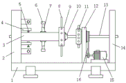
Fig. 1 is a top view of a cable core stranding device.
Fig. 2 is a schematic diagram of a structure of a cable core stranding device.
Fig. 3 is a schematic diagram of connection between an antenna and a machine body in a cable core twisting device.
Fig. 4 is a system modularization block diagram of a cable core stranding device.
In the figure: 1. a base; 2. a bearing plate; 3. a fixed cylinder; 4. a first fixing plate; 5. a short bar; 6. a threading tube; 7. a spring telescopic rod; 8. a wire poking rod; 9. fixing a ring frame; 10. a straightening mechanism; 11. a wire stranding disc; 12. a bearing bracket; 13. a cable centerline; 14. a partition plate; 15. a motor; 16. a belt; 17. a second fixing plate; 18. a bump; 19. a threaded rod; 20. a threaded hole; 21. a rotating rod; 22. a straightening cylinder; 23. a fixing sheet; 24. an arc-shaped opening; 25. a straight hole; 26. a wire-guiding rod; 27. a fixed block; 28. fastening a bolt; 29. a through hole; 30. and a lead hole.
Detailed Description
In order to make the objects, technical solutions and advantages of the present invention more clearly understood, the present invention is further described in detail below with reference to the accompanying drawings and embodiments. It should be understood that the specific embodiments described herein are for purposes of illustration only and are not intended to limit the invention.
In the description of the present invention, it should be noted that the terms "center", "upper", "lower", "left", "right", "vertical", "horizontal", "inner", "outer", and the like indicate orientations or positional relationships based on the orientations or positional relationships shown in the drawings, and are only for convenience of description and simplification of description, but do not indicate or imply that the device or element referred to must have a specific orientation, be constructed and operated in a specific orientation, and thus, should not be construed as limiting the present invention; the terms "first", "second" and "first" are used for descriptive purposes only and are not to be construed as indicating or implying relative importance; furthermore, unless expressly stated or limited otherwise, the terms "mounted," "connected," and "connected" are to be construed broadly, as they may be fixedly connected, detachably connected, or integrally connected, for example; can be mechanically or electrically connected; they may be connected directly or indirectly through intervening media, or they may be interconnected between two elements. The specific meaning of the above terms in the present invention can be understood in specific cases to those skilled in the art.
Please refer to fig. 1-4, a cable core wire twisting device, which comprises a base 1, a bearing plate 2 is fixed at the left end of the base 1, a fixing cylinder 3 is arranged at the middle position of the right side of the bearing plate 2, a wire cylinder fixing mechanism is uniformly arranged at the periphery of the bearing plate 2 corresponding to the fixing cylinder 3 at the right side, the wire cylinder fixing mechanism comprises a first fixing plate 4 and a second fixing plate 17 fixed on the bearing plate 2, a short rod 5 is arranged on the first fixing plate 4 facing one side of the second fixing plate 17, a threaded rod 19 is arranged on the second fixing plate 17 corresponding to the short rod 5, the threaded rod 19 is screwed into threaded holes 20 formed in the second fixing plate 17 and a convex block 18, and a rotating rod 21 connected with the threaded rod 19 is arranged at the rear end of the second fixing plate 17.
The middle of going up of a fixed cylinder 3 corresponds every bobbin fixed establishment position and is equipped with spring telescopic link 7, and spring telescopic link 7 top position is installed through the threading pipe 6, be close to right-hand member position on the fixed cylinder 3 and install retainer 9, evenly be connected with wire poking rod 8 on retainer 9, the right side position of a fixed cylinder 3 is equipped with cable reel 11 on the base 1, and on the bearing of the bearing frame 12 of installation on base 1 was fixed in to cable reel 11 suit, close to right end position on the base 1 and install motor 15, motor 15 was connected with cable reel 11 transmission through belt 16, and right-hand member position is connected with baffle 14 on the base 1, and in cable central line 13 penetrated fixed cylinder 3 from bearing plate 2, passed cable reel 11 and worn out from baffle 14, right-hand member position was equipped with straightening mechanism 10 on the fixed cylinder 3.
The utility model discloses a theory of operation is: the utility model provides a cable core stranded conductor device, the structure sets up ingeniously, and the overall arrangement is reasonable, penetrate cable central line 13 from the left end into a fixed cylinder 3 before using, wear out from the straight hole 25 of a straightening cylinder 22, pass from stranded conductor dish 11 again and wear out from baffle 14, pull to the admission machine, then will twine one end cover of wire line section of thick bamboo that needs the transposition on quarter butt 5, rethread bull stick 21 with threaded rod 19 inside propelling movement make it stretch into the line section of thick bamboo and fix, then move the wire head out and pass through threading pipe 6, dial the line pole 8 in proper order, pass from the pin hole 30 of pin 26 and wind on cable central line 13, pull cable central line 13 by the admission machine and move when carrying out the stranded conductor, open motor 15, motor 15 drives stranded conductor dish 11 through belt 16 and rotates, when stranded conductor rotates, the wire transposition is on cable central line 13, the cable that the transposition finishes is pulled by the admission machine and is received, meanwhile, the wire barrel is driven to pull out the non-twisted wires, the twisted cables are matched with the non-twisted wires in a winding and unwinding mode, and the wires are twisted on the central wire by the rotation of the take-up reel, so that the problem of winding of the wires is solved.
Although the preferred embodiments of the present patent have been described in detail, the present patent is not limited to the above embodiments, and various changes can be made without departing from the spirit of the present patent within the knowledge of those skilled in the art.
Claims (6)
1. A cable core stranding device comprises a base (1) and is characterized in that a bearing plate (2) is fixed at the left end of the base (1), a fixing barrel (3) is arranged at the middle position of the right side of the bearing plate (2), a wire barrel fixing mechanism is uniformly arranged at the right side of the bearing plate (2) corresponding to the peripheral position of the fixing barrel (3), a stranding disk (11) is arranged at the right side of the fixing barrel (3) on the base (1), the stranding disk (11) is fixedly sleeved on a bearing of a bearing frame (12) installed on the base (1), a motor (15) is installed at the position close to the right end of the base (1), the motor (15) is in transmission connection with the stranding disk (11) through a belt (16), through holes (29) are uniformly formed in the stranding disk (11), lead rods (26) penetrate through the through holes (29), and the bottom ends of the lead rods (26) extend into the stranding disk (11), the top is located the capstan winch (11) outside, and lead wire hole (30) have been seted up to the bottom position in capstan winch (11) on lead wire pole (26), and right-hand member position is connected with baffle (14) on base (1), and cable center line (13) are worn out from baffle (14) again in bearing plate (2) penetrate fixed cylinder (3), pass capstan winch (11).
2. The cable core stranding device according to claim 1, characterized in that a fixing block (27) is mounted on the outer side of the stranding disc (11) corresponding to the through hole (29), and a fastening bolt (28) for fixing the lead rod (26) is arranged on the fixing block (27).
3. The cable core stranding device according to claim 1, wherein a spring telescopic rod (7) is arranged in the middle of the fixing barrel (3) corresponding to each wire barrel fixing mechanism, and a threading pipe (6) is mounted at the top of the spring telescopic rod (7).
4. The cable core stranding device according to claim 3, wherein a fixing ring frame (9) is mounted on the fixing cylinder (3) close to the right end, and a wire poking rod (8) is uniformly connected to the fixing ring frame (9).
5. The cable core stranding device according to claim 1, wherein the bobbin fixing mechanism comprises a first fixing plate (4) and a second fixing plate (17) which are fixed on the bearing plate (2), a short rod (5) is installed on one side, facing the second fixing plate (17), of the first fixing plate (4), a threaded rod (19) is arranged on the second fixing plate (17) corresponding to the position of the short rod (5), the threaded rod (19) is screwed in threaded holes (20) formed in the second fixing plate (17) and the protruding block (18), and a rotating rod (21) connected with the threaded rod (19) is arranged at the rear end of the second fixing plate (17).
6. The cable core stranding device according to any one of claims 1 to 5, characterized in that a straightening mechanism (10) is arranged at a right end position on the fixed cylinder (3), the straightening mechanism (10) includes a straightening cylinder (22) mounted on the fixed cylinder (3) through a fixing piece (23), a straight hole (25) is formed in the straightening cylinder (22), and arc-shaped openings (24) are respectively formed at two ends of the straight hole (25).
Priority Applications (1)
| Application Number | Priority Date | Filing Date | Title |
|---|---|---|---|
| CN201922388708.XU CN210778046U (en) | 2019-12-27 | 2019-12-27 | Cable core stranding device |
Applications Claiming Priority (1)
| Application Number | Priority Date | Filing Date | Title |
|---|---|---|---|
| CN201922388708.XU CN210778046U (en) | 2019-12-27 | 2019-12-27 | Cable core stranding device |
Publications (1)
| Publication Number | Publication Date |
|---|---|
| CN210778046U true CN210778046U (en) | 2020-06-16 |
Family
ID=71044335
Family Applications (1)
| Application Number | Title | Priority Date | Filing Date |
|---|---|---|---|
| CN201922388708.XU Active CN210778046U (en) | 2019-12-27 | 2019-12-27 | Cable core stranding device |
Country Status (1)
| Country | Link |
|---|---|
| CN (1) | CN210778046U (en) |
Cited By (2)
| Publication number | Priority date | Publication date | Assignee | Title |
|---|---|---|---|---|
| CN114283997A (en) * | 2021-12-13 | 2022-04-05 | 重庆智荟数创科技有限公司 | Twisted cable and method for manufacturing same |
| CN117316535A (en) * | 2023-10-25 | 2023-12-29 | 广东顺德安连德电子科技有限公司 | Cable stranded wire device suitable for production of cables with different specifications and use method thereof |
-
2019
- 2019-12-27 CN CN201922388708.XU patent/CN210778046U/en active Active
Cited By (3)
| Publication number | Priority date | Publication date | Assignee | Title |
|---|---|---|---|---|
| CN114283997A (en) * | 2021-12-13 | 2022-04-05 | 重庆智荟数创科技有限公司 | Twisted cable and method for manufacturing same |
| CN114283997B (en) * | 2021-12-13 | 2024-01-02 | 国网甘肃省电力公司金昌供电公司 | Twisting device for cable and using method thereof |
| CN117316535A (en) * | 2023-10-25 | 2023-12-29 | 广东顺德安连德电子科技有限公司 | Cable stranded wire device suitable for production of cables with different specifications and use method thereof |
Similar Documents
| Publication | Publication Date | Title |
|---|---|---|
| CN210778046U (en) | Cable core stranding device | |
| CN213459224U (en) | Pipe stranding machine for cable production | |
| CN203351296U (en) | Double single-wire non-twist pair twister | |
| CN212152919U (en) | High-speed stranding machine for super-compact surface galvanized steel strand | |
| CN214421967U (en) | Yarn doubling device for jean fabric textile | |
| CN211699836U (en) | Frame winch | |
| CN210245153U (en) | A transposition stranding equipment for cable conductor | |
| CN217640801U (en) | Electric wire and cable weaving device | |
| CN117038210A (en) | Cable cage winch | |
| CN216526434U (en) | Optical cable stranding device for special optical cable | |
| CN116313294A (en) | Cable stranding machine | |
| CN205881578U (en) | Frame -type wire twisting machine | |
| CN209674927U (en) | A kind of flat elevator traveling cable | |
| CN212740144U (en) | Processing cable take-up device | |
| CN104934147B (en) | Wire winding arrangement | |
| CN209591665U (en) | A kind of four times of stranding machines | |
| CN218232674U (en) | Tennis racket line is with 5 strander s | |
| CN217444160U (en) | Novel fork-type wire stranding machine for cable processing | |
| CN209168758U (en) | A kind of copper clad aluminum stranded wire | |
| CN219759286U (en) | Frame type stranding machine for cable preparation | |
| CN210039790U (en) | Cable aluminum sheath wrapping machine | |
| CN117012461B (en) | Twisting and winding integrated machine for wire and cable production | |
| CN110931175A (en) | Cage-disc combined stranding equipment and cabling method | |
| CN216902386U (en) | Novel high-speed cable-former capable of pre-twisting without stopping | |
| CN218100806U (en) | Wire stranding device for wire processing |
Legal Events
| Date | Code | Title | Description |
|---|---|---|---|
| GR01 | Patent grant | ||
| GR01 | Patent grant | ||
| PE01 | Entry into force of the registration of the contract for pledge of patent right |
Denomination of utility model: A cable core twisted wire device Effective date of registration: 20231121 Granted publication date: 20200616 Pledgee: Hebei Bank Co.,Ltd. Renqiu Branch Pledgor: Zhongxin Cable Co.,Ltd. Registration number: Y2023980066913 |
|
| PE01 | Entry into force of the registration of the contract for pledge of patent right |