CN210705825U - Screw rod mould - Google Patents
Screw rod mould Download PDFInfo
- Publication number
- CN210705825U CN210705825U CN201921170976.8U CN201921170976U CN210705825U CN 210705825 U CN210705825 U CN 210705825U CN 201921170976 U CN201921170976 U CN 201921170976U CN 210705825 U CN210705825 U CN 210705825U
- Authority
- CN
- China
- Prior art keywords
- mould
- pulling mechanism
- block
- slider
- side core
- Prior art date
- Legal status (The legal status is an assumption and is not a legal conclusion. Google has not performed a legal analysis and makes no representation as to the accuracy of the status listed.)
- Active
Links
Images



Landscapes
- Moulds For Moulding Plastics Or The Like (AREA)
Abstract
The utility model discloses a hob mould, including last mould, lower mould and side core pulling mechanism, the both ends at last mould and lower mould are fixed respectively to the side core pulling mechanism, the inside hardware that is provided with of lower mould, this hob mould compares in traditional machining play hob, the cycle of injection mold production is tens seconds, its fashioned efficiency is higher and the process is automatic, and will exceed machining in material utilization, machining can produce a lot of waste materials and can not recycle, and injection moulding production can the secondary melt material recycle, and hardware location can be solved completely to this structure to solve mould volume production problem.
Description
Technical Field
The utility model relates to an injection mold technical field specifically is a hob mould.
Background
An injection mold is a tool for producing plastic products; and is also a tool for giving the plastic product complete structure and accurate dimension. Injection molding is a process used to mass produce parts of some complex shapes. Specifically, the plastic melted by heating is injected into a mold cavity from an injection molding machine at high pressure, and a formed product is obtained after cooling and solidification.
The existing plastic screw rod is usually machined, but the machining has the problems of low efficiency, low material utilization rate and the like. To this end, we propose a screw rod die.
SUMMERY OF THE UTILITY MODEL
An object of the utility model is to provide a hob mould to solve the problem that proposes among the above-mentioned background art.
In order to achieve the above object, the utility model provides a following technical scheme: the utility model provides a hob mould, includes mould, lower mould and side core pulling mechanism, the both ends at last mould and lower mould are fixed respectively to the side core pulling mechanism, the inside hardware that is provided with of lower mould.
Preferably, the side core-pulling mechanism comprises a first side core-pulling mechanism and a second side core-pulling mechanism, the first side core-pulling mechanism is fixedly connected with one end of the lower die, and the second side core-pulling mechanism is fixedly connected with one end of the lower die, far away from the first side core-pulling mechanism.
Preferably, the first side is loosed core and is included first hydro-cylinder, first slider and slide wedge, lower mould upper surface fixed mounting has first guide block, and first guide block is provided with two sets ofly, first slider lower surface and lower mould upper surface sliding connection, first slider both sides upper surface and first guide block lower surface sliding connection, the side surface fixed mounting of first hydro-cylinder and lower mould, the output and the first slider joint of first hydro-cylinder, the upper surface of slide wedge and the lower fixed mounting of last mould, the lower surface and the first slider sliding connection of slide wedge.
Preferably, the second side is loosed core including installation piece, second hydro-cylinder and stopper, the one end fixed mounting that first guide block was kept away from to the lower mould has the second guide block, the surface of installation piece and the lower surface sliding connection of lower mould upper surface and second guide block, the fixed surface installation of stopper lower mould, second hydro-cylinder and stopper fixed mounting, second hydro-cylinder and installation piece joint.
Preferably, the mounting block is fixedly provided with a second sliding block.
Compared with the prior art, the beneficial effects of the utility model are that:
1. the utility model discloses compare in traditional machining goes out the hob, the cycle of injection mold production is tens seconds, and its fashioned efficiency is higher and the process is automatic.
2. The utility model discloses with injection mold production hob will exceed machining in material utilization ratio, machining can produce a lot of waste materials and can not recycle, and injection molding production can the secondary melt the material and recycle.
Drawings
FIG. 1 is a schematic view of the upper mold structure of the present invention;
FIG. 2 is a schematic view of the lower mold structure of the present invention;
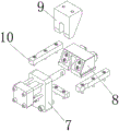
FIG. 3 is a schematic structural diagram of the core-pulling mechanism at the side;
FIG. 4 is a first side core-pulling exploded view;
FIG. 5 is a second side core back exploded view.
In the figure: 1-upper mould; 2-lower mould; 3-side core-pulling mechanism; 4-hardware; 5, core pulling at the first side; 6-second side core pulling; 7-a first oil cylinder; 8-a first slider; 9-a wedge; 10-a first guide block; 11-a mounting block; 12-a second oil cylinder; 13-a limiting block; 14-a second guide block; 15-second slider.
Detailed Description
The technical solutions in the embodiments of the present invention will be described clearly and completely with reference to the accompanying drawings in the embodiments of the present invention, and it is obvious that the described embodiments are only some embodiments of the present invention, not all embodiments. Based on the embodiments in the present invention, all other embodiments obtained by a person skilled in the art without creative work belong to the protection scope of the present invention.
Referring to fig. 1-5, the present invention provides a technical solution: the utility model provides a hob mould, includes mould 1, lower mould 2 and side core pulling mechanism 3, because this product is the plastic bag hardware, need put into injection moulding behind the hardware on the mould during moulding plastics, the difficult point of mould lies in the location problem of hardware on the mould, and this design utilizes the hardware to block from the step in area earlier under the mould die sinking state and realizes first location, then carries out the secondary through side core pulling mechanism 3 and fixes, then accomplishes injection moulding, side core pulling mechanism 3 fixes respectively at the both ends of last mould 1 and lower mould 2, 2 inside hardware 4 that are provided with of lower mould, the shaping is accomplished as the core to hardware 4.
The side core-pulling mechanism 3 comprises a first side core-pulling mechanism 5 and a second side core-pulling mechanism 6, the first side core-pulling mechanism 5 is fixedly connected with one end of the lower die 2, and the second side core-pulling mechanism 6 is fixedly connected with one end of the lower die 2, which is far away from the first side core-pulling mechanism 5.
The specific implementation mode is as follows: first guide block 10 is in the both sides of first slider 8, first guide block 10 is installed on lower mould 2, and the marginal portion surpasss the edge of mould, first guide block 10 has formed the guide rail with lower mould 2, first slider 8 slides on it, because need put into hardware 4 during the die sinking, consequently need first slider 8 backspace, drive its motion by first hydro-cylinder 7 and the joint of first slider 8, because first slider 8 need act as the location and use, need decide before the compound die finishes, consequently fixed connection slide wedge 9 on last mould 1, when going up mould 1 and moving to lower mould 2, the angle of inclination on the slide wedge 9 slides with the angle of inclination of first slider 8, make first slider 8 move to hardware 4 direction.
The second side 6 of loosing core includes installation piece 11, second hydro-cylinder 12 and stopper 13, the one end fixed mounting that first guide block 10 was kept away from to lower mould 2 has second guide block 14, the surface of installation piece 11 and the lower surface sliding connection of 2 upper surfaces of lower mould and second guide block 14, the fixed surface installation of stopper 13 lower mould 2, second hydro-cylinder 12 and stopper 13 fixed mounting, second hydro-cylinder 12 and installation piece 11 joint.
The mounting block 11 is fixedly provided with a second slide block 15.
The specific implementation mode is as follows: because hardware 4 is a cylinder, when first slider 8 reaches the locating position, the hardware still exists and moves to second side 6 directions of loosing core, consequently, need second side location of loosing core after first side 5 location of loosing core, and the restriction of mould itself can't use the slide wedge to make its motion, just use second hydro-cylinder 12 to push and stimulate it, have two second slider 15 on the installation piece 11 to fix a position hardware 4 ground opposite side, installation piece 11 moves under second guide block 14 like first slider 8, stopper 13 restriction installation piece 11's the position of retreating, and install second hydro-cylinder 12 on a stopper 13 in the middle.
The working principle is as follows: at first place the mould benevolence of mould with hardware 4 in, because there is the step in hardware 4's one end, consequently this step can play the positioning action in proper order in mould benevolence by the card, then the compound die, slide wedge 9 is along with last mould 1 motion, drive first slider to hardware 4 motion, carry out the secondary location, the other end then promotes the motion of installation piece 11 by second hydro-cylinder 12, and make the secondary location of this one end of second slider 15 completion, then carry out injection moulding, after the shaping, both ends all are driven the slider by the hydro-cylinder and are removed.
It is noted that, herein, relational terms such as first and second, and the like may be used solely to distinguish one entity or action from another entity or action without necessarily requiring or implying any actual such relationship or order between such entities or actions. Also, the terms "comprises," "comprising," or any other variation thereof, are intended to cover a non-exclusive inclusion, such that a process, method, article, or apparatus that comprises a list of elements does not include only those elements but may include other elements not expressly listed or inherent to such process, method, article, or apparatus.
Although embodiments of the present invention have been shown and described, it will be appreciated by those skilled in the art that changes, modifications, substitutions and alterations can be made in these embodiments without departing from the principles and spirit of the invention, the scope of which is defined in the appended claims and their equivalents.
Claims (5)
1. The utility model provides a hob mould, includes mould (1), lower mould (2) and side mechanism of loosing core (3), its characterized in that: the side core-pulling mechanism (3) is respectively fixed at two ends of the upper die (1) and the lower die (2), and hardware (4) is arranged inside the lower die (2).
2. A screw rod die according to claim 1, wherein: the side core-pulling mechanism (3) comprises a first side core-pulling mechanism (5) and a second side core-pulling mechanism (6), the first side core-pulling mechanism (5) is fixedly connected with one end of the lower die (2), and the second side core-pulling mechanism (6) is fixedly connected with one end of the lower die (2) far away from the first side core-pulling mechanism (5).
3. A screw rod die according to claim 2, wherein: first side (5) of loosing core includes first hydro-cylinder (7), first slider (8) and slide wedge (9), fixed surface installs first guide block (10) on lower mould (2), and first guide block (10) are provided with two sets ofly, first slider (8) lower surface and lower mould (2) upper surface sliding connection, first slider (8) both sides upper surface and first guide block (10) lower surface sliding connection, the side surface fixed mounting of first hydro-cylinder (7) and lower mould (2), the output and the first slider (8) joint of first hydro-cylinder (7), the upper surface of slide wedge (9) and the lower fixed surface installation of last mould (1), the lower surface and the first slider (8) sliding connection of slide wedge (9).
4. A screw rod die according to claim 2, wherein: the core pulling device is characterized in that the second side pulling block (6) comprises an installation block (11), a second oil cylinder (12) and a limiting block (13), one end of the lower die (2) far away from the first guide block (10) is fixedly provided with the second guide block (14), the surface of the installation block (11) is connected with the upper surface of the lower die (2) and the lower surface of the second guide block (14) in a sliding mode, the limiting block (13) is fixedly installed on the surface of the lower die (2), the second oil cylinder (12) is fixedly installed with the limiting block (13), and the second oil cylinder (12) is connected with the installation block (11) in a clamping mode.
5. A screw rod die according to claim 4, wherein: and a second sliding block (15) is fixedly arranged on the mounting block (11).
Priority Applications (1)
| Application Number | Priority Date | Filing Date | Title |
|---|---|---|---|
| CN201921170976.8U CN210705825U (en) | 2019-07-24 | 2019-07-24 | Screw rod mould |
Applications Claiming Priority (1)
| Application Number | Priority Date | Filing Date | Title |
|---|---|---|---|
| CN201921170976.8U CN210705825U (en) | 2019-07-24 | 2019-07-24 | Screw rod mould |
Publications (1)
| Publication Number | Publication Date |
|---|---|
| CN210705825U true CN210705825U (en) | 2020-06-09 |
Family
ID=70964341
Family Applications (1)
| Application Number | Title | Priority Date | Filing Date |
|---|---|---|---|
| CN201921170976.8U Active CN210705825U (en) | 2019-07-24 | 2019-07-24 | Screw rod mould |
Country Status (1)
| Country | Link |
|---|---|
| CN (1) | CN210705825U (en) |
Cited By (1)
| Publication number | Priority date | Publication date | Assignee | Title |
|---|---|---|---|---|
| CN114789541A (en) * | 2022-06-23 | 2022-07-26 | 中北大学 | High-precision high-efficiency injection mold for double-layer barrel part with large length-diameter ratio and forming method thereof |
-
2019
- 2019-07-24 CN CN201921170976.8U patent/CN210705825U/en active Active
Cited By (4)
| Publication number | Priority date | Publication date | Assignee | Title |
|---|---|---|---|---|
| CN114789541A (en) * | 2022-06-23 | 2022-07-26 | 中北大学 | High-precision high-efficiency injection mold for double-layer barrel part with large length-diameter ratio and forming method thereof |
| CN114789541B (en) * | 2022-06-23 | 2022-09-20 | 中北大学 | High-precision high-efficiency injection mold for double-layer barrel part with large length-diameter ratio and forming method thereof |
| US11745402B2 (en) * | 2022-06-23 | 2023-09-05 | North University Of China | High-precision and high-efficiency injection mold for high-aspect-ratio double-layer cylindrical plastic part and molding method using the same |
| WO2023246249A1 (en) * | 2022-06-23 | 2023-12-28 | 中北大学 | High-precision and high-efficiency injection mold for high-aspect-ratio double-layer cylindrical part, and molding method using same |
Similar Documents
| Publication | Publication Date | Title |
|---|---|---|
| CN212352764U (en) | Forming mechanism for upper body reinforcing bracket of front door of automobile | |
| CN217454717U (en) | Novel plastic toy injection mold | |
| CN210705825U (en) | Screw rod mould | |
| CN215550517U (en) | Injection mold with automatic cutting function | |
| CN203994536U (en) | The core-pulling die structure of elongated tubular bodies | |
| CN108908856A (en) | A kind of novel easily demoulding injection mold | |
| CN210999776U (en) | Injection mold with buffer function | |
| CN208867490U (en) | A kind of convenient plastic injection mold of pickup | |
| CN112109286A (en) | Injection mold capable of efficiently demolding | |
| CN207564865U (en) | Rear mold mold insert pressing mechanism | |
| CN206106269U (en) | Oblique top mounted putting of double -parallel guide arm of improvement structure | |
| CN219256340U (en) | Slide demoulding assembly for improving mould opening efficiency of mould | |
| CN214982739U (en) | Movable mould board with automatically regulated | |
| CN218535439U (en) | Injection mold with fast stripping structure | |
| CN217370044U (en) | Forming device is used in production of railhead planer tool | |
| CN207789628U (en) | A kind of production mould of electric iron rubber adapter | |
| CN219006877U (en) | Mold opening and closing mechanism of injection mold | |
| CN215589856U (en) | Staggered tunnel core-pulling mold | |
| CN216683163U (en) | Side core-pulling injection molding device with high core-pulling quality | |
| CN210999762U (en) | Cushion mould | |
| CN217414712U (en) | Side core-pulling injection mold with multiple limiting functions | |
| CN212072776U (en) | Injection mold | |
| CN218985566U (en) | Injection mold for precision parts | |
| CN216182279U (en) | Simultaneous action mechanism of shutter and insert beads | |
| CN216732733U (en) | IML sheet reverse edge-wrapping injection mold |
Legal Events
| Date | Code | Title | Description |
|---|---|---|---|
| GR01 | Patent grant | ||
| GR01 | Patent grant |