CN217370044U - Forming device is used in production of railhead planer tool - Google Patents
Forming device is used in production of railhead planer tool Download PDFInfo
- Publication number
- CN217370044U CN217370044U CN202220625644.XU CN202220625644U CN217370044U CN 217370044 U CN217370044 U CN 217370044U CN 202220625644 U CN202220625644 U CN 202220625644U CN 217370044 U CN217370044 U CN 217370044U
- Authority
- CN
- China
- Prior art keywords
- cope match
- plate pattern
- forming device
- threaded rod
- quick
- Prior art date
- Legal status (The legal status is an assumption and is not a legal conclusion. Google has not performed a legal analysis and makes no representation as to the accuracy of the status listed.)
- Active
Links
Images

Landscapes
- Milling, Drilling, And Turning Of Wood (AREA)
Abstract
The utility model discloses a forming device is used in production of railhead planer tool, including quick-witted case (1), the inside of quick-witted case (1) is provided with threaded rod (2), the rear wall fixed mounting of quick-witted case (1) has the motor, and the output of motor is installed and is engaged with threaded rod (2) gear one (3), the rear side fixed connection of quick-witted case (1) has connecting rod (4), the bottom of threaded rod (2) is provided with cope match-plate pattern (5), the front side fixed mounting of cope match-plate pattern (5) has bullet piece (7), the right-hand member of cope match-plate pattern (5) is provided with fixture (6); the utility model discloses be convenient for change cope match-plate pattern (5) that wear and tear after long-term the use, reduce and lead to the product unqualified because of cope match-plate pattern (5) damage, avoid whole change, reduce the cost, improve condenser pipe (15) to the cooling effect of lower bolster (8), the shaping of mould improves the production efficiency of mould with higher speed.
Description
Technical Field
The utility model relates to a forming device technical field specifically is a forming device is used in railhead planer tool production.
Background
The forming die, also called a section die, is a die manufactured according to the shape and structure of an object in proportion, and a pressing or pouring method is used for making a material into a tool with a certain shape, generally comprising an upper template, a lower template, a cavity, a cooling forming structure and the like;
through search, chinese patent No. CN215587615U discloses a forming apparatus, in which an upper die module drives a punch assembly to move toward a knife edge assembly and enter into the knife edge to perform small hole punching on a workpiece, and punched waste material falls down into a material holding bin along the side wall of the knife edge. Above-mentioned forming device realizes quick unloading through setting up the edge of a knife slope, promotes production efficiency, but most forming device cooling effect on the market is not good, and the shaping leads to production efficiency low slowly, and the die cavity leads to damaging and be not convenient for change owing to long-time use simultaneously, and then leads to the mould of production unqualifiedly, and whole change leads to the cost-push.
Therefore, the forming device for producing the rail head planing tool is provided.
SUMMERY OF THE UTILITY MODEL
An object of the utility model is to provide a forming device is used in railhead planer tool production to solve the problem that proposes among the above-mentioned background art.
In order to achieve the above object, the utility model provides a following technical scheme: the utility model provides a forming device is used in railhead planer tool production, includes quick-witted case, the inside of quick-witted case is provided with the threaded rod, the back wall fixed mounting of machine case has the motor, and the output of motor is installed with the gear one of threaded rod engaged with, the rear side fixedly connected with connecting rod of machine case, the bottom of threaded rod is provided with the cope match-plate pattern, the front side fixed mounting of cope match-plate pattern has the bullet piece, the right-hand member of cope match-plate pattern is provided with fixture, the lower extreme fixedly connected with lower bolster of connecting rod, the upper end corner position of lower bolster is provided with the mouth of moulding plastics, the lower die cavity has been seted up to the upper end of lower bolster, the inside of lower bolster is provided with cooling body.
Preferably, fixture includes the connecting plate, the spout has been seted up to the inside of connecting plate, the inner wall swing joint of spout has the carriage release lever, the lower extreme fixedly connected with grip block of carriage release lever, the gear groove has been seted up to the upper end inside of grip block, the upper end border position of grip block has gear two through the output fixed mounting of motor, the lower extreme right side fixedly connected with grip block of grip block, the centre gripping hole has been seted up to the right side inner wall of cope match-plate pattern.
Preferably, the cooling mechanism comprises a condensation pipe, the condensation pipe is distributed in the lower template in an S shape, and a water inlet connector is arranged at one end of the condensation pipe.
Preferably, it is two sets of fixture sets up about the threaded rod symmetry, and the cope match-plate pattern is through two sets of fixture swing joint is in the bottom of threaded rod, and the motor passes through connecting block and connecting plate fixed connection.
Preferably, the case is fixedly connected with the lower template through two ends of two groups of connecting plates.
Preferably, the edge position of the upper end of the lower template is provided with an elastic hole, the bottom of the elastic hole is provided with a spring, and the elastic block is matched with the elastic hole.
Compared with the prior art, the beneficial effects of the utility model are that: this forming device is used in railhead planer tool production, drive gear two at the gear groove internal rotation through starter motor, gear two drives the grip block through the gear groove and moves right, make the left grip block of grip block set up the centre gripping hole from the cope match-plate pattern right side and extract, thereby be convenient for change the cope match-plate pattern that wears out after long-term the use, it is unqualified to reduce to lead to the product because of the cope match-plate pattern damages, avoid whole change, and therefore the cost is reduced, wherein, the grip block is at the in-process that moves right, the carriage release lever can be along running through the spout removal of seting up on the connecting plate, thereby spacing the grip block, make its removal more steady.
In the forming process, through the external water pipe of water supply connector, can pour into water in the condenser pipe, wherein the condenser pipe is S type and distributes in the lower bolster, very big expansion its area of contact with the lower bolster, and then improve the cooling effect of condenser pipe to the lower bolster, the shaping of mould with higher speed improves the production efficiency of mould.
Drawings
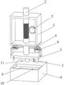
Fig. 1 is a schematic structural diagram of the present invention.
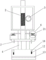
Fig. 2 is a schematic view of the front structure of the present invention.
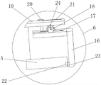
Fig. 3 is a schematic view of the clamping structure of the present invention.
Fig. 4 is a schematic top view of the cooling mechanism of the present invention.
In the figure: 1. a chassis; 2. a threaded rod; 3. a gear; 4. a connecting rod; 5. mounting a template; 6. a clamping mechanism; 7. a spring block; 8. a lower template; 9. a lower die cavity; 10. a spring hole; 11. an injection molding port; 12. a spring; 13. a cooling mechanism; 14. a water inlet joint; 15. a condenser tube; 16. a clamping plate; 17. a gear groove; 18. a second gear; 19. a connecting plate; 20. a travel bar; 21. a chute; 22. a clamping hole; 23. a clamping block; 24. and (4) connecting the blocks.
Detailed Description
The technical solutions in the embodiments of the present invention will be described clearly and completely with reference to the accompanying drawings in the embodiments of the present invention, and it is obvious that the described embodiments are only some embodiments of the present invention, not all embodiments. Based on the embodiments in the present invention, all other embodiments obtained by a person skilled in the art without creative work belong to the protection scope of the present invention.
Example 1
Referring to fig. 1-4, the present invention provides a technical solution: the utility model provides a forming device is used in production of railhead planer tool, including quick-witted case 1, the inside of quick-witted case 1 is provided with threaded rod 2, the back wall fixed mounting of quick-witted case 1 has the motor, the output of motor is installed and is geared 3 with threaded rod 2 mutually, the rear side fixedly connected with connecting rod 4 of quick-witted case 1, the bottom of threaded rod 2 is provided with cope match-plate pattern 5, the front side fixed mounting of cope match-plate pattern 5 has bullet piece 7, the right-hand member of cope match-plate pattern 5 is provided with fixture 6, the lower extreme fixedly connected with lower bolster 8 of connecting rod 4, the upper end corner position of lower bolster 8 is provided with mouth 11 of moulding plastics, lower die cavity 9 has been seted up to the upper end of lower bolster 8, the inside of lower bolster 8 is provided with cooling body 13.
Referring to fig. 2-3, the clamping mechanism 6 includes a connecting plate 19, a chute 21 is formed inside the connecting plate 19, an inner wall of the chute 21 is movably connected with a moving rod 20, a clamping plate 16 is fixedly connected to a lower end of the moving rod 20, a gear groove 17 is formed inside an upper end of the clamping plate 16, a second gear 18 is fixedly mounted at an upper end edge position of the clamping plate 16 through an output end of a motor, a clamping block 23 is fixedly connected to a right side of a lower end of the clamping plate 16, a clamping hole 22 is formed in an inner wall of a right side of the upper die plate 5, the two groups of clamping mechanisms 6 are symmetrically arranged about the threaded rod 2, the upper die plate 5 is movably connected to the bottom of the threaded rod 2 through the two groups of clamping mechanisms 6, and the motor is fixedly connected with the connecting plate 19 through a connecting block 24;
concretely, drive two 18 rotations in gear groove 17 through starter motor, two 18 gears drive grip block 16 through gear groove 17 and move right, make the left grip block of grip block 16 extract in the centre gripping hole 22 that sets up from the cope match-plate pattern right side, thereby be convenient for change the cope match-plate pattern that wears out after long-term the use, it is unqualified to reduce because of the cope match-plate pattern damages and lead to the product, influence production, wherein, grip block 16 moves at the in-process that moves right, carriage release lever 20 can move along the spout 21 that runs through on connecting plate 19 and offer, thereby spacing grip block 16, make its removal more steady.
Example 2
Referring to fig. 1-4, the present invention provides a technical solution: the utility model provides a forming device is used in production of railhead planer tool, still includes that cooling body 13 includes condenser pipe 15, and condenser pipe 15 is S type and distributes in lower bolster 8, and its one end is provided with water supply connector 14. The chassis 1 is fixedly connected with the lower template 8 through two ends of two groups of connecting plates 19, the edge position of the upper end of the lower template 8 is provided with an elastic hole 10, the bottom of the elastic hole 10 is provided with a spring 12, and the elastic block 7 is matched with the elastic hole 10;
in the forming process, through the external water pipe of water supply connector 14, can pour into water into condenser pipe 15 in, wherein condenser pipe 15 is S type and distributes in lower bolster 8, very big expansion its with lower bolster 8 area of contact, and then improve condenser pipe 15 and to lower bolster 8 cooling effect, the shaping of mould with higher speed improves the production efficiency of mould.
The working principle is as follows: firstly, the gear 3 is driven to rotate through the output end of the motor, the gear 3 drives the threaded rod 2, the threaded rod 2 moves downwards, and the threaded rod 2 can work to ascend and descend through the matching of the output end of the motor and the gear 3; the gear II 18 is driven to rotate in the gear groove 17 by the starting motor, the gear II 18 drives the clamping plate 16 to move rightwards through the gear groove 17, so that the clamping block 23 on the left side of the clamping plate 16 is pulled out from the clamping hole 22 formed in the right side of the upper template 5, the worn upper template 5 after long-term use is convenient to replace, the problem that products are unqualified and production is influenced due to the fact that the upper template 5 is damaged is solved, wherein in the process that the clamping plate 16 moves rightwards, the moving rod 20 can move along the sliding groove 21 formed in the connecting plate 19 in a penetrating mode, the clamping plate 22 is limited and moves more stably, under the clamping of the clamping mechanism 6, the threaded rod 2 enables the upper template 5 to move downwards, when the upper template 5 reaches the lower template 8, the elastic block 7 fixedly connected to the front side of the upper template 5 enters the elastic hole 10 in the upper end of the lower template 8, mold closing is completed, and then mold stripping is needed, the spring 12 rebounds in the spring hole 10 to accelerate demoulding; at last, in the forming process, through the external water pipe of water supply connector 14, can pour into water into condenser pipe 15 in, wherein condenser pipe 15 is S type and distributes in the lower bolster, very big expansion its with lower bolster 8 area of contact, and then improve condenser pipe 15 and to the cooling effect of lower bolster 8, the shaping of mould with higher speed improves the production efficiency of mould.
Although embodiments of the present invention have been shown and described, it will be appreciated by those skilled in the art that changes, modifications, substitutions and alterations can be made in these embodiments without departing from the principles and spirit of the invention, the scope of which is defined in the appended claims and their equivalents.
Claims (6)
1. The utility model provides a forming device is used in production of railhead planer tool, includes quick-witted case (1), its characterized in that: the utility model discloses a quick-witted case, including quick-witted case (1), rear wall fixed mounting of machine case (1) has the motor, and the output of motor is installed with threaded rod (2) engaged with gear (3), the rear side fixedly connected with connecting rod (4) of machine case (1), the bottom of threaded rod (2) is provided with cope match-plate pattern (5), the front side fixed mounting of cope match-plate pattern (5) has bullet piece (7), the right-hand member of cope match-plate pattern (5) is provided with fixture (6), the lower extreme fixedly connected with lower bolster (8) of connecting rod (4), the upper end corner position of lower bolster (8) is provided with mouth (11) of moulding plastics, lower die cavity (9) have been seted up to the upper end of lower bolster (8), the inside of lower bolster (8) is provided with cooling body (13).
2. The forming device for rail head planing tool production according to claim 1, wherein: fixture (6) are including connecting plate (19), spout (21) have been seted up to the inside of connecting plate (19), the lower extreme fixed link of connecting plate (19) has connecting block (24), the inner wall swing joint of spout (21) has carriage release lever (20), the lower extreme fixedly connected with grip block (16) of carriage release lever (20), gear groove (17) have been seted up to the upper end inside of grip block (16), the output end fixed mounting that the upper end border position of grip block (16) passes through the motor has gear two (18), the lower extreme right side fixedly connected with grip block (23) of grip block (16), centre gripping hole (22) have been seted up to the right side inner wall of cope match-plate pattern (5).
3. The forming device for rail head planing tool production according to claim 1, wherein: the cooling mechanism (13) comprises a condensation pipe (15), the condensation pipe (15) is distributed in the lower template (8) in an S shape, and one end of the condensation pipe is provided with a water inlet joint (14).
4. The forming device for rail head planing tool production according to claim 1, wherein: two sets of fixture (6) set up about threaded rod (2) symmetry, and cope match-plate pattern (5) are through two sets of fixture (6) swing joint is in the bottom of threaded rod (2), and the motor passes through connecting block (24) and connecting plate (19) fixed connection.
5. The forming device for rail head planing tool production according to claim 1, wherein: the case (1) is fixedly connected with the lower template (8) through two ends of two groups of connecting plates (19).
6. The forming device for rail head planing tool production according to claim 1, wherein: the upper end edge position of lower bolster (8) has seted up bullet hole (10), the bottom in bullet hole (10) is provided with spring (12), bullet piece (7) are identical with bullet hole (10).
Priority Applications (1)
| Application Number | Priority Date | Filing Date | Title |
|---|---|---|---|
| CN202220625644.XU CN217370044U (en) | 2022-03-22 | 2022-03-22 | Forming device is used in production of railhead planer tool |
Applications Claiming Priority (1)
| Application Number | Priority Date | Filing Date | Title |
|---|---|---|---|
| CN202220625644.XU CN217370044U (en) | 2022-03-22 | 2022-03-22 | Forming device is used in production of railhead planer tool |
Publications (1)
| Publication Number | Publication Date |
|---|---|
| CN217370044U true CN217370044U (en) | 2022-09-06 |
Family
ID=83101275
Family Applications (1)
| Application Number | Title | Priority Date | Filing Date |
|---|---|---|---|
| CN202220625644.XU Active CN217370044U (en) | 2022-03-22 | 2022-03-22 | Forming device is used in production of railhead planer tool |
Country Status (1)
| Country | Link |
|---|---|
| CN (1) | CN217370044U (en) |
-
2022
- 2022-03-22 CN CN202220625644.XU patent/CN217370044U/en active Active
Similar Documents
| Publication | Publication Date | Title |
|---|---|---|
| CN208148388U (en) | A kind of internal screw thread rotation depanning mold | |
| CN211105275U (en) | Novel automobile injection mold with high demolding speed | |
| CN212072753U (en) | Effectual injection mold of shaping | |
| CN217370044U (en) | Forming device is used in production of railhead planer tool | |
| CN210648061U (en) | Stamping die with replaceable stamping die head | |
| CN217968130U (en) | Injection mould with auxiliary demoulding mechanism for power supply plug-in unit shell | |
| CN216373080U (en) | A stub bar automatically cropped structure for injection mold | |
| CN211763221U (en) | Injection mold convenient to waste material is discharged and is cleared up | |
| CN211031091U (en) | Injection mold capable of automatically demolding concave parts of automobile | |
| CN212498659U (en) | High-efficient combined type injection mold | |
| CN211518347U (en) | Machining die for intelligent door lock pull handle | |
| CN211279483U (en) | Injection molding device comprising servo driving mechanism | |
| CN220373794U (en) | Plastic mold with fixed mold and movable mold inverted | |
| CN220372170U (en) | Metal casting waste output mechanism | |
| CN215550597U (en) | Mould forming structure of automobile shell part | |
| CN220260208U (en) | Clamping device for metal mold production and processing | |
| CN219025726U (en) | Metal mold slant ejector rod demoulding mechanism | |
| CN220052676U (en) | Plastic injection molding equipment convenient to drawing of patterns | |
| CN213198507U (en) | Hot pressing die for silica gel production | |
| CN216182279U (en) | Simultaneous action mechanism of shutter and insert beads | |
| CN221456602U (en) | Injection mold of deoiling unhairing limit structure | |
| CN219543952U (en) | Cooling mechanism for injection mold | |
| CN216857907U (en) | High-tonnage quick stamping device | |
| CN215550596U (en) | A mould shaping structure for leaded light post | |
| CN214920656U (en) | Slotting device for machining car roof shell die |
Legal Events
| Date | Code | Title | Description |
|---|---|---|---|
| GR01 | Patent grant | ||
| GR01 | Patent grant |