CN210703699U - Flange plate positioning and clamping device - Google Patents
Flange plate positioning and clamping device Download PDFInfo
- Publication number
- CN210703699U CN210703699U CN201921459030.3U CN201921459030U CN210703699U CN 210703699 U CN210703699 U CN 210703699U CN 201921459030 U CN201921459030 U CN 201921459030U CN 210703699 U CN210703699 U CN 210703699U
- Authority
- CN
- China
- Prior art keywords
- clamping
- positioning
- ring
- workbench
- clamping block
- Prior art date
- Legal status (The legal status is an assumption and is not a legal conclusion. Google has not performed a legal analysis and makes no representation as to the accuracy of the status listed.)
- Active
Links
Images


Abstract
The utility model discloses a flange plate positioning and clamping device, which relates to the mechanical field and comprises a workbench, a positioning round platform, a bearing, a positioning ring and a clamping mechanism, wherein the positioning round platform is fixed at the geometric center of the workbench, the bearing is arranged on the outer ring of the positioning round platform, the positioning ring is arranged on the outer ring of the bearing, 3 chutes which are circumferentially arranged are arranged on the workbench at the periphery of the positioning ring, the clamping mechanism comprises a motor seat, a clamping motor, a main gear, a driven gear, a connecting rod and a clamping block, the utility model discloses a clamping mechanism which is arranged drives the driven gear to rotate by means of the clamping motor, thereby realizing the furling of the clamping block, thereby achieving the purpose of clamping the flange plate, having fast clamping speed, simple structure and easy realization, in addition, realizing the rotation of the flange plate by arranging the bearing and the positioning ring on the outer, the fast switching of the holes to be machined is realized, the holes do not need to be disassembled and then adjusted, and the machining efficiency is improved.
Description
Technical Field
The utility model belongs to the field of machinery, concretely relates to ring flange positioning and clamping device.
Background
The ring flange belongs to a common spare part in the machinery field, and all kinds of pipelines and valves of mainly used connection are provided with a plurality of flange holes that are used for construction bolt in its main structure body, and to the processing equipment in flange hole, adopt drilling equipment to accomplish more at present, before drilling, need fix a position the ring flange and press from both sides tightly, and ring flange location clamping device among the prior art often presss from both sides the clamping speed slow, treat that the switching in processing hole is comparatively inconvenient, has influenced machining efficiency.
SUMMERY OF THE UTILITY MODEL
An object of the utility model is to provide a ring flange positioning and clamping device to solve the above-mentioned defect that leads to among the prior art.
A flange plate positioning and clamping device comprises a workbench, a positioning round platform, a bearing, a positioning ring and a clamping mechanism, wherein the positioning round platform is fixed at the geometric center of the workbench, the bearing is installed on the outer ring of the positioning round platform, the positioning ring is installed on the outer ring of the bearing, and 3 sliding grooves which are arranged in the circumferential direction are formed in the workbench at the periphery of the positioning ring;
clamping mechanism includes motor cabinet, presss from both sides tight motor, master gear, driven gear, connecting rod and presss from both sides tight piece, driven gear rotates to be connected in the bottom surface of workstation and with location round platform coaxial, press from both sides tight piece have 3 and in sliding connection and 3 spouts respectively, press from both sides the bottom of tight piece articulated the one end of connecting rod, the other end of connecting rod articulate on the location axle on the driven gear, driven gear and master gear meshing, master gear is connected to the output that presss from both sides tight motor, presss from both sides tight motor and installs in the bottom surface of workstation through pressing from both sides tight motor cabinet.
Preferably, the outer ring of the positioning ring is further provided with a rubber ring.
Preferably, the cross section of the clamping block is T-shaped, the clamping block specifically comprises a clamping block and an upright post, the upright post is fixed at the bottom of the clamping block and integrally formed with the clamping block, and the working surface of the clamping block is arc-surface-shaped.
Preferably, the clamping motor is a servo motor.
Preferably, the workbench is further provided with a feeding chute, and the feeding chute is located on one side of the positioning ring and located between the two adjacent sliding chutes.
The utility model has the advantages that: through the clamping mechanism that this application set up, it is rotatory with the help of pressing from both sides tight motor drive driven gear, and then realize pressing from both sides drawing in of tight piece to reach the purpose of pressing from both sides tight ring flange, clamping speed is fast, simple structure, easily realization, in addition, through setting up a bearing and holding ring in the outer lane of location round platform, realized the rotation of ring flange, also realized treating the fast switch-over of processing hole promptly, need not to dismantle and get off to do the adjustment again, improved machining efficiency.
Drawings
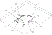
Fig. 1 and fig. 2 are schematic structural diagrams of the present invention with different viewing angles.
Fig. 3 is a schematic structural view of the middle clamping block of the present invention.
The device comprises a workbench, a positioning circular table, a bearing, a 4-positioning ring, a 5-clamping mechanism, a motor base, a motor 52-clamping motor, a main gear 53-a main gear 54-a driven gear 55-a connecting rod 56-a clamping block 561-a clamping block 562-an upright post 563-a working surface, a chute 6-a rubber ring 7-and a blanking chute 8-respectively.
Detailed Description
In order to make the technical means, creation features, achievement purposes and functions of the present invention easy to understand, the present invention is further described below with reference to the following embodiments.
As shown in fig. 1 to 3, a flange positioning and clamping device includes a workbench 1, a positioning circular truncated cone 2, a bearing 3, a positioning ring 4 and a clamping mechanism 5, wherein the positioning circular truncated cone 2 is fixed at the geometric center of the workbench 1, the bearing 3 is mounted on the outer ring of the positioning circular truncated cone 2, the positioning ring 4 is mounted on the outer ring of the bearing 3, and 3 sliding chutes 6 arranged circumferentially are arranged on the workbench 1 at the periphery of the positioning ring 4;
the clamping mechanism 5 comprises a motor base, a clamping motor 52, a main gear 53, a driven gear 54, connecting rods 55 and clamping blocks 56, wherein the driven gear 54 is rotatably connected to the bottom surface of the workbench 1 and is coaxial with the positioning circular truncated cone 2, the clamping blocks 56 are 3 and are respectively connected with the 3 sliding chutes 6 in a sliding manner, the bottom of each clamping block 56 is hinged to one end of the corresponding connecting rod 55, the other end of each connecting rod 55 is hinged to a positioning shaft on the corresponding driven gear 54, the corresponding driven gear 54 is meshed with the corresponding main gear 53, the corresponding driven gear 54 can be rotatably connected to the bottom of the workbench by means of a connecting shaft (not shown in the figure) welded to the corresponding main gear 53 and a bearing (not shown in the figure) installed at the bottom of the workbench 1, the corresponding main gear 53 is connected to the output end of the clamping motor 52, and.
In this embodiment, the outer ring of the positioning ring 4 is further provided with a rubber ring 7, and the size of the inner ring of the flange is recommended to be smaller than the outer diameter of the rubber ring 7, so that relative rotation between the installed flange and the rubber ring 7 is avoided.
In this embodiment, the cross section of the clamping block 56 is "T" shaped, and specifically includes a clamping block 561 and a vertical column 562, the vertical column 562 is fixed at the bottom of the clamping block 561 and is integrally formed therewith, a working surface of the clamping block 561 is arc-surface-shaped, and its radian is matched with the outer ring of the flange, and if necessary, a plurality of strip-shaped protrusions may be disposed on the working surface of the clamping block 561 to increase friction.
In the present embodiment, the clamping motor 52 is a servo motor.
In this embodiment, still be equipped with a charging chute 8 on workstation 1, charging chute 8 is located the one side of holding ring 4 and is in between two adjacent spouts 6, and the sweeps that the aim at drilling process of charging chute 8 produced drops from charging chute 8, simultaneously, has also reserved the drilling space for the drill bit, avoids contacting with workstation 1.
The working process and principle are as follows: in an initial state, the clamping block 56 is in an unfolded state, a worker clamps the flange plate to be processed on the outer ring of the rubber ring 7 and manually supports the flange plate according to a drilling mark punched on the flange plate, then the clamping motor 52 is started to drive the driven gear 54 to rotate, and the connecting rod 55 drives the clamping block 56 to inwardly gather to complete the rapid clamping and positioning of the flange plate. Otherwise, the flange is disassembled.
Based on the above, the utility model discloses a clamping mechanism 5 who sets up, it is rotatory with the help of tight motor 52 drive driven gear 54 of clamp, and then realize pressing from both sides drawing in of tight piece 56 to reach the purpose of pressing from both sides tight ring flange, clamping speed is fast, simple structure, easily realization, in addition, through setting up a bearing 3 and holding ring 4 in the outer lane of location round platform 2, realized the rotation of ring flange, also realized treating the fast switch-over in machined hole promptly, need not to dismantle and get off to do the adjustment again, improved machining efficiency.
It will be appreciated by those skilled in the art that the invention may be embodied in other specific forms without departing from the spirit or essential characteristics thereof. The embodiments disclosed above are therefore to be considered in all respects as illustrative and not restrictive. All changes which come within the scope of the invention or which are equivalent to the scope of the invention are embraced by the invention.
Claims (5)
1. The flange plate positioning and clamping device is characterized by comprising a workbench (1), a positioning round table (2), a bearing (3), a positioning ring (4) and a clamping mechanism (5), wherein the positioning round table (2) is fixed at the geometric center of the workbench (1), the bearing (3) is installed on the outer ring of the positioning round table (2), the positioning ring (4) is installed on the outer ring of the bearing (3), and 3 sliding chutes (6) which are circumferentially arranged are formed in the workbench (1) at the periphery of the positioning ring (4);
the clamping mechanism (5) comprises a motor base, a clamping motor (52), a main gear (53), a driven gear (54), a connecting rod (55) and a clamping block (56), wherein the driven gear (54) is rotatably connected to the bottom surface of the workbench (1) and is coaxial with the positioning circular truncated cone (2), the clamping block (56) is provided with 3 sliding blocks which are respectively connected with the 3 sliding grooves (6) in a sliding mode, the bottom of the clamping block (56) is hinged to one end of the connecting rod (55), the other end of the connecting rod (55) is hinged to a positioning shaft on the driven gear (54), the driven gear (54) is meshed with the main gear (53), the main gear (53) is connected to the output end of the clamping motor (52), and the clamping motor (52) is installed on the bottom surface of the workbench (1) through the clamping motor (52) base.
2. The flange positioning and clamping device as set forth in claim 1, wherein: the outer ring of the positioning ring (4) is also provided with a rubber ring (7).
3. The flange positioning and clamping device as set forth in claim 2, wherein: the cross section of the clamping block (56) is T-shaped, the clamping block specifically comprises a clamping block (561) and an upright post (562), the upright post (562) is fixed at the bottom of the clamping block (561) and is integrally formed with the clamping block, and the working surface of the clamping block (561) is arc-surface-shaped.
4. The flange positioning and clamping device as set forth in claim 1, wherein: the clamping motor (52) adopts a servo motor.
5. The flange positioning and clamping device as set forth in claim 1, wherein: the workbench (1) is further provided with a charging chute (8), and the charging chute (8) is located on one side of the positioning ring (4) and located between the two adjacent sliding chutes (6).
Priority Applications (1)
| Application Number | Priority Date | Filing Date | Title |
|---|---|---|---|
| CN201921459030.3U CN210703699U (en) | 2019-09-04 | 2019-09-04 | Flange plate positioning and clamping device |
Applications Claiming Priority (1)
| Application Number | Priority Date | Filing Date | Title |
|---|---|---|---|
| CN201921459030.3U CN210703699U (en) | 2019-09-04 | 2019-09-04 | Flange plate positioning and clamping device |
Publications (1)
| Publication Number | Publication Date |
|---|---|
| CN210703699U true CN210703699U (en) | 2020-06-09 |
Family
ID=70926038
Family Applications (1)
| Application Number | Title | Priority Date | Filing Date |
|---|---|---|---|
| CN201921459030.3U Active CN210703699U (en) | 2019-09-04 | 2019-09-04 | Flange plate positioning and clamping device |
Country Status (1)
| Country | Link |
|---|---|
| CN (1) | CN210703699U (en) |
Cited By (1)
| Publication number | Priority date | Publication date | Assignee | Title |
|---|---|---|---|---|
| CN112093452A (en) * | 2020-11-23 | 2020-12-18 | 北京中航科电测控技术股份有限公司 | Spare and accessory part manufacturing process and automatic intelligent manufacturing equipment |
-
2019
- 2019-09-04 CN CN201921459030.3U patent/CN210703699U/en active Active
Cited By (1)
| Publication number | Priority date | Publication date | Assignee | Title |
|---|---|---|---|---|
| CN112093452A (en) * | 2020-11-23 | 2020-12-18 | 北京中航科电测控技术股份有限公司 | Spare and accessory part manufacturing process and automatic intelligent manufacturing equipment |
Similar Documents
| Publication | Publication Date | Title |
|---|---|---|
| CN210756500U (en) | Flange plate drilling equipment | |
| CN107999815B (en) | A kind of working method of flange automatic drilling equipment | |
| CN203875677U (en) | Feeding and discharging manipulator | |
| CN101885130B (en) | Automatic circular seam welding pipe tongs | |
| CN103963102B (en) | A kind of full-automatic multistation tubing tridimensional stamping equipment | |
| CN103801959A (en) | Self-centering clamping device of drill press workpiece | |
| CN103817553A (en) | Workpiece automatic clamping device | |
| CN202556085U (en) | Automatic centring clamp | |
| CN101774132A (en) | Reducer shell-drilling-and-tapping turnover jig | |
| CN106670663A (en) | Chuck device | |
| CN210703699U (en) | Flange plate positioning and clamping device | |
| CN210632873U (en) | Forging device for freely forging large-diameter ring type hole expanding | |
| CN109622699B (en) | Pipeline groove cutting machine | |
| CN209078157U (en) | A kind of structure is improved to hold round tooling | |
| CN102085617B (en) | Novel numerical control machine vertical rotating table | |
| CN212705598U (en) | Excavator planet carrier is with fixed frock | |
| CN110497040B (en) | Mechanical expansion type gear shaving clamp for machining large gear ring | |
| CN112170942B (en) | A prop tight positioning mechanism for abandonment stake pipe cutting | |
| CN212265081U (en) | Automobile transmission shaft universal joint assembly press-fitting tool | |
| CN205201057U (en) | Cylinder body processing fixing device | |
| CN211162689U (en) | Large taper pipe welding positioner | |
| CN208713767U (en) | A kind of fixture processed for fixing motor housing | |
| CN214517959U (en) | Device for cutting bevel of elbow | |
| CN206689921U (en) | A kind of Workpiece clamping slewing equipment for multiaspect polishing machine | |
| CN215658766U (en) | Pipe to pipe welding set |
Legal Events
| Date | Code | Title | Description |
|---|---|---|---|
| GR01 | Patent grant | ||
| GR01 | Patent grant |