CN210632873U - Forging device for freely forging large-diameter ring type hole expanding - Google Patents
Forging device for freely forging large-diameter ring type hole expanding Download PDFInfo
- Publication number
- CN210632873U CN210632873U CN201921730987.7U CN201921730987U CN210632873U CN 210632873 U CN210632873 U CN 210632873U CN 201921730987 U CN201921730987 U CN 201921730987U CN 210632873 U CN210632873 U CN 210632873U
- Authority
- CN
- China
- Prior art keywords
- forging
- transmission case
- sliding block
- gear
- motor
- Prior art date
- Legal status (The legal status is an assumption and is not a legal conclusion. Google has not performed a legal analysis and makes no representation as to the accuracy of the status listed.)
- Expired - Fee Related
Links
- 238000005242 forging Methods 0.000 title claims abstract description 93
- 230000005540 biological transmission Effects 0.000 claims abstract description 43
- 239000000463 material Substances 0.000 claims abstract description 37
- 238000009434 installation Methods 0.000 claims abstract description 11
- 239000000956 alloy Substances 0.000 claims description 2
- 238000006049 ring expansion reaction Methods 0.000 claims 6
- 230000008878 coupling Effects 0.000 abstract description 4
- 238000010168 coupling process Methods 0.000 abstract description 4
- 238000005859 coupling reaction Methods 0.000 abstract description 4
- 238000007373 indentation Methods 0.000 abstract description 3
- 238000003825 pressing Methods 0.000 abstract description 3
- 238000010438 heat treatment Methods 0.000 description 4
- 238000004519 manufacturing process Methods 0.000 description 4
- 238000000034 method Methods 0.000 description 4
- 230000002349 favourable effect Effects 0.000 description 3
- 230000004048 modification Effects 0.000 description 2
- 238000012986 modification Methods 0.000 description 2
- 230000008569 process Effects 0.000 description 2
- 208000034656 Contusions Diseases 0.000 description 1
- 230000009286 beneficial effect Effects 0.000 description 1
- 208000034526 bruise Diseases 0.000 description 1
- 244000309464 bull Species 0.000 description 1
- 230000007547 defect Effects 0.000 description 1
- 230000000694 effects Effects 0.000 description 1
- 230000006872 improvement Effects 0.000 description 1
- 238000009776 industrial production Methods 0.000 description 1
- 239000002184 metal Substances 0.000 description 1
- 230000007306 turnover Effects 0.000 description 1
- 238000003466 welding Methods 0.000 description 1
Images


Classifications
-
- Y—GENERAL TAGGING OF NEW TECHNOLOGICAL DEVELOPMENTS; GENERAL TAGGING OF CROSS-SECTIONAL TECHNOLOGIES SPANNING OVER SEVERAL SECTIONS OF THE IPC; TECHNICAL SUBJECTS COVERED BY FORMER USPC CROSS-REFERENCE ART COLLECTIONS [XRACs] AND DIGESTS
- Y02—TECHNOLOGIES OR APPLICATIONS FOR MITIGATION OR ADAPTATION AGAINST CLIMATE CHANGE
- Y02P—CLIMATE CHANGE MITIGATION TECHNOLOGIES IN THE PRODUCTION OR PROCESSING OF GOODS
- Y02P70/00—Climate change mitigation technologies in the production process for final industrial or consumer products
- Y02P70/10—Greenhouse gas [GHG] capture, material saving, heat recovery or other energy efficient measures, e.g. motor control, characterised by manufacturing processes, e.g. for rolling metal or metal working
Landscapes
- Forging (AREA)
Abstract
The utility model belongs to the technical field of freely forge major diameter lopps reaming, especially, be a freely forge forging device for major diameter lopps reaming, including base, transmission case one and transmission case two, inverter motor is installed to upper end one side of base, is provided with the shaft coupling between inverter motor and the transmission case one, and four corner fixed mounting in transmission case one upper end have the support column, and the one end that transmission case one was kept away from to the support column is provided with the workstation, and transversely has seted up the installation cavity on the workstation, and the inside of installation cavity is provided with the lead screw, installs threaded connection's first slider and second slider on the lead screw. The utility model discloses, replace artifical operation mode who rotates the installation work piece with forging the material carousel to utilize inverter motor to be the power supply, reduced operator's intensity of labour, practiced thrift the human cost, improved work efficiency, reduce and forge the material and press from both sides the phenomenon that the indentation appears in the surface when pressing from both sides tightly fixed processing, the slip of application lead screw and slider, the drive ratio is big, easily control.
Description
Technical Field
The utility model relates to a free forging major diameter lopps reaming technical field specifically is a free forging major diameter lopps forging device for reaming.
Background
With the rapid development of the mechanical field in China, the requirements on the mechanical properties such as strength and the like of parts are higher and higher, and forging becomes increasingly important in industrial production, wherein free forging is widely applied to the manufacturing field as an important forging mode. Free forging is a method of processing a forging piece, called free forging for short, in which metal is freely deformed in all directions between upper and lower anvil surfaces by impact force or pressure, and a desired shape, size and certain mechanical properties are obtained without any restriction. The free forging has the advantages of simple tools and equipment, good universality and low cost. Compared with a cast blank, the free forging eliminates the defects of shrinkage cavity, shrinkage porosity, air holes and the like, so that the blank has higher mechanical property, and the forged piece has simple shape and flexible operation. Therefore, it is of particular importance in the manufacture of heavy machines and of important parts. The existing free forging device has the following problems:
1. the existing free forging equipment generally uses a clamp type operating machine to clamp a forging to turn over and move, the forging is inconvenient to move and rotate, the clamp type operating machine clamps a workpiece on a common workbench, the workpiece is placed on the common workbench after being turned over or moved and then loosened, so that the labor intensity of workers is very high, the production efficiency is low, the rotation amplitude of the forging is mastered by the experience of the workers, and the condition that the wall thickness of the forged forging is uneven is easy to occur;
2. the workpiece of the existing free forging equipment needs at least 2 minutes when changing the position once, and a person who starts the operating machine needs to be close to the high-temperature workpiece in the 2 minutes and also needs to be careful in operation, otherwise the workpiece falls to the ground and damages the workpiece because of not being tightened or turned over, the workpiece is scrapped or needs to enter a heating furnace again for heating, and certain potential safety hazards exist.
SUMMERY OF THE UTILITY MODEL
Technical problem to be solved
The utility model provides a not enough to prior art, the utility model provides a free forging major diameter lopps forging device for reaming, it generally uses clamp type operation machine to clamp the forging and overturns and remove to have solved current free forging equipment, the forging removes with rotate inconveniently, production efficiency is lower, the inhomogeneous condition of forging wall thickness and work piece after taking place easily to forge will fall ground and bruise the work piece because of not step up or overturn, lead to the work piece to scrap or need get into the heating furnace heating once more, there is certain potential safety hazard problem.
(II) technical scheme
In order to achieve the above object, the utility model provides a following technical scheme:
a forging device for freely forging large-diameter ring-shaped counterbores comprises a base, a first transmission case and a second transmission case, a variable frequency motor is arranged on one side of the upper end of the base, a coupling is arranged between the variable frequency motor and the first transmission case, supporting columns are fixedly arranged at four corners of the upper end of the first transmission box, a workbench is arranged at one end of each supporting column far away from the first transmission box, and the worktable is transversely provided with an installation cavity, the installation cavity is internally provided with a screw rod, the screw rod is provided with a first slide block and a second slide block which are connected by screw thread, the upper surfaces of the first sliding block and the second sliding block are both fixedly provided with connecting rods, one end of each connecting rod far away from the first sliding block is fixedly provided with a chuck, the material carousel is forged to the upper surface central point of workstation puts and is provided with, the lower extreme of forging the material carousel rotates and is connected with the rotation axis, the rotation axis runs through the workstation and extends to in the transmission case two.
As an optimal technical scheme of the utility model, the both ends of lead screw are all rotated through the inside wall of bearing and installation cavity and are connected, first slider and second slider distribute respectively in the both sides of lead screw.
As an optimized technical scheme of the utility model, the shape of chuck exposed core is convex, and the centre gripping direction of two chucks sets up in opposite directions.
As an optimal technical scheme of the utility model, two package motors, first belt pulley, conveyer belt, transmission shaft, second belt pulley and motor fixing base of transmission case are constituteed, the motor passes through bolt fixed mounting at the upper surface of motor fixing base, and the motor rotates through the transmission shaft and is connected with the second belt pulley, the second belt pulley passes through the conveyer belt and is connected with first belt pulley rotation, and first belt pulley rotates and connects the central point at the lead screw and put.
As a preferred technical scheme of the utility model, transmission case one includes bevel pinion, big bevel gear, pinion, gear wheel and rotation axis, bevel pinion's input passes through the bearing and is connected with the shaft coupling rotation, bevel pinion and big bevel gear meshing are connected, and the pinion is connected with big bevel gear meshing, the rotation axis passes through the bearing and is connected with the centre bore rotation of gear wheel.
As an optimal technical scheme of the utility model, first slider and second slider are respectively through screw hole and lead screw threaded connection, the material of forging the material carousel is the carbide material.
As an optimized technical scheme of the utility model, the quantity of support column is four groups, and the upper surface of four group's support columns and the lower extreme surface welded fastening of workstation.
(III) advantageous effects
Compared with the prior art, the utility model provides a freely forge forging device for reaming of major diameter lopps possesses following beneficial effect:
1. according to the forging device for freely forging the large-diameter ring for reaming, the forging material rotary table is used for replacing an operation mode of manually rotating and mounting the workpiece, the variable frequency motor is used as a power source, the rotating speed of the forging material rotary table can be flexibly set according to the size of the workpiece, variable speed rotation is realized, the rotating angular speed selection range is large, the labor intensity of an operator is reduced, the labor cost is saved, and the working efficiency is improved;
2. this forging device is used in reaming of free forging major diameter lopps, the exposed core of two chucks is the arc, reduces to forge the material and processes the phenomenon that the indentation appears in the surface when pressing from both sides tightly fixed, utilizes the slip of lead screw and slider, and the drive ratio is big, and easily control is better to be favorable to the chuck and forges the cooperation of material.
Drawings
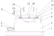
FIG. 1 is a schematic view of the overall structure of a forging apparatus for freely forging large-diameter ring-type hole enlargement according to the present invention;
FIG. 2 is a schematic view of the internal structure of a transmission case II of the forging apparatus for freely forging large-diameter ring-type hole enlargement of the present invention;
fig. 3 is a schematic view of an internal structure of a transmission case of a forging apparatus for free forging of large-diameter ring.
FIG. 1, base; 2. a first transmission case; 201. a bevel pinion gear; 202. a large bevel gear; 203. a pinion gear; 204. a bull gear; 3. a second transmission case; 4. a variable frequency motor; 5. a coupling; 6. a support pillar; 7. a work table; 8. a rotating shaft; 9. a mounting cavity; 10. a first slider; 11. a screw rod; 12. a second slider; 13. a connecting rod; 14. a chuck; 15. a forging material turntable; 16. a first pulley; 17. a conveyor belt; 18. a second pulley; 19. a drive shaft; 20. a motor fixing seat; 21. an electric motor.
Detailed Description
The technical solutions in the embodiments of the present invention will be described clearly and completely with reference to the accompanying drawings in the embodiments of the present invention, and it is obvious that the described embodiments are only some embodiments of the present invention, not all embodiments. Based on the embodiments in the present invention, all other embodiments obtained by a person skilled in the art without creative work belong to the protection scope of the present invention.
Referring to fig. 1-3, the present invention provides the following technical solutions: a forging device for reaming a freely forged large-diameter ring comprises a base 1, a first transmission case 2 and a second transmission case 3, wherein a variable frequency motor 4 is installed on one side of the upper end of the base 1, a coupler 5 is arranged between the variable frequency motor 4 and the first transmission case 2, supporting columns 6 are fixedly installed at four corners of the upper end of the first transmission case 2, a workbench 7 is arranged at one end, far away from the first transmission case 2, of each supporting column 6, an installation cavity 9 is transversely formed in each workbench 7, a lead screw 11 is arranged inside each installation cavity 9, a first sliding block 10 and a second sliding block 12 which are in threaded connection are installed on each lead screw 11, connecting rods 13 are fixedly installed on the upper surfaces of the first sliding block 10 and the second sliding block 12, a chuck 14 is fixedly installed at one end, far away from the first sliding block 10, of each connecting rod 13, a forging material rotating disc 15 is arranged at the central position of, the rotating shaft 8 penetrates through the workbench 7 and extends into the second transmission case 3.
In the embodiment, the type of the arranged variable frequency motor 4 is YVF-160L-4, the variable frequency motor 4 is used as a power source, the rotating speed of the forging material turntable 15 can be flexibly set according to the size of a workpiece, variable speed rotation is realized, the rotating angular speed selection range is wide, and the application range of the forging material turntable 15 is wide; the first sliding block 10 and the second sliding block 12 slide oppositely on the screw rod 11 under the driving of the second transmission case 3, so that the clamping head 14 can fix the forging material conveniently, the labor intensity is reduced, and the working efficiency is improved; the stability of workstation 7 has been improved to the support column 6 that sets up.
Specifically, both ends of the screw rod 11 are rotatably connected with the inner side wall of the mounting cavity 9 through bearings, and the first sliding block 10 and the second sliding block 12 are respectively distributed on both sides of the screw rod 11.
In this embodiment, the motor 21 drives the screw rod 11, so that the first slider 10 and the second slider 12 slide in opposite directions until the two chucks 14 fix the two side walls of the forging material, thereby reducing labor intensity and improving working efficiency, wherein the model of the motor 21 is Y80M 1-2.
Specifically, the shape of the clamping end of the clamping head 14 is circular arc, and the clamping directions of the two clamping heads 14 are opposite.
In this embodiment, it is favorable to letting chuck 14 fix the forging material, easily control, and better be favorable to the cooperation of chuck 14 and forging material, and reduce the phenomenon that the surface indentation appears when the forging material is processed to press from both sides tightly fixed.
Specifically, transmission case two 3 includes that motor 21, first belt pulley 16, conveyer belt 17, transmission shaft 19, second belt pulley 18 and motor fixing base 20 constitute, and motor 21 passes through bolt fixed mounting at the upper surface of motor fixing base 20, and motor 21 rotates through transmission shaft 19 and is connected with second belt pulley 18, and second belt pulley 18 rotates through conveyer belt 17 and first belt pulley 16 to be connected, and first belt pulley 16 rotates to be connected at the central point of lead screw 11 and puts.
In this embodiment, the motor 21 drives the second belt pulley 18 to rotate, so that the transmission belt 17 transmits power to the screw rod 11 to drive the screw rod to rotate, and the first slider 10 and the second slider 12 slide in opposite directions until the two chucks 14 fix the two side walls of the forging material, thereby reducing labor intensity and improving work efficiency.
Specifically, the first transmission case 2 comprises a small bevel gear 201, a large bevel gear 202, a small gear 203, a large gear 204 and a rotating shaft 8, wherein the input end of the small bevel gear 201 is rotatably connected with the coupler 5 through a bearing, the small bevel gear 201 is meshed with the large bevel gear 202, the small gear 203 is meshed with the large gear 204, and the rotating shaft 8 is rotatably connected with a central hole of the large gear 204 through a bearing.
In this embodiment, transmission case 2 through setting up, under inverter motor 4's rotation, drive the rotation of bevel pinion 201, thereby drive bevel pinion 202's rotation, pinion 203 follows the rotation together with the gear wheel 204 of meshing under the drive of pivot, the rotation through gear wheel 204 at last further drives the rotation of the material carousel 15 of forging that connects on the rotation axis 8, replace the artifical operation mode who rotates the installation work piece with material carousel 15 of forging, operator's intensity of labour has been reduced, the human cost is practiced thrift, and the work efficiency is improved.
Specifically, the first slide block 10 and the second slide block 12 are respectively in threaded connection with the screw rod 11 through threaded holes, and the material of the forging material rotating disc 15 is hard alloy material.
In this embodiment, since the thread directions of the first slider 10 and the second slider 12 are opposite, the first slider 10 and the second slider 12 slide towards each other until the two collets 14 clamp and fix the two side walls of the forging material, so as to increase the flexibility of the forging device.
Specifically, the number of the support columns 6 is four, and the upper surfaces of the four support columns 6 are welded and fixed with the outer surface of the lower end of the workbench 7.
In this embodiment, the bottom surface area of the support column 6 is large, and the support column is connected with the forging device into a whole through welding fixation, so that the stability of the workbench 7 is improved.
The utility model discloses a theory of operation and use flow: when the forging press hammer is used, the starting motor 21 drives the second belt pulley 18 to rotate under the control of the remote control console, so that power is transmitted to the screw rod 11 through the transmission belt 17 to drive the screw rod to rotate, the first sliding block 10 and the second sliding block 12 slide oppositely until the two clamping heads 14 fix two side walls of a forging material, the variable frequency motor 4 has a starting condition when the forging press hammer moves upwards to an upper limit position, and the variable frequency motor 4 cannot be started when the forging press hammer moves upwards to any position between the forging material rotating disc 15 and the upper limit position; when the variable frequency motor 4 is in the operation process, at the moment, the rotation of the small bevel gear 201 is driven under the rotation of the variable frequency motor 4, so that the rotation of the large bevel gear 202 is driven, the small gear 203 is driven by the rotating shaft to rotate the meshed large gear 204 together, finally, the rotation of the forging material rotating disc 15 connected to the rotating shaft 8 is further driven through the rotation of the large gear 204, the operation mode of installing a workpiece is replaced by the manual rotation of the forging material rotating disc 15, after the forging material angle is adjusted, the motor 21 is started again to clamp the forging material, the variable frequency motor 4 and the motor 21 are closed, the forging material is forged for the first time, the operation is repeated in such a way until all processing procedures including hole expanding, forging and pressing are completed, the labor intensity of operators is reduced, the labor cost is saved, and the working efficiency is improved.
Finally, it should be noted that: although the present invention has been described in detail with reference to the foregoing embodiments, it will be apparent to those skilled in the art that modifications may be made to the embodiments described in the foregoing embodiments, or equivalents may be substituted for elements thereof. Any modification, equivalent replacement, or improvement made within the spirit and principle of the present invention should be included in the protection scope of the present invention.
Claims (7)
1. The utility model provides a forging device is used in free forging major diameter lopps reaming, includes base (1), transmission case one (2) and transmission case two (3), its characterized in that: the automatic forging machine is characterized in that a variable frequency motor (4) is installed on one side of the upper end of the base (1), a coupler (5) is arranged between the variable frequency motor (4) and the transmission case I (2), supporting columns (6) are fixedly installed on four corners of the upper end of the transmission case I (2), a workbench (7) is arranged at one end, away from the transmission case I (2), of each supporting column (6), an installation cavity (9) is transversely formed in the workbench (7), a lead screw (11) is arranged inside the installation cavity (9), a first sliding block (10) and a second sliding block (12) which are in threaded connection are installed on the lead screw (11), connecting rods (13) are fixedly installed on the upper surfaces of the first sliding block (10) and the second sliding block (12), a chuck (14) is fixedly installed at one end, away from the first sliding block (10), of each connecting rod (13), and a forging material rotating disc (15) is arranged at the center, the lower end of the forging material turntable (15) is rotatably connected with a rotating shaft (8), and the rotating shaft (8) penetrates through the workbench (7) and extends into the second transmission case (3).
2. The forging apparatus for free forging large-diameter ring expansion as recited in claim 1, wherein: the two ends of the screw rod (11) are rotatably connected with the inner side wall of the mounting cavity (9) through bearings, and the first sliding block (10) and the second sliding block (12) are respectively distributed on two sides of the screw rod (11).
3. The forging apparatus for free forging large-diameter ring expansion as recited in claim 1, wherein: the clamping ends of the clamping heads (14) are arc-shaped, and the clamping directions of the two clamping heads (14) are opposite.
4. The forging apparatus for free forging large-diameter ring expansion as recited in claim 1, wherein: transmission case two (3) include motor (21), first belt pulley (16), conveyer belt (17), transmission shaft (19), second belt pulley (18) and motor fixing base (20) and constitute, bolt fixed mounting is passed through at the upper surface of motor fixing base (20) in motor (21), and motor (21) rotate through transmission shaft (19) and be connected with second belt pulley (18), second belt pulley (18) rotate with first belt pulley (16) through conveyer belt (17) and are connected, and first belt pulley (16) rotate the central point that connects at lead screw (11) and put.
5. The forging apparatus for free forging large-diameter ring expansion as recited in claim 1, wherein: the first transmission case (2) comprises a small bevel gear (201), a large bevel gear (202), a small gear (203), a large gear (204) and a rotating shaft (8), the input end of the small bevel gear (201) is rotatably connected with a coupler (5) through a bearing, the small bevel gear (201) is meshed with the large bevel gear (202) and the small gear (203) is meshed with the large gear (204) and is connected with the large gear, and the rotating shaft (8) is rotatably connected with a center hole of the large gear (204) through the bearing.
6. The forging apparatus for free forging large-diameter ring expansion as recited in claim 1, wherein: the first sliding block (10) and the second sliding block (12) are in threaded connection with the screw rod (11) through threaded holes respectively, and the material of the forging material rotating disc (15) is hard alloy material.
7. The forging apparatus for free forging large-diameter ring expansion as recited in claim 1, wherein: the number of the support columns (6) is four, and the upper surfaces of the four support columns (6) are welded and fixed with the outer surface of the lower end of the workbench (7).
Priority Applications (1)
| Application Number | Priority Date | Filing Date | Title |
|---|---|---|---|
| CN201921730987.7U CN210632873U (en) | 2019-10-16 | 2019-10-16 | Forging device for freely forging large-diameter ring type hole expanding |
Applications Claiming Priority (1)
| Application Number | Priority Date | Filing Date | Title |
|---|---|---|---|
| CN201921730987.7U CN210632873U (en) | 2019-10-16 | 2019-10-16 | Forging device for freely forging large-diameter ring type hole expanding |
Publications (1)
| Publication Number | Publication Date |
|---|---|
| CN210632873U true CN210632873U (en) | 2020-05-29 |
Family
ID=70793990
Family Applications (1)
| Application Number | Title | Priority Date | Filing Date |
|---|---|---|---|
| CN201921730987.7U Expired - Fee Related CN210632873U (en) | 2019-10-16 | 2019-10-16 | Forging device for freely forging large-diameter ring type hole expanding |
Country Status (1)
| Country | Link |
|---|---|
| CN (1) | CN210632873U (en) |
Cited By (3)
| Publication number | Priority date | Publication date | Assignee | Title |
|---|---|---|---|---|
| CN111633169A (en) * | 2020-06-04 | 2020-09-08 | 马鞍山市福德机械制造有限公司 | Forging process for die pressing groove of groove ring |
| CN112475190A (en) * | 2020-09-29 | 2021-03-12 | 冯建华 | Energy-concerving and environment-protective portable horseshoe forges clamping device |
| CN112475171A (en) * | 2020-11-09 | 2021-03-12 | 谢娟 | Novel automatic forging forming device |
-
2019
- 2019-10-16 CN CN201921730987.7U patent/CN210632873U/en not_active Expired - Fee Related
Cited By (3)
| Publication number | Priority date | Publication date | Assignee | Title |
|---|---|---|---|---|
| CN111633169A (en) * | 2020-06-04 | 2020-09-08 | 马鞍山市福德机械制造有限公司 | Forging process for die pressing groove of groove ring |
| CN112475190A (en) * | 2020-09-29 | 2021-03-12 | 冯建华 | Energy-concerving and environment-protective portable horseshoe forges clamping device |
| CN112475171A (en) * | 2020-11-09 | 2021-03-12 | 谢娟 | Novel automatic forging forming device |
Similar Documents
| Publication | Publication Date | Title |
|---|---|---|
| CN210632873U (en) | Forging device for freely forging large-diameter ring type hole expanding | |
| CN210938264U (en) | Workpiece clamping device for numerical control milling machine | |
| CN104942508A (en) | Lifting mechanical working table | |
| CN212239744U (en) | Multi-angle rotating welding machine for electrical engineering machining | |
| CN206356811U (en) | A kind of rapid welding clamping device | |
| CN203184805U (en) | Automatic circumferential weld welding tool of electric car water-cooling engine base | |
| CN211840781U (en) | Be applied to triaxial machine of shifting of rotating member build-up welding | |
| CN112935952A (en) | Rigid cylindrical grinding method and device for miniature round rod | |
| CN116765726A (en) | Automatic welding device and method thereof | |
| CN215091607U (en) | Flange concatenation formula welding frock | |
| CN213438073U (en) | Multi-station welding device for mechanical workpieces | |
| CN208033981U (en) | A kind of jack welding machine special | |
| CN212420048U (en) | Semi-automatic plasma cutting annular groove processing device | |
| CN211465604U (en) | Plate pneumatic clamp for numerical control machining center | |
| CN211680732U (en) | Clamping device with variable positions | |
| CN210359595U (en) | Double-shaft chamfering machine head | |
| CN211588634U (en) | Tool of drill jig for drilling circumferential surface of water pump motor end cover | |
| CN218926121U (en) | Forging device for engineering machinery accessory machining | |
| CN219752367U (en) | Automatic turntable of high-frequency quenching machine tool | |
| CN216680687U (en) | Friction welding positioning tool for special-shaped rod of automobile shock absorber | |
| CN114453601B (en) | Adjustable curved wheel machining cutter | |
| CN211439368U (en) | Metal product lower rack positioning tool | |
| CN217965249U (en) | Seam welder is used in cement manufacture | |
| CN219542200U (en) | Pull ring welding machine | |
| CN213381570U (en) | Blank taking manipulator |
Legal Events
| Date | Code | Title | Description |
|---|---|---|---|
| GR01 | Patent grant | ||
| GR01 | Patent grant | ||
| PE01 | Entry into force of the registration of the contract for pledge of patent right | ||
| PE01 | Entry into force of the registration of the contract for pledge of patent right |
Denomination of utility model: A forging device for free forging large diameter ring reaming Effective date of registration: 20210402 Granted publication date: 20200529 Pledgee: Bank of China Limited Wenshang sub branch Pledgor: Jining Yonghao Machinery Co.,Ltd. Registration number: Y2021980002399 |
|
| CF01 | Termination of patent right due to non-payment of annual fee | ||
| CF01 | Termination of patent right due to non-payment of annual fee |
Granted publication date: 20200529 |