CN210695914U - Pasture scattering equipment - Google Patents
Pasture scattering equipment Download PDFInfo
- Publication number
- CN210695914U CN210695914U CN201921741511.3U CN201921741511U CN210695914U CN 210695914 U CN210695914 U CN 210695914U CN 201921741511 U CN201921741511 U CN 201921741511U CN 210695914 U CN210695914 U CN 210695914U
- Authority
- CN
- China
- Prior art keywords
- close
- fixedly connected
- rotating shaft
- crushing
- box
- Prior art date
- Legal status (The legal status is an assumption and is not a legal conclusion. Google has not performed a legal analysis and makes no representation as to the accuracy of the status listed.)
- Expired - Fee Related
Links
Images


Abstract
The utility model discloses a grass equipment of breaing up, including smashing the case, smash the left side fixedly connected with backup pad that is close to its top on the case, the upper surface of backup pad has driving machine one through link fixed mounting, the first crushing sword of telescopic circumference inner wall fixedly connected with, the gear is connected with outer ring gear meshing, smash the inner wall fixedly connected with division board that is close to its middle part on the case, carry and expect that the mechanism goes up to be close to its bottom and be close to one side of smashing the case and seted up the pan feeding mouth, and the pan feeding mouth link up with smashing the case each other. The utility model discloses an above-mentioned isotructure's cooperation has been solved current forage grass and has been broken up equipment, breaks up and smashes the effect relatively poor, and is difficult for stirring the mixing processing to forage grass and fodder in the kibbling in-process of forage grass with smash after accomplishing, and the function is comparatively single, is difficult for carrying out drying process to forage grass at kibbling in-process, has reduced the problem of the efficiency of forage grass processing.
Description
Technical Field
The utility model relates to a forage grass processing technology field specifically is a equipment is broken up to forage grass.
Background
Animal husbandry is one of the components of agriculture, and is listed as two major pillars of agricultural production together with the planting industry, and the animal husbandry is a production department which utilizes animals, such as livestock and poultry, which are domesticated by human beings to convert the plant energy, such as pasture, feed and the like, into animal energy through artificial feeding and breeding so as to obtain animal products, such as meat, eggs, milk, wool, cashmere, hide, silk, medicinal materials and the like. The pasture is generally the grass or other herbaceous plants used by the raised livestock, has strong regeneration capacity, can be harvested for many times a year, is rich in various trace elements and vitamins, and therefore becomes the first choice for raising livestock, contains various nutrient substances necessary for the livestock and also contains crude fibers which are particularly important for maintaining the health of the ruminant livestock, and cannot be replaced by grains and other feeds.
Because current forage grass is broken up equipment, it is relatively poor to break up crushing effect, and is difficult to stir the mixing processing to forage grass and fodder in the kibbling in-process of forage grass and crushing completion back, and the function is comparatively single, is difficult to carry out drying process to forage grass at kibbling in-process, has reduced the efficiency of forage grass processing, consequently needs to improve.
SUMMERY OF THE UTILITY MODEL
An object of the utility model is to provide a grass equipment of breaing up, it can circulate to smash to possess, and can carry out drying process to grass at kibbling in-process, the grass after smashing simultaneously can get into the division board below and stir the mixing with fodder or other forage grass, and the division board top is used for the forage grass to smash, the below then is used for the forage grass mixing, the different equipment that need be changed to the forage grass after having avoided smashing carries out mixing processing, make the forage grass smash, the mixing integration is accomplished, the advantage of forage grass processing treatment efficiency has been improved, the problem of proposing in the background art has been solved.
In order to achieve the above object, the utility model provides a following technical scheme: pasture grass scattering equipment comprises a crushing box, wherein supporting legs are arranged at the bottom of the crushing box, a supporting plate is fixedly connected to the left side of the crushing box, which is close to the top of the crushing box, a first driving machine is fixedly mounted on the upper surface of the supporting plate through a connecting frame, a first rotating shaft is fixedly connected to the output end of the first driving machine, the first rotating shaft is rotatably connected with the supporting plate through a bearing, a gear is fixedly connected to the surface of the first rotating shaft, which is close to the bottom of the first rotating shaft, a sleeve with openings at two ends is rotatably connected to the inner wall of the crushing box, which is close to the top of the crushing box, a first crushing blade is fixedly connected to the circumferential inner wall of the sleeve, an outer gear ring is fixedly connected to the surface of the sleeve, which is close to the middle of the sleeve, the gear is meshed with, and be close to the surperficial fixedly connected with stirring piece of its bottom in the pivot two, smash the right side that is close to its bottom on the case and seted up the material and add the mouth, the equal fixedly connected with belt pulley in surface that is close to its top in pivot one and the pivot two, and connect through belt transmission between two belt pulleys, the surperficial fixedly connected with crushing piece that is close to its top in the pivot two, and crushing piece is located the sleeve, be close to the rear side fixedly connected with lifting mechanism at its middle part on crushing case, the last bin outlet of having seted up near one side of its top and being close to crushing case that is close to of lifting mechanism, the last pan feeding mouth of having seted up near one side of its bottom and being close to crushing case that is close to of lifting mechanism, and pan feeding mouth.
Preferably, the stirring piece includes three puddler, three puddler fixed connection is on the surface of being close to its bottom on the pivot two, and three puddler from the top down length reduces in proper order.
Preferably, the crushing piece comprises an eccentric cylinder, the inner wall of the eccentric cylinder is fixedly connected with the surface of the second rotating shaft close to the top end of the second rotating shaft, the circumferential surface of the eccentric cylinder is fixedly connected with second crushing blades, and the first crushing blades and the second crushing blades are arranged in a staggered mode at intervals.
Preferably, the division plate is obliquely arranged, a feed opening is formed in the upper surface of one side, close to the material lifting mechanism, of the division plate, and an electromagnetic control valve is arranged in the feed opening.
Preferably, the material lifting mechanism comprises a material lifting cylinder, the material lifting cylinder is fixedly connected to the crushing box and close to the rear side of the middle of the crushing box, a driving machine II is fixedly mounted at the top end of the material lifting cylinder through a connecting frame, a spiral feeding shaft is rotatably connected to the top of the inner wall of the material lifting cylinder through a bearing, the top end of the spiral feeding shaft is fixedly connected with the output end of the driving machine II, and the discharge opening and the feeding opening are both formed in one side, close to the crushing box, of the material lifting cylinder.
Preferably, the equal fixedly connected with heater in both sides around carrying the feed cylinder inner wall, carry the feed cylinder and be close to its top and keep away from one side of smashing the case and seted up the steam outlet, and be equipped with the filter screen in the steam outlet.
Compared with the prior art, the beneficial effects of the utility model are as follows:
first, the utility model discloses a setting of sword is smashed to driving machine one, pivot one, gear, sleeve, first crushing sword, pivot two, eccentric section of thick bamboo and second can carry out shredding to the forage grass of division board top, and the rotation opposite direction of pivot one and pivot two for the rotation opposite direction of sleeve and eccentric section of thick bamboo makes the crushing effect to the forage grass better under the effect of sword shearing force is smashed to first crushing sword and second.
Two, the utility model discloses a under the cooperation of lifting cylinder, driving machine two, screw feeding axle and discharge gate for forage grass falls to the division board top surface after smashing in the sleeve promptly naturally, and slide to the pan feeding mouth, lifting mechanism promotes the forage grass that pan feeding mouth department gathered to the sleeve top again, and in-process that promotes through the setting of heater and steam outlet, can carry out drying process to forage grass.
Thirdly, the utility model discloses a solenoid electric valve, division board, material add the setting of mouth and three puddler for the division board top is used for the forage grass to smash, and the below then is used for the forage grass mixing, and the different equipment that need be changed to the forage grass after having avoided smashing carries out the mixing and handles, makes the forage grass smash, the mixing integration is accomplished, has improved forage grass processing treatment efficiency.
Drawings
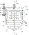
FIG. 1 is a front cross-sectional view of the present invention;
FIG. 2 is a cross-sectional view taken along line A-A of the present invention;
fig. 3 is an enlarged view of the structure of the present invention at B.
In the figure: 1-crushing box, 2-supporting plate, 3-driving machine I, 4-rotating shaft I, 5-gear, 6-sleeve, 7-first crushing blade, 8-external gear ring, 9-separating plate, 10-rotating shaft II, 11-stirring piece, 12-material adding port, 13-crushing piece, 14-material lifting mechanism, 15-discharging port, 16-stirring rod, 17-eccentric cylinder, 18-second crushing blade, 19-material lifting cylinder, 20-driving machine II, 21-spiral feeding shaft, 22-heater, 23-steam outlet and 24-electromagnetic control valve.
Detailed Description
The technical solutions in the embodiments of the present invention will be described clearly and completely with reference to the accompanying drawings in the embodiments of the present invention, and it is obvious that the described embodiments are only some embodiments of the present invention, not all embodiments. Based on the embodiments in the present invention, all other embodiments obtained by a person skilled in the art without creative work belong to the protection scope of the present invention.
Referring to fig. 1 to 3, the present invention provides a technical solution: pasture grass scattering equipment comprises a crushing box 1, wherein supporting legs are arranged at the bottom of the crushing box 1, a feed inlet is formed in the right side, close to the top, of the crushing box 1, a discharge outlet is formed in the bottom of the crushing box 1, a control valve is arranged on the discharge outlet, a supporting plate 2 is fixedly connected to the left side, close to the top, of the crushing box 1, a driving machine I3 is fixedly installed on the upper surface of the supporting plate 2 through a connecting frame, the driving machine I3 and the driving machine II 20 are of an integrated structure formed by installing a driving motor and a speed reducer, the arrangement of the speed reducer avoids overhigh rotating speed when the driving motor starts to be started, a rotating shaft I4 is fixedly connected to the output end of the driving machine I3, the rotating shaft I4 is rotatably connected with the supporting plate 2 through a bearing, a gear 5 is fixedly connected to the surface, close to, the inner wall of the circumference of the sleeve 6 is fixedly connected with a first crushing blade 7, the surface of the sleeve 6 close to the middle part thereof is fixedly connected with an outer gear ring 8, the inner wall of the crushing box 1 close to the middle part thereof is provided with an annular groove for the rotation of the outer gear ring 8, the gear 5 is meshed and connected with the outer gear ring 8, and the inner wall of the crushing box 1 close to the middle part thereof is fixedly connected with a partition plate 9.
Furthermore, the partition board 9 is obliquely arranged, a feed opening is formed in the upper surface of one side, close to the material lifting mechanism 14, of the partition board 9, an electromagnetic control valve 24 is arranged in the feed opening, and the oblique arrangement of the partition board 9 facilitates feeding of grass under the box through the electromagnetic control valve 24 and facilitates the grass crushed at the bottom of the partition board 9 to enter the material lifting barrel 19.
The top of the inner wall of the crushing box 1 is rotatably connected with a second rotating shaft 10 through a bearing, the second rotating shaft 10 is rotatably connected with the partition plate 9 through a bearing, and the second rotating shaft 10 is fixedly connected with a stirring piece 11 close to the bottom end of the second rotating shaft.
Further, stirring piece 11 includes three puddler 16, three puddler 16 fixed connection is close to on the surface of its bottom on two 10 of pivot, and three puddler 16 from the top down length reduces in proper order, the setting of three puddler 16 for the top of division board 9 is used for the forage grass to smash, the below then is used for the forage grass mixing, the forage grass after having avoided smashing need change different equipment and carry out the mixing processing, make the forage grass smash, the mixing integration is accomplished, the processing efficiency of forage grass has been improved.
Smash the right side that is close to its bottom on the case 1 and seted up material and added mouth 12, be close to the equal fixedly connected with belt pulley in surface on its top on pivot one 4 and the pivot two 10, and connect through belt transmission between two belt pulleys, be close to the surperficial fixedly connected with on its top on the pivot two 10 and smash piece 13, and smash piece 13 and be located sleeve 6.
Further, rubbing crusher 13 includes eccentric section of thick bamboo 17, be close to the fixed surface on its top on the inner wall of eccentric section of thick bamboo 17 and two 10 of pivot, the sword 18 is smashed to the circumference fixed surface of eccentric section of thick bamboo 17 is connected with the second, and first crushing sword 7 and the crisscross setting in second crushing sword 18 interval, driver one 3 drives pivot one 4 and rotates, thereby drive gear 5 and rotate, can drive sleeve 6 and rotate under outer ring gear 8's effect, thereby drive first crushing sword 7 and rotate, and can drive pivot two 10 and rotate under the effect of belt pulley and belt, pivot two 10 drive eccentric section of thick bamboo 17 and rotate, thereby it rotates to drive second crushing sword 18, and the rotation direction of first crushing sword 7 and the 18 of second crushing sword is opposite, make the crushing effect to the forage grass better under the effect of first crushing sword 7 and the 18 shearing force of second crushing sword.
The rear side of the crushing box 1 close to the middle of the crushing box is fixedly connected with a material lifting mechanism 14, one side of the material lifting mechanism 14 close to the top of the material lifting mechanism and close to the crushing box 1 is provided with a material outlet 15, one side of the material lifting mechanism 14 close to the bottom of the material lifting mechanism and close to the crushing box 1 is provided with a material inlet, and the material inlet is communicated with the crushing box 1.
Specifically, lifting mechanism 14 includes lifting cylinder 19, lifting cylinder 19 fixed connection is on smashing case 1 and is close to on the rear side at its middle part, lifting cylinder 19's top has driving machine two 20 through link fixed mounting, the link has played the fixed effect of support to driving machine two 20, lifting cylinder 19 inner wall's top is rotated through the bearing and is connected with spiral feeding shaft 21, spiral feeding shaft 21's top and driving machine two 20's output end fixed connection, bin outlet 15 and pan feeding mouth have all been seted up on lifting cylinder 19 is close to one side of smashing case 1.
Further, the equal fixedly connected with heater 22 in both sides around carrying the 19 inner wall of feed cylinder, carry feed cylinder 19 and be close to its top and keep away from one side of smashing case 1 and seted up steam outlet 23, and be equipped with the filter screen in the steam outlet 23, the filter screen has played the filter action, driver machine two 20 can drive spiral feeding shaft 21 and rotate, the grass is smashed the back in sleeve 6 and is fallen to division board 9 top surface naturally promptly, and slide to the pan feeding mouth, carry material mechanism 14 to promote again the grass that pan feeding mouth department gathered to sleeve 6 top, carry out the reciprocal crushing of circulation to the grass, and in the in-process that promotes through the setting of heater 22 and steam outlet 23, can carry out drying process to the grass.
The working principle is as follows: when the pasture grass scattering equipment is used, pasture grass is added into the crushing box 1 from the feeding hole, then the driving machine I3 and the driving machine II 20 are started, the driving machine I3 drives the rotating shaft I4 to rotate, so that the gear 5 is driven to rotate, the sleeve 6 is driven to rotate under the action of the outer gear ring 8, so that the first crushing blade 7 is driven to rotate, the rotating shaft II 10 is driven to rotate under the action of the belt pulley and the belt, the rotating shaft II 10 drives the eccentric cylinder 17 to rotate, so that the second crushing blade 18 is driven to rotate, the rotating directions of the first crushing blade 7 and the second crushing blade 18 are opposite, the crushing effect on the pasture grass is better under the shearing force of the first crushing blade 7 and the second crushing blade 18, the driving machine II 20 drives the spiral feeding shaft 21 to rotate, so that the pasture grass naturally falls to the top surface of the partition plate 9 after being crushed in the sleeve 6 and slides to the feeding hole, the lifting mechanism 14 lifts the pasture grass accumulated at the feeding hole, the pasture grass smashing and mixing machine comprises a pasture grass smashing device, a heater 22 and a steam outlet 23 are arranged in the process of lifting, the pasture grass smashing device can dry pasture grass, after the pasture grass smashing is completed, an electromagnetic control valve 24 is opened, feed or other pasture grass is added into a smashing box 1 through a material adding port 12, when the pasture grass above a partition plate 9 completely falls into the lower portion, a driving machine I3 is started, the electromagnetic control valve 24 is closed, a stirring rod 16 is used for stirring and mixing the pasture grass and the feed uniformly, the upper portion of the partition plate 9 is used for smashing the pasture grass, the lower portion of the partition plate 9 is used for uniformly mixing the pasture grass, the situation that the smashed pasture grass needs to be replaced with different devices for uniformly.
Although embodiments of the present invention have been shown and described, it will be appreciated by those skilled in the art that changes, modifications, substitutions and alterations can be made in these embodiments without departing from the principles and spirit of the invention, the scope of which is defined in the appended claims and their equivalents.
Claims (6)
1. The utility model provides a pasture grass equipment of breaing up, is including smashing case (1), the bottom of smashing case (1) is equipped with supporting leg, its characterized in that: the grinding box is characterized in that a supporting plate (2) is fixedly connected to the left side of the grinding box (1) close to the top of the grinding box, a first driving machine (3) is fixedly mounted on the upper surface of the supporting plate (2) through a connecting frame, a first rotating shaft (4) is fixedly connected to the output end of the first driving machine (3), the first rotating shaft (4) is rotatably connected with the supporting plate (2) through a bearing, a gear (5) is fixedly connected to the surface of the first rotating shaft (4) close to the bottom end of the first rotating shaft, a sleeve (6) with two open ends is rotatably connected to the inner wall of the grinding box (1) close to the top of the grinding box through a bearing, a first grinding blade (7) is fixedly connected to the circumferential inner wall of the sleeve (6), an outer gear ring (8) is fixedly connected to the surface of the sleeve (6) close to the middle of the grinding box, the gear (5), the top of the inner wall of the crushing box (1) is rotatably connected with a second rotating shaft (10) through a bearing, the surfaces of the first rotating shaft (4) and the second rotating shaft (10) close to the top end of the first rotating shaft are fixedly connected with belt pulleys and are connected with each other through belt transmission, the surface of the second rotating shaft (10) close to the bottom end of the second rotating shaft is fixedly connected with a stirring piece (11), the right side of the crushing box (1) close to the bottom of the crushing box is provided with a material adding port (12), the surface of the second rotating shaft (10) close to the top end of the second rotating shaft is fixedly connected with a crushing piece (13), the crushing piece (13) is positioned in a sleeve (6), the rear side of the crushing box (1) close to the middle of the crushing box is fixedly connected with a material lifting mechanism (14), one side of the lifting mechanism (14) close to the top of the crushing box and close to the crushing box (1) is provided with a material discharging port (15), one side of, and the feeding port is communicated with the crushing box (1).
2. Pasture grass scattering apparatus as claimed in claim 1, characterized in that: stirring piece (11) include three puddler (16), three puddler (16) fixed connection is close to on the surface of its bottom on pivot two (10), and three puddler (16) length from the top down reduces in proper order.
3. Pasture grass scattering apparatus as claimed in claim 1, characterized in that: the crushing piece (13) comprises an eccentric cylinder (17), the inner wall of the eccentric cylinder (17) is fixedly connected with the surface of the second rotating shaft (10) close to the top end of the second rotating shaft, the circumferential surface of the eccentric cylinder (17) is fixedly connected with a second crushing blade (18), and the first crushing blade (7) and the second crushing blade (18) are arranged in a staggered mode at intervals.
4. Pasture grass scattering apparatus as claimed in claim 1, characterized in that: the material lifting mechanism is characterized in that the partition plate (9) is obliquely arranged, a feed opening is formed in the upper surface, close to one side of the material lifting mechanism (14), of the partition plate (9), and an electromagnetic control valve (24) is arranged in the feed opening.
5. Pasture grass scattering apparatus as claimed in claim 1, characterized in that: carry material mechanism (14) including carrying material cylinder (19), carry material cylinder (19) fixed connection on smashing case (1) and being close to on the rear side at its middle part, the top of carrying material cylinder (19) has driving machine two (20) through link fixed mounting, the top of carrying material cylinder (19) inner wall is rotated through the bearing and is connected with spiral feeding shaft (21), the top of spiral feeding shaft (21) and the output fixed connection of driving machine two (20), bin outlet (15) and pan feeding mouth have all been seted up on one side that is close to smashing case (1) in carrying material cylinder (19).
6. Pasture grass scattering apparatus as claimed in claim 5, characterized in that: the equal fixedly connected with heater (22) in both sides around the lifting cylinder (19) inner wall, steam outlet (23) have been seted up to one side that lifting cylinder (19) are close to its top and keep away from crushing case (1), and are equipped with the filter screen in steam outlet (23).
Priority Applications (1)
| Application Number | Priority Date | Filing Date | Title |
|---|---|---|---|
| CN201921741511.3U CN210695914U (en) | 2019-10-17 | 2019-10-17 | Pasture scattering equipment |
Applications Claiming Priority (1)
| Application Number | Priority Date | Filing Date | Title |
|---|---|---|---|
| CN201921741511.3U CN210695914U (en) | 2019-10-17 | 2019-10-17 | Pasture scattering equipment |
Publications (1)
| Publication Number | Publication Date |
|---|---|
| CN210695914U true CN210695914U (en) | 2020-06-09 |
Family
ID=70939852
Family Applications (1)
| Application Number | Title | Priority Date | Filing Date |
|---|---|---|---|
| CN201921741511.3U Expired - Fee Related CN210695914U (en) | 2019-10-17 | 2019-10-17 | Pasture scattering equipment |
Country Status (1)
| Country | Link |
|---|---|
| CN (1) | CN210695914U (en) |
Cited By (5)
| Publication number | Priority date | Publication date | Assignee | Title |
|---|---|---|---|---|
| CN111567833A (en) * | 2020-06-19 | 2020-08-25 | 王廷斌 | Reducing mechanism for poultry fodder |
| CN111758403A (en) * | 2020-08-04 | 2020-10-13 | 熊钢 | Pasture scattering and cutting device for livestock breeding |
| CN111992277A (en) * | 2020-07-02 | 2020-11-27 | 宜兴市百粮农业科技有限公司 | Rice hulling device capable of being automatically controlled and detected |
| CN112021616A (en) * | 2020-08-20 | 2020-12-04 | 李小滨 | A granulator for feed production |
| CN115364729A (en) * | 2022-07-13 | 2022-11-22 | 江苏维尔克汽车内饰件有限公司 | Low-odor automobile interior trim part material resonance blending device and blending method |
-
2019
- 2019-10-17 CN CN201921741511.3U patent/CN210695914U/en not_active Expired - Fee Related
Cited By (7)
| Publication number | Priority date | Publication date | Assignee | Title |
|---|---|---|---|---|
| CN111567833A (en) * | 2020-06-19 | 2020-08-25 | 王廷斌 | Reducing mechanism for poultry fodder |
| CN111992277A (en) * | 2020-07-02 | 2020-11-27 | 宜兴市百粮农业科技有限公司 | Rice hulling device capable of being automatically controlled and detected |
| CN111992277B (en) * | 2020-07-02 | 2021-09-21 | 宜兴市百粮农业科技有限公司 | Rice hulling device capable of being automatically controlled and detected |
| CN111758403A (en) * | 2020-08-04 | 2020-10-13 | 熊钢 | Pasture scattering and cutting device for livestock breeding |
| CN112021616A (en) * | 2020-08-20 | 2020-12-04 | 李小滨 | A granulator for feed production |
| CN115364729A (en) * | 2022-07-13 | 2022-11-22 | 江苏维尔克汽车内饰件有限公司 | Low-odor automobile interior trim part material resonance blending device and blending method |
| CN115364729B (en) * | 2022-07-13 | 2023-08-22 | 江苏维尔克汽车内饰件有限公司 | Low-odor automobile interior trim material resonance blending device and blending method |
Similar Documents
| Publication | Publication Date | Title |
|---|---|---|
| CN210695914U (en) | Pasture scattering equipment | |
| CN208286148U (en) | A kind of livestock-raising device for feeding | |
| CN210298990U (en) | Feed feeding device is fed to fodder | |
| CN209549644U (en) | A kind of feed crushing drying discharging device | |
| CN109618695A (en) | A kind of aquaculture is with facilitating the automatic shredding facilities of discharge type forage | |
| CN212236923U (en) | Feed mixing device for healthy breeding of five-black chickens | |
| CN113926551A (en) | Pet food processing machine | |
| CN210906343U (en) | Fodder reducing mechanism for animal husbandry | |
| CN210641503U (en) | Pasture chopping device for animal husbandry | |
| CN209287414U (en) | A kind of anticlogging herding feed stuff reducing device | |
| CN209185114U (en) | A kind of livestock breed aquatics herbage grinding device | |
| CN215353199U (en) | Special fodder mixing machine of raiser | |
| CN108620203B (en) | Quick feed smashing and mixing device for animal husbandry | |
| CN209034431U (en) | Crusher for fodder is used in a kind of cultivation of mutton sheep | |
| CN208800008U (en) | A kind of chicken and duck breeding feed mixing arrangement | |
| CN215455295U (en) | Feed processing sieving mechanism with stoving function | |
| CN109328676A (en) | A kind of efficient livestock-raising herbage pulverizer | |
| CN212120126U (en) | Mixing stirring device for livestock feed | |
| CN212681207U (en) | Fodder processing machinery that facilitates use | |
| CN209676916U (en) | A kind of livestock breed aquatics timothy cutter device | |
| CN209393123U (en) | A kind of feed processing mixed stirring device for wild boar cultivation | |
| CN208449511U (en) | A kind of feed processing raw material grinding device of novel good crushing effect | |
| CN113141884A (en) | Forage crushing mixer for livestock breeding | |
| CN216322248U (en) | Poultry is with fodder grinder | |
| CN219051527U (en) | Fodder crushing mixer |
Legal Events
| Date | Code | Title | Description |
|---|---|---|---|
| GR01 | Patent grant | ||
| GR01 | Patent grant | ||
| CF01 | Termination of patent right due to non-payment of annual fee |
Granted publication date: 20200609 Termination date: 20211017 |
|
| CF01 | Termination of patent right due to non-payment of annual fee |