CN210685531U - Vertical circulation stereo garage - Google Patents
Vertical circulation stereo garage Download PDFInfo
- Publication number
- CN210685531U CN210685531U CN201921275641.2U CN201921275641U CN210685531U CN 210685531 U CN210685531 U CN 210685531U CN 201921275641 U CN201921275641 U CN 201921275641U CN 210685531 U CN210685531 U CN 210685531U
- Authority
- CN
- China
- Prior art keywords
- driving
- stereo garage
- wheel
- groups
- groove
- Prior art date
- Legal status (The legal status is an assumption and is not a legal conclusion. Google has not performed a legal analysis and makes no representation as to the accuracy of the status listed.)
- Active
Links
Images


Abstract
The utility model discloses a vertical circulation stereo garage belongs to the public facilities field. The vertical circulating stereo garage comprises a support arranged on a base, wherein a plurality of groups of parking frames are movably arranged on the support, the parking frames are connected with a circulating assembly, and the circulating assembly is connected with a driving mechanism through a transmission assembly; the base is also provided with a groove, a movable plate is rotationally arranged in the groove, and the movable plate is provided with two groups of limiting plates; and a telescopic component is arranged between the movable plate and the groove. The utility model discloses a set up rotatable fly leaf in the recess of base to and set up two sets of limiting plates on the fly leaf, alright drive the fly leaf through the flexible subassembly that has hollow post and activity post and rotate, make two sets of limiting plate displacements to the both sides that the car frame was deposited to the bottom, carry on spacingly with the car frame of depositing to the bottom, thereby can guarantee the security of getting the car and parkking, and be convenient for the vehicle business turn over deposit the car frame.
Description
Technical Field
The utility model relates to a public facilities field, concretely relates to vertical circulation stereo garage.
Background
The vertical circulating stereo garage is a parking system for completing vehicle parking and taking by making a vehicle parking frame do circulating motion on a vertical plane, has the advantages of small occupied area, convenience in operation, small field limitation and the like compared with the traditional garage, and is a future development trend.
However, the conventional vertical circulation stereo garage generally realizes the circulation motion of the existing car frame by matching a traction chain with a speed reduction driving motor, and generally has no self-locking function and poor stability. In addition, because the traditional vertical circulation stereo garage is not provided with an additional limiting mechanism to limit the parking frame to move, when a user parks or takes out the vehicle, the situation that the parking frame accidentally moves circularly can occur, and therefore, the potential safety hazard is great.
SUMMERY OF THE UTILITY MODEL
An object of the utility model is to provide a vertical circulation stereo garage to solve the problem that proposes among the above-mentioned background art.
In order to achieve the above object, the embodiment of the present invention provides the following technical solutions:
a vertical circulation stereo garage comprises a support arranged on a base, wherein a plurality of groups of parking frames are movably arranged on the support, the parking frames are connected with a circulation assembly, the circulation assembly is connected with a driving mechanism with a self-locking function through a transmission assembly, and the driving mechanism drives the circulation assembly to drive the parking frames to do circulation motion on a vertical plane; the base is also provided with a groove, a movable plate is rotationally arranged in the groove, and the movable plate is provided with two groups of limiting plates for limiting the car storage frame to do circular motion; and a telescopic assembly which is used for driving the movable plate to rotate and has a self-locking function is arranged between the movable plate and the groove.
The embodiment of the utility model adopts a preferred scheme, the circulating component comprises two groups of first driving wheels which are symmetrically arranged and two groups of second driving wheels which are symmetrically arranged, the two groups of first driving wheels are both arranged on a rotating shaft, the rotating shaft is rotationally arranged on a bracket, and the two groups of first driving wheels are respectively in transmission connection with the two groups of second driving wheels through two groups of traction components; the parking frame is arranged at the bottom of the mounting plate, the mounting plate is rotatably arranged between the two groups of movable blocks, and the two groups of movable blocks are respectively fixed on the two groups of traction members; the rotating shaft is connected with the driving mechanism through the transmission assembly, and the driving mechanism drives the transmission assembly to drive the rotating shaft to rotate.
The embodiment of the utility model provides an another kind of preferred scheme who adopts, the flashing is still installed at the top of support, the flashing be umbrella-shaped structure.
The embodiment of the utility model provides an another kind of preferred scheme who adopts, transmission assembly including from driving wheel and action wheel, the pivot with follow fixed linking to each other of driving wheel, follow driving wheel carry out the transmission through driving medium and action wheel and be connected, action wheel and actuating mechanism link to each other, actuating mechanism drive action wheel rotate.
The embodiment of the utility model provides an another kind of preferred scheme who adopts, actuating mechanism including rotating worm wheel and the worm that sets up, action wheel and worm wheel fixed link to each other, worm wheel and worm intermeshing, the worm link to each other with first motor, first motor install on the base.
According to another preferred scheme adopted by the embodiment of the utility model, the telescopic component comprises a hollow column and a movable column, and one end of the hollow column is rotatably arranged in the groove; the movable column is slidably arranged in the hollow column and penetrates through the hollow column to be rotatably connected with the movable plate; the hollow column is internally provided with a spiral transmission mechanism which is used for driving the movable column to slide and has a self-locking function.
In another preferred scheme adopted by the embodiment of the utility model, the screw transmission mechanism comprises a screw rod rotatably mounted in the hollow column, the movable column is provided with a threaded hole matched with the screw rod, and the threaded hole is in threaded connection with the screw rod; a limiting block is further fixed on the movable column, a limiting groove corresponding to the limiting block is formed in the inner wall of the hollow column, and the limiting block is in sliding fit with the limiting groove; the screw rod is fixedly connected with the driven bevel gear, the driven bevel gear is meshed with the driving bevel gear, and the driving bevel gear is connected with a second motor for driving the driving bevel gear to rotate.
The embodiment of the utility model provides an above-mentioned technical scheme compares in prior art, has following technological effect:
(1) the embodiment of the utility model provides a perpendicular circulation stereo garage has the circulation subassembly that pulls piece, first drive wheel and second drive wheel through the setting to and have the drive assembly from driving wheel and action wheel through the setting, alright drive the bicycle parking frame through the actuating mechanism who has worm wheel and worm and carry out stable cyclic motion on vertical plane, but also can guarantee that the bicycle parking frame that has the vehicle can not take place the gliding scheduling problem.
(2) The embodiment of the utility model provides a still set up rotatable fly leaf in the recess of base to and set up two sets of limiting plates on the fly leaf, alright drive the fly leaf through the flexible subassembly that has hollow post and activity post and rotate, make two sets of limiting plate displacements to the both sides that the frame was deposited to the bottommost layer, carry on spacingly with the frame of depositing to the bottommost layer, thereby can guarantee the security of getting car and parking, and be convenient for the vehicle business turn over deposit the frame.
Drawings
Fig. 1 is a schematic structural diagram of a vertical circulation stereo garage provided in embodiment 1.
Fig. 2 is a perspective view of a drive mechanism and a transmission assembly provided in embodiment 1.
Fig. 3 is a sectional view taken along line a-a in fig. 1.
Fig. 4 is a schematic structural diagram of the telescopic assembly and the screw transmission mechanism provided in embodiment 1.
Fig. 5 is a schematic structural diagram of a vertical circulation stereo garage provided in embodiment 2.
In the figure: 1-base, 2-bracket, 3-vehicle storage frame, 4-positioning plate, 5-mounting plate, 6-movable block, 7-traction piece, 8-first driving wheel, 9-second driving wheel, 10-rotating shaft, 11-driven wheel, 12-driving piece, 13-driving wheel, 14-worm wheel, 15-worm, 16-first motor, 17-movable plate, 18-limiting plate, 19-groove, 20-inclined plate, 21-hollow column, 22-movable column, 23-screw rod, 24-threaded hole, 25-limiting groove, 26-limiting block, 27-driven bevel gear, 28-driving bevel gear, 29-second motor, 30-rain shielding plate and 31-control cabinet.
Detailed Description
The following specific embodiments are specifically and clearly described in the technical solutions of the present application with reference to the drawings provided in the present specification. The drawings in the specification are for clarity of presentation of the technical solutions of the present application, and do not represent shapes or sizes in actual production or use, and reference numerals of the drawings are not limited to the claims involved.
In addition, in the description of the present application, terms used should be construed broadly, and specific meanings of the terms may be understood by those skilled in the art according to actual situations. For example, the term "mounted" as used in this application may be defined as a fixed mounting that is removable or a fixed mounting that is not removable, etc.; the terms "set" and "provided" as used herein may be defined as either a contact or a non-contact arrangement, etc.; the terms "connected" and "coupled" as used herein may be defined as mechanically, electrically, or both fixedly and removably coupled; the terms "first", "second", and the like are used for descriptive purposes only and are not to be construed as indicating or implying relative importance or implicitly indicating the number of technical features indicated; all the terms of orientation used are used with reference to the drawings or are based on the direction defined by the actual situation and the common general knowledge.
Example 1
Referring to fig. 1-4, the embodiment provides a vertical circulation stereo garage, which comprises a support 2, wherein the support 2 is fixedly arranged on a base 1. In addition, the support 2 on the activity be provided with a plurality of groups parking frame 3, parking frame 3 link to each other with the circulation subassembly, the circulation subassembly pass through drive assembly and link to each other with the actuating mechanism that has self-locking function, actuating mechanism drive circulation subassembly drive parking frame 3 carry out the cyclic motion on vertical plane.
Specifically, the circulating assembly comprises two groups of first driving wheels 8 which are symmetrically arranged and two groups of second driving wheels 9 which are symmetrically arranged, and the first driving wheels 8 and the second driving wheels 9 are both arranged on the bracket 2; the two groups of first driving wheels 8 are fixedly arranged on a rotating shaft 10, the rotating shaft 10 is rotatably arranged on the bracket 2, the two groups of first driving wheels 8 are respectively in transmission connection with two groups of second driving wheels 9 through two groups of traction parts 7, the traction parts 7 can adopt chains common in the prior art, and the second driving wheels 9 and the first driving wheels 8 can adopt chain wheels common in the prior art; the parking frame 3 is arranged at the bottom of the mounting plate 5, the mounting plate 5 is rotatably arranged between the two groups of movable blocks 6, and the two groups of movable blocks 6 are respectively fixed on the two groups of traction members 7; under the action of the gravity of the mounting plate 5 and the parking frame 3, the parking frame 3 is always vertically downward in the cyclic motion process; in addition, two sets of positioning plates 4 are fixed in the parking frame 3, so that the vehicle can be positioned, and the problem that the vehicle in the parking frame 3 inclines when the parking frame 3 circularly moves is solved.
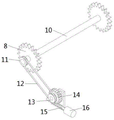
Further, the rotating shaft 10 is connected with a driving mechanism through a transmission assembly, and the driving mechanism drives the transmission assembly to drive the rotating shaft 10 to rotate. Specifically, the transmission assembly comprises a driven wheel 11 and a driving wheel 13, the rotating shaft 10 is fixedly connected with the driven wheel 11, and the driven wheel 11 is in transmission connection with the driving wheel 13 through a transmission piece 12; wherein, the driven wheel 11 and the driving wheel 13 can both adopt the belt pulley common in the prior art, and the transmission piece 12 can adopt the belt common in the prior art.
In addition, the driving wheel 13 is connected with a driving mechanism, and the driving mechanism drives the driving wheel 13 to rotate. Specifically, actuating mechanism include worm wheel 14 and the worm 15 of rotation installation on base 1, action wheel 13 and worm wheel 14 fixed link to each other, worm wheel 14 and worm 15 intermeshing, worm 15 and the motor shaft of first motor 16 fixed link to each other, first motor 16 install on base 1.
Wherein, first motor 16 can select for use the servo motor among the prior art, can drive worm 15 through first motor 16 and rotate, worm 15's rotation can drive worm wheel 14 and rotate, worm wheel 14's rotation can drive action wheel 13 and follow driving wheel 11 and rotate, follow driving wheel 11's rotation and can drive pivot 10 and rotate, pivot 10's rotation can drive first drive wheel 8 and draw 7 to rotate to can make the movable block 6 move along drawing 7, carry out the purpose of cyclic motion on the vertical face with the realization drive frame 3 of depositing.
Further, a groove 19 is further formed in the base 1, a movable plate 17 is arranged in the groove 19, and one end of the movable plate 17 is rotatably mounted in the groove 19; the movable plate 17 is provided with two groups of limiting plates 18 for limiting the car parking frame 3 to do circular motion so as to reduce the potential safety hazard when parking or taking the car. In addition, a telescopic assembly having a self-locking function and used for driving the movable plate 17 to rotate is arranged between the movable plate 17 and the groove 19.
Specifically, the telescopic assembly comprises a hollow column 21 and a movable column 22, wherein one end of the hollow column 21 is rotatably arranged in the groove 19; the movable column 22 is slidably arranged in the hollow column 21 and penetrates through the hollow column 21 to be rotatably connected with the movable plate 17; and a spiral transmission mechanism which is used for driving the movable column 22 to slide and has a self-locking function is also arranged in the hollow column 21.
Specifically, the screw transmission mechanism comprises a screw 23 rotatably mounted in the hollow column 21, the movable column 22 is provided with a threaded hole 24 matched with the screw 23, and the threaded hole 24 is in threaded connection with the screw 23; a limiting block 26 is further fixed on the movable column 22, a limiting groove 25 corresponding to the limiting block 26 is formed in the inner wall of the hollow column 21, and the limiting block 26 is in sliding fit with the limiting groove 25; the screw 23 is fixedly connected with a driven bevel gear 27, the driven bevel gear 27 is meshed with a driving bevel gear 28, and the driving bevel gear 28 is connected with a second motor 29 for driving the driving bevel gear 28 to rotate.
The second motor 29 is a normal and reverse rotation motor which is common in the prior art, the second motor 29 can drive the driving bevel gear 28 to rotate, the driving bevel gear 28 can rotate to drive the driven bevel gear 27 to rotate, the driven bevel gear 27 can rotate to drive the screw 23 to rotate, the screw 23 can rotate to drive the movable post 22 to slide, and the movable post 22 can slide to drive the movable plate 17 to rotate, so that the two groups of limiting plates 18 are displaced to two sides of the parking frame 3 at the bottommost layer, and the parking frame 3 at the bottommost layer is limited to ensure the safety of vehicle taking and parking; meanwhile, the movable plate 17 is in an inclined state, so that the vehicle can conveniently enter and exit the parking frame 3.
In addition, a sloping plate 20 is further installed at one end of the base 1, and the sloping plate 20 is of a right-angled triangular prism structure, so that a vehicle can smoothly enter and exit the vehicle storage frame 3 along the sloping plate 20 and the movable plate 17. It should be noted that the base 1 is further provided with a control cabinet 31, and the control cabinet 31 is the same as a control cabinet of a vertical circulation stereo garage in the prior art, and can be used for controlling the start and stop of the first motor 16 and the second motor 29.
Example 2
Referring to fig. 5, in order to make the garage have a function of shielding rain, the embodiment is improved on the basis of embodiment 1, specifically, a rain shielding plate 30 is further installed on the top of the support 2, and the rain shielding plate 30 is of an umbrella-shaped structure to play a role of shielding rain and sun.
To sum up, the embodiment of the utility model provides a perpendicular circulation stereo garage has the circulation subassembly that pulls 7, first drive wheel 8 and second drive wheel 9 through the setting to and have the drive assembly from driving wheel 11 and action wheel 13 through the setting, alright drive through the actuating mechanism who has worm wheel 14 and worm 15 and deposit frame 3 and carry out stable cyclic motion on vertical plane, and can also guarantee that the bicycle parking frame 3 that has the vehicle can not take place the gliding scheduling problem.
Additionally, the embodiment of the utility model provides a still set up rotatable fly leaf 17 through the recess 19 at base 1 to and set up two sets of limiting plate 18 on fly leaf 17, alright drive fly leaf 17 through the flexible subassembly that has hollow post 21 and activity post 22 and rotate, make two sets of limiting plate 18 displacement to the both sides that the car frame 3 was deposited to the bottom, it is spacing to deposit the car frame 3 to the bottom, thereby can guarantee the security of getting the car and parkking, and be convenient for the vehicle business turn over deposit the car frame 3.
It should be noted that the above embodiments are only specific and clear descriptions of technical solutions and technical features of the present application. However, to those skilled in the art, aspects or features that are part of the prior art or common general knowledge are not described in detail in the above embodiments.
In addition, the technical solutions of the present application are not limited to the above-described embodiments, and those skilled in the art should take the description as a whole, and the technical solutions in the embodiments may be appropriately combined, so that other embodiments that can be understood by those skilled in the art may be formed.
Claims (7)
1. A vertical circulation stereo garage comprises a support (2) arranged on a base (1), wherein a plurality of groups of car storage frames (3) are movably arranged on the support (2), and the car storage frames (3) are connected with a circulation assembly, and the vertical circulation stereo garage is characterized in that the circulation assembly is connected with a driving mechanism with a self-locking function through a transmission assembly, and the driving mechanism drives the circulation assembly to drive the car storage frames (3) to do circulation motion on a vertical plane; the base (1) is also provided with a groove (19), the groove (19) is internally provided with a movable plate (17) in a rotating way, and the movable plate (17) is provided with two groups of limiting plates (18) for limiting the car storage frame (3) to do a circulating motion; and a telescopic component which is used for driving the movable plate (17) to rotate and has a self-locking function is arranged between the movable plate (17) and the groove (19).
2. The vertical circulation stereo garage of claim 1, wherein the circulation assembly comprises two sets of first driving wheels (8) symmetrically arranged and two sets of second driving wheels (9) symmetrically arranged, the two sets of first driving wheels (8) are both mounted on a rotating shaft (10), the rotating shaft (10) is rotatably mounted on the support (2), and the two sets of first driving wheels (8) are in transmission connection with the two sets of second driving wheels (9) through two sets of traction members (7) respectively; the car storage frame (3) is arranged at the bottom of the mounting plate (5), the mounting plate (5) is rotatably arranged between the two groups of movable blocks (6), and the two groups of movable blocks (6) are respectively fixed on the two groups of traction members (7); the rotating shaft (10) is connected with a driving mechanism through a transmission assembly, and the driving mechanism drives the transmission assembly to drive the rotating shaft (10) to rotate.
3. The vertical circulation stereo garage according to claim 1 or 2, wherein a rain shield (30) is further installed on the top of the support frame (2), and the rain shield (30) has an umbrella-shaped structure.
4. The vertical circulation stereo garage of claim 2, wherein the transmission assembly comprises a driven wheel (11) and a driving wheel (13), the rotating shaft (10) is fixedly connected with the driven wheel (11), the driven wheel (11) is in transmission connection with the driving wheel (13) through a transmission member (12), the driving wheel (13) is connected with a driving mechanism, and the driving mechanism drives the driving wheel (13) to rotate.
5. The vertical circulation stereo garage of claim 4, wherein the driving mechanism comprises a worm wheel (14) and a worm (15) which are rotatably arranged, the driving wheel (13) is fixedly connected with the worm wheel (14), the worm wheel (14) is meshed with the worm (15), the worm (15) is connected with a first motor (16), and the first motor (16) is arranged on the base (1).
6. The vertical circulation stereo garage of claim 1, wherein the telescopic assembly comprises a hollow column (21) and a movable column (22), one end of the hollow column (21) is rotatably arranged in the groove (19); the movable column (22) is arranged in the hollow column (21) in a sliding manner and penetrates through the hollow column (21) to be connected with the movable plate (17) in a rotating manner; the hollow column (21) is also internally provided with a screw transmission mechanism which is used for driving the movable column (22) to slide and has a self-locking function.
7. The vertical circulation stereo garage of claim 6, wherein the screw driving mechanism comprises a screw rod (23) rotatably mounted in the hollow column (21), the movable column (22) is provided with a threaded hole (24) matched with the screw rod (23), and the threaded hole (24) is in threaded connection with the screw rod (23); a limiting block (26) is further fixed on the movable column (22), a limiting groove (25) corresponding to the limiting block (26) is formed in the inner wall of the hollow column (21), and the limiting block (26) is in sliding fit with the limiting groove (25); the screw rod (23) is fixedly connected with a driven bevel gear (27), the driven bevel gear (27) is meshed with a driving bevel gear (28), and the driving bevel gear (28) is connected with a second motor (29) for driving the driving bevel gear (28) to rotate.
Priority Applications (1)
| Application Number | Priority Date | Filing Date | Title |
|---|---|---|---|
| CN201921275641.2U CN210685531U (en) | 2019-08-08 | 2019-08-08 | Vertical circulation stereo garage |
Applications Claiming Priority (1)
| Application Number | Priority Date | Filing Date | Title |
|---|---|---|---|
| CN201921275641.2U CN210685531U (en) | 2019-08-08 | 2019-08-08 | Vertical circulation stereo garage |
Publications (1)
| Publication Number | Publication Date |
|---|---|
| CN210685531U true CN210685531U (en) | 2020-06-05 |
Family
ID=70892448
Family Applications (1)
| Application Number | Title | Priority Date | Filing Date |
|---|---|---|---|
| CN201921275641.2U Active CN210685531U (en) | 2019-08-08 | 2019-08-08 | Vertical circulation stereo garage |
Country Status (1)
| Country | Link |
|---|---|
| CN (1) | CN210685531U (en) |
Cited By (2)
| Publication number | Priority date | Publication date | Assignee | Title |
|---|---|---|---|---|
| CN111807248A (en) * | 2020-07-01 | 2020-10-23 | 温州市简弈科技有限公司 | Self-rotating circulating three-dimensional lifting transportation system |
| CN111980457A (en) * | 2020-08-17 | 2020-11-24 | 东北大学 | Vertical circulating type stereo garage |
-
2019
- 2019-08-08 CN CN201921275641.2U patent/CN210685531U/en active Active
Cited By (2)
| Publication number | Priority date | Publication date | Assignee | Title |
|---|---|---|---|---|
| CN111807248A (en) * | 2020-07-01 | 2020-10-23 | 温州市简弈科技有限公司 | Self-rotating circulating three-dimensional lifting transportation system |
| CN111980457A (en) * | 2020-08-17 | 2020-11-24 | 东北大学 | Vertical circulating type stereo garage |
Similar Documents
| Publication | Publication Date | Title |
|---|---|---|
| CN210685531U (en) | Vertical circulation stereo garage | |
| CN203221940U (en) | Display screen overturning mechanism | |
| CN206971842U (en) | Hold type AGV carriers and combined with its access | |
| CN209908048U (en) | Vertical circulation stereo garage with anti-shaking function | |
| CN112727183A (en) | Car carrying device of multilayer lifting and transverse moving parking equipment | |
| CN214222509U (en) | Rack lifting device for gear | |
| CN209145372U (en) | Stereo garage Integral rotary type comb teeth blank compensation apparatus | |
| CN213550549U (en) | Novel rocker transmission mechanism for compact shelf | |
| CN210948180U (en) | Synchronous transmission mechanism of sliding plug door | |
| CN213339116U (en) | License plate discernment all-in-one that can network instant use | |
| CN207260693U (en) | A kind of multi-storied garage entrance broach frame broach blank compensation apparatus | |
| CN207260689U (en) | Multi-storied garage entrance broach frame broach blank compensation apparatus | |
| CN109398540B (en) | Portable bicycle parking frame | |
| CN208310340U (en) | Double movable gantry parking equipments | |
| CN216974334U (en) | Slide rocking type scissor stereo garage | |
| CN217802635U (en) | Open rubber mixing mill with adjustable roller spacing | |
| CN114198700B (en) | Intelligent street lamp control device for traffic power saving | |
| CN110656795A (en) | Bicycle stereo garage | |
| CN209145369U (en) | A kind of rotary comb teeth blank compensation apparatus of stereo garage | |
| CN216406323U (en) | Inclined plane slider lifting type stereo garage car taking device | |
| CN214117873U (en) | Top-opening window gear structure suitable for intelligent greenhouse | |
| CN219602403U (en) | Universal travelling mechanism | |
| CN216746855U (en) | Be used for highway quality testing sampling device | |
| CN217812636U (en) | Three-dimensional double-layer automobile parking space | |
| CN218332887U (en) | Traffic safety equipment that stability is high |
Legal Events
| Date | Code | Title | Description |
|---|---|---|---|
| GR01 | Patent grant | ||
| GR01 | Patent grant | ||
| PE01 | Entry into force of the registration of the contract for pledge of patent right | ||
| PE01 | Entry into force of the registration of the contract for pledge of patent right |
Denomination of utility model: A vertical circulation three-dimensional garage Effective date of registration: 20220627 Granted publication date: 20200605 Pledgee: Zhangshu Shunyin Village Bank Co.,Ltd. Pledgor: JIANGXI AODECHUAN AUTOMATION TECHNOLOGY CO.,LTD. Registration number: Y2022980008992 |