CN210364183U - Multifunctional electric vehicle windshield - Google Patents
Multifunctional electric vehicle windshield Download PDFInfo
- Publication number
- CN210364183U CN210364183U CN201920904983.XU CN201920904983U CN210364183U CN 210364183 U CN210364183 U CN 210364183U CN 201920904983 U CN201920904983 U CN 201920904983U CN 210364183 U CN210364183 U CN 210364183U
- Authority
- CN
- China
- Prior art keywords
- electric vehicle
- windshield
- hinge
- connecting support
- rain shield
- Prior art date
- Legal status (The legal status is an assumption and is not a legal conclusion. Google has not performed a legal analysis and makes no representation as to the accuracy of the status listed.)
- Expired - Fee Related
Links
Images


Landscapes
- Body Structure For Vehicles (AREA)
Abstract
The utility model relates to a weather shield, in particular to multi-functional electric motor car weather shield. The structure of the wind-rain shield comprises a connecting support rod connected with a handlebar of an electric vehicle, wherein the upper end of the connecting support rod is hinged with a wind-rain shield cover body, the upper end of the connecting support rod is connected with a hinge limiting part, the lower part of the hinge limiting part is sleeved at the upper end of the connecting support rod, the upper part of the hinge limiting part is provided with a hinge shaft, and a limiting stop head is arranged on the hinge limiting part at one side of the hinge shaft; the side of the wind and rain shield body is provided with a T-shaped articulated element, the top of the T-shaped articulated element is hollow and is used for inserting and fixing the outer frame pipe body of the wind and rain shield body, and the center of the lower part of the T-shaped articulated element is provided with a hinge hole and is used for inserting the hinge shaft. The utility model discloses a multi-functional electric motor car windscreen, it can switch windscreen and rain shield state at any time as required to convenient operation, simple structure is more convenient for install and is changed.
Description
Technical Field
The utility model relates to a weather shield, in particular to multi-functional electric motor car weather shield.
Background
In the prior art, for a user of an electric vehicle, riding can be greatly influenced in severe weather such as strong wind or rain, the current method is to adopt a windshield or a rain shield independently or use a full-wrapping type windshield and a rain shield, the former has a single function and cannot adapt to various conditions, and the latter has a complex structure and a large volume, so that the whole vehicle is too bulky after being mounted on the electric vehicle, and much inconvenience is brought to driving.
Disclosure of Invention
In order to solve the problem of the prior art, the utility model provides a multi-functional electric motor car windscreen, it can switch windscreen and rain fender state at any time as required to convenient operation, simple structure is more convenient for install and is changed.
The utility model discloses the technical scheme who adopts as follows:
a multifunctional electric vehicle windshield wiper comprises a connecting support rod connected with an electric vehicle handlebar, wherein the upper end of the connecting support rod is hinged with a windshield wiper cover body, the upper end of the connecting support rod is connected with a hinge limiting part, the lower part of the hinge limiting part is sleeved at the upper end of the connecting support rod, the upper part of the hinge limiting part is provided with a hinge shaft, and a limiting stopper is arranged on the hinge limiting part at one side of the hinge shaft; the side of the wind and rain shield body is provided with a T-shaped articulated element, the top of the T-shaped articulated element is hollow and is used for inserting and fixing the outer frame pipe body of the wind and rain shield body, and the center of the lower part of the T-shaped articulated element is provided with a hinge hole and is used for inserting the hinge shaft.
And two limiting stop clamping grooves are respectively arranged on two sides of the lower part of the T-shaped hinge piece and are respectively used for locking the limiting stops in a windshield state and a rain shield state.
The connecting support rod is in a fold line shape.
The connecting support rod is arc-shaped.
The wind and rain shield body is a middle transparent cover body enclosed by the outer frame pipe body.
The wind and rain shield body is an opaque cover body enclosed by the outer frame pipe body, and a transparent visual window is arranged on one side of the opaque cover body.
The utility model provides a beneficial effect that technical scheme brought is:
the utility model discloses a multi-functional electric motor car windscreen, its windscreen cover body can be around the articulated shaft rotation with nearly 270 degrees to realize the rain fender of electric motor car overhead and the dual function of preceding windscreen, and it is convenient hard to switch, and the user just can switch two kinds of states use according to oneself needs very easily, and whole device passes through joint support pole direct mount in handlebar both sides, easy to assemble and dismantlement.
Drawings
In order to more clearly illustrate the technical solutions in the embodiments of the present invention, the drawings needed to be used in the description of the embodiments will be briefly described below, and it is obvious that the drawings in the following description are only some embodiments of the present invention, and it is obvious for those skilled in the art to obtain other drawings without creative efforts.
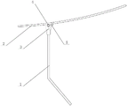
Fig. 1 is a schematic structural view of a windshield and a rain shield of a multifunctional electric vehicle (rain shield state);
fig. 2 is a schematic structural view (windshield state) of a multifunctional electric vehicle windshield of the present invention;
fig. 3 is the structural schematic diagram of the windshield cover of the utility model discloses a multifunctional electric vehicle windshield.
Detailed Description
In order to make the objects, technical solutions and advantages of the present invention clearer, embodiments of the present invention will be described in further detail below with reference to the accompanying drawings.
Example one
As shown in fig. 1 and 3, a multifunctional electric vehicle windshield wiper comprises a connecting support rod 1 connected with a handle bar of an electric vehicle, wherein the upper end of the connecting support rod 1 is hinged with a windshield wiper body 2, the upper end of the connecting support rod 1 is connected with a hinge limiting part 3, the lower part of the hinge limiting part 3 is sleeved at the upper end of the connecting support rod 1, the upper part of the hinge limiting part 3 is provided with a hinge shaft 4, and a limiting wiper 5 is arranged on the hinge limiting part 3 at one side of the hinge shaft 4; the side of the windshield cover body 2 be provided with T shape articulated elements 6, the top of T shape articulated elements 6 be cavity for it is fixed to alternate the outline body 21 of windshield cover body 2, the lower part center of T shape articulated elements 6 be provided with hinge hole 7, be used for alternating articulated shaft 4.
In this embodiment, two sides of the lower portion of the T-shaped hinge member 6 are respectively provided with a limiting stopper slot 61, and the two limiting stopper slots 61 are respectively used for locking the limiting stopper 5 in the windshield state and the rain blocking state.
As shown in fig. 1, this embodiment is a structural schematic diagram under the rain-proof state of multi-functional electric motor car windscreen, and at this moment, spacing dog 5 card on the articulated locating part 3 inlays in spacing dog draw-in groove 61 on the lower part right side of T-shaped articulated elements 6, and whole windscreen 2 crouches in the electric motor car top, plays the effect of sheltering from the rainwater.
As shown in the attached drawing 2, when the windshield state needs to be switched, the whole windshield cover body 2 is rotated along the hinge shaft 4, at the moment, the windshield cover body 2 rotates counterclockwise by 270 degrees approximately, until the limiting stopper 5 on the hinge limiting part 3 is stopped and locked by the limiting stopper clamping groove on the left side of the lower part of the T-shaped hinge part 6, and at the moment, the windshield cover body 2 is in a nearly vertical state and stands in front of the electric vehicle, so that the windshield state is formed.
As shown in fig. 1, the connecting support rod 1 in this embodiment is a polygonal line.
Example two
The difference between this embodiment and the first embodiment is that the connecting support rod 1 is arc-shaped.
EXAMPLE III
The difference between this embodiment and the first embodiment is that the windshield cover 2 is a middle transparent cover surrounded by the outer frame body 21.
Example four
The difference between this embodiment and the third embodiment is that the windshield cover 2 is an opaque cover surrounded by the outer frame body 21, and a transparent visual window is disposed on one side of the opaque cover.
The above description is only for the preferred embodiment of the present invention, and is not intended to limit the present invention, and any modifications, equivalent replacements, improvements, etc. made within the spirit and principle of the present invention should be included within the protection scope of the present invention.
Claims (6)
1. A multifunctional electric vehicle windshield wiper comprises a connecting support rod connected with an electric vehicle handlebar, wherein the upper end of the connecting support rod is hinged with a windshield wiper body; the side of the wind and rain shield body is provided with a T-shaped articulated element, the top of the T-shaped articulated element is hollow and is used for inserting and fixing the outer frame pipe body of the wind and rain shield body, and the center of the lower part of the T-shaped articulated element is provided with a hinge hole and is used for inserting the hinge shaft.
2. The multifunctional electric vehicle windshield wiper according to claim 1, wherein two sides of the lower part of the T-shaped hinge are respectively provided with a limiting wiper slot, and the two limiting wiper slots are respectively used for locking the limiting wipers in a windshield state and a rain state.
3. The multifunctional electric vehicle windshield according to claim 1, wherein the connecting support rod is in a zigzag shape.
4. The multifunctional electric vehicle windshield and rain shield as recited in claim 1, wherein the connecting support bar is arc-shaped.
5. The multifunctional electric vehicle windshield according to claim 1, wherein the windshield body is a middle transparent cover body surrounded by the outer frame tube body.
6. The multifunctional electric vehicle windshield and rain shield as recited in claim 1, wherein the windshield and rain shield body is an opaque body enclosed by the outer frame tube body, and a transparent visual window is arranged on one side of the opaque body.
Priority Applications (1)
| Application Number | Priority Date | Filing Date | Title |
|---|---|---|---|
| CN201920904983.XU CN210364183U (en) | 2019-06-14 | 2019-06-14 | Multifunctional electric vehicle windshield |
Applications Claiming Priority (1)
| Application Number | Priority Date | Filing Date | Title |
|---|---|---|---|
| CN201920904983.XU CN210364183U (en) | 2019-06-14 | 2019-06-14 | Multifunctional electric vehicle windshield |
Publications (1)
| Publication Number | Publication Date |
|---|---|
| CN210364183U true CN210364183U (en) | 2020-04-21 |
Family
ID=70265093
Family Applications (1)
| Application Number | Title | Priority Date | Filing Date |
|---|---|---|---|
| CN201920904983.XU Expired - Fee Related CN210364183U (en) | 2019-06-14 | 2019-06-14 | Multifunctional electric vehicle windshield |
Country Status (1)
| Country | Link |
|---|---|
| CN (1) | CN210364183U (en) |
-
2019
- 2019-06-14 CN CN201920904983.XU patent/CN210364183U/en not_active Expired - Fee Related
Similar Documents
| Publication | Publication Date | Title |
|---|---|---|
| CN210882459U (en) | Full-automatic dual-mode electric vehicle | |
| CN210364183U (en) | Multifunctional electric vehicle windshield | |
| CN105329362A (en) | Electric vehicle rearview mirror with wiper blade | |
| CN207889909U (en) | A kind of folding scooter | |
| CN106218771A (en) | Sunshade umbrella for bicycle | |
| CN210793448U (en) | Sunshade for electric vehicle | |
| CN202728432U (en) | Sunshade for bicycle and electric bicycle | |
| CN205686531U (en) | Hood front windshield dough cover supporting mechanism | |
| CN210707156U (en) | Rearview mirror for new energy automobile | |
| CN212828937U (en) | Extensible yacht windshield easy to assemble | |
| CN212172085U (en) | Truck rearview mirror with windshield wiper | |
| CN214396581U (en) | Support mounting structure of automobile outer rear-view mirror | |
| CN216424039U (en) | Bendable umbrella middle rod structure | |
| CN208429190U (en) | Electric vehicle solar protection devices | |
| CN204586794U (en) | A kind of Novel vehicle windshield wiper | |
| CN206446573U (en) | Commercial car wiper | |
| CN218805580U (en) | Automobile data recorder fixing base | |
| CN210063233U (en) | Multifunctional telescopic weather frame for two-wheel motorcycle | |
| CN216002889U (en) | Motorcycle windshield lifter and motorcycle | |
| CN217908858U (en) | Golf cart collapsible windshield of reassembling type of being convenient for | |
| CN206182456U (en) | Helmet rear -view mirror | |
| CN210364189U (en) | Rain protection mechanism for electric vehicle for designated driving | |
| CN2430049Y (en) | Two purpose foldalbe en-toutcas for humen and bike | |
| CN2442913Y (en) | Foldable booster for automobile steering wheel | |
| CN212125385U (en) | Rotary electric vehicle awning |
Legal Events
| Date | Code | Title | Description |
|---|---|---|---|
| GR01 | Patent grant | ||
| GR01 | Patent grant | ||
| CF01 | Termination of patent right due to non-payment of annual fee |
Granted publication date: 20200421 Termination date: 20200614 |
|
| CF01 | Termination of patent right due to non-payment of annual fee |