CN210348262U - Patrol and examine remote control system with protection in coordination of fire extinguishing system - Google Patents
Patrol and examine remote control system with protection in coordination of fire extinguishing system Download PDFInfo
- Publication number
- CN210348262U CN210348262U CN201921071106.5U CN201921071106U CN210348262U CN 210348262 U CN210348262 U CN 210348262U CN 201921071106 U CN201921071106 U CN 201921071106U CN 210348262 U CN210348262 U CN 210348262U
- Authority
- CN
- China
- Prior art keywords
- fire
- alarm
- scada
- protection
- monitoring computer
- Prior art date
- Legal status (The legal status is an assumption and is not a legal conclusion. Google has not performed a legal analysis and makes no representation as to the accuracy of the status listed.)
- Active
Links
Images

Abstract
The utility model relates to a patrol and examine remote control system cooperatively protected with a fire-fighting system, which comprises an SCADA system, a monitoring computer, a PLC system, a human-computer interface and a collecting device, wherein the SCADA system comprises the monitoring computer, the PLC system, the human-computer interface and the collecting device; the fire fighting system comprises a fire detector and a fire alarm controller, wherein the fire detector is used for acquiring the natural gas concentration, the gas transmission pipeline temperature and the smoke concentration in a fire-proof subarea and uploading the data to a monitoring computer; the fire alarm controller is in communication connection with the PLC system and used for outputting alarm signals when the concentration of natural gas, the temperature of a gas transmission pipeline or the concentration of smoke exceeds the limit, the alarm signals are displayed on a human-computer interface, and the monitoring computer controls the PLC system to control the running state of the field equipment according to the alarm signals. The utility model discloses the advantage can be with fire extinguishing system information access to station accuse SCADA system on, can show fire alarm system information like this on the SCADA system, make whole station accuse system information platform ization, can handle and station accuse system when the conflagration breaing out, accomplish to compromise to fire alarm processing and station accuse system processing.
Description
Technical Field
The utility model belongs to the technical field of the technique of natural gas transmission and distribution control and fire control warning and specifically relates to a patrol and examine remote control system with protection in coordination of fire extinguishing system.
Background
With economic development and environmental emphasis, natural gas has been widely used. An SCADA system, which is a supervisory control and data acquisition system with an industrial computer as a core, has gradually become the core of management and control of a pipeline system. The SCADA system has real-time and reliable acquisition capability and remote control capability, and can integrate real-time monitoring with an information system.
Meanwhile, as for the field of natural gas transmission and distribution, a fire alarm system is also indispensable, the existing fire alarm system and the station control system of a natural station are mutually independent systems, information is not communicated with each other, the station control system of the SCADA can be generally attended by people within 24 hours, but the fire alarm system is rarely attended by people in daily life, and only attended by people when alarming, when a fire alarm occurs, people think of dealing with the fire situation first, and neglect the related problem treatment of the station control system, such as: in the disposal of valves such as the natural gas shutoff valve, it is necessary to close the natural gas shutoff valve in accordance with the fire situation.
SUMMERY OF THE UTILITY MODEL
The utility model aims at providing a with fire extinguishing system protection in coordination patrol and examine remote control system can with fire extinguishing system information access to the station accuse SCADA system on, can show fire alarm system information on the SCADA system like this, make whole station accuse system information platform ization, can handle and station accuse system when taking place the conflagration, accomplish to take into account fire alarm.
The above utility model discloses an above-mentioned utility model purpose can realize through following technical scheme: an inspection remote control system cooperatively protected with a fire-fighting system comprises an SCADA system and a video monitoring system, wherein,
the SCADA system comprises a monitoring computer, a PLC system and a human-computer interface which are in communication connection with the monitoring computer, and an acquisition device for acquiring the operation data of the field equipment;
the fire fighting system comprises fire detectors and fire alarm controllers which are arranged in all fire protection subareas of a station yard, wherein each fire detector comprises at least one of an air sampling type smoke-sensing fire detector, a linear optical fiber temperature measurement fire detector and a combustible gas detector and a combination thereof, and is used for collecting the natural gas concentration, the gas transmission pipeline temperature and the smoke concentration in the fire protection subareas and uploading the data to a monitoring computer; the fire alarm controller is in communication connection with the PLC system and is used for outputting an alarm signal when the natural gas concentration, the gas transmission pipeline temperature or the smoke concentration exceeds the limit, the alarm signal is displayed on a human-computer interface, and the monitoring computer controls the PLC system to control the running state of the field equipment according to the alarm signal;
and the video monitoring system is used for monitoring the fire-proof subarea and the peripheral fire-proof subareas for alarming in real time when the fire-fighting system and/or the SCADA system receives the alarm signal.
The utility model discloses further set up to: in each fire-proof subarea, the optical fiber of the linear optical fiber temperature-measuring fire detector is laid on each natural gas transmission pipeline; the air sampling type smoke fire detector is dispersedly arranged in the fire-proof subarea; the combustible gas detector is respectively arranged on the interface of the gas transmission pipeline and the valve and is used for detecting leaked natural gas;
the monitoring computer sets preset values of natural gas concentration, gas transmission pipeline temperature and smoke concentration through a PLC system;
when the detected natural gas concentration exceeds a preset value, the fire alarm controller sends an alarm signal, the PLC system automatically controls the alarm subarea and the ventilation equipment of the adjacent fire subarea, the natural gas leakage degree is observed in real time through the flowmeter, and if the leakage speed or the leakage amount in unit time is greater than the preset value, the gas pipeline valve of the alarm subarea or the gas pipeline of the bypass alarm subarea is closed;
when the detected temperature of the gas transmission pipeline exceeds a preset value, the fire alarm controller sends out an alarm signal and gives out an alarm;
when the detected smoke concentration exceeds a preset value, the fire alarm controller sends out an alarm signal and gives out an alarm;
when the detected temperature of the gas pipeline and the smoke concentration of the corresponding fire prevention subarea exceed preset values, the fire alarm controller sends out an alarm signal, and the PLC system automatically controls to close the gas pipeline valve of the alarm subarea or the gas pipeline of the bypass alarm subarea.
The utility model discloses further set up to: the SCADA system also comprises at least one handheld inspection terminal distributed in each station, and the handheld inspection terminals are in wireless communication connection with the monitoring computer and used for sending alarm confirmation information to the monitoring computer and sending request signals for closing or bypassing any gas transmission pipeline to the monitoring computer.
The utility model discloses further set up to: the SCADA system further comprises at least one signal cable between every two adjacent fire-proof subareas and used for transmitting pulse information, the signal cables are connected to the PLC system through optical fiber ring networks respectively, and when the signal cables are disconnected completely, the human-computer interface gives an alarm.
The utility model discloses further set up to: the SCADA system further comprises wind direction and wind speed monitors which are arranged in each station and are in communication connection with a PLC system in the SCADA system, and the monitored wind direction and the monitored wind speed are displayed on a human-computer interface.
The utility model discloses further set up to: the inspection remote control system further comprises an emergency vehicle positioning display system, the emergency vehicle positioning display system comprises a GPS positioning module arranged on the emergency vehicle and an electronic map arranged on the monitoring computer, and when an alarm signal is received, the electronic map displays the running state and the pre-arrival time of the emergency vehicle in real time.
The utility model discloses further set up to: and the fire alarm controller is connected with a PLC system of the SCADA system through a field bus.
To sum up, the utility model discloses a beneficial technological effect does:
1. through on accessing station accuse SCADA system with the fire extinguishing system, can show fire information on the SCADA system, the video monitor system of cooperation station yard can make whole long-range accuse system information platform ization, the informationization of patrolling and examining, has improved conflagration emergency handling ability, and station accuse SCADA system can realize in addition with the linkage of fire extinguishing system, according to the size of the conflagration condition, whether automatic judgement needs to regulate and control station yard equipment, for example: the valves of the gas lines or bypass gas lines are closed, further improving fire handling capacity and efficiency.
2. By adopting signal cable monitoring and wind direction and wind speed monitoring by the wind direction and wind speed detector, the spreading trend of fire to surrounding fire prevention subareas can be judged, and the fire prevention subareas are provided for control personnel to make reasonable decisions.
Drawings
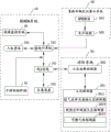
Fig. 1 is a system block diagram of one embodiment of the present invention;
fig. 2 is a system diagram of an embodiment of the present invention.
Reference numerals: 10. an SCADA system; 101. a hole monitoring computer; 102. a PLC system; 103. a human-machine interface; 104. a collection device; 20. a fire protection system; 201. a fire detector; 2011. an air sampling type smoke fire detector; 2012. a linear optical fiber temperature measurement fire detector; 2013. a combustible gas detector; 202. a fire alarm controller; 30. a video monitoring system; 40. the inspection terminal is held in hand; 50. an emergency vehicle positioning display system; 501. a GPS module; 502. an electronic map; 60. a wind direction and wind speed monitor; 70. a collection transmission module; 80. a signal cable.
Detailed Description
The present invention will be described in further detail with reference to the accompanying drawings.
Referring to fig. 1 and 2, the utility model discloses a patrol and examine remote control system with fire extinguishing system protection in coordination, including station accuse SCADA system 10, video monitor system 30, station accuse SCADA system 10, video monitor system 30 and fire extinguishing system 20 protection in coordination. The SCADA system 10 of each station yard can complete real-time data acquisition and monitoring control in the production process in the station yard, and simultaneously transmit the conditions and parameters of the equipment to the dispatching center through optical fibers and a public network, and can receive commands issued by the regulation and control center.
The station-controlled SCADA system 10 is capable of controlling the process equipment and auxiliary facilities of the whole station. The system mainly comprises a monitoring computer 101, a PLC system 102, a human-computer interface 103 and a collecting device 104, wherein the monitoring computer 101 is in communication connection with the PLC system 102 and can specifically use an industry standard or a protocol proprietary to a manufacturer, the human-computer interface 103 is used for providing station information for an operator, the station information is used as a schematic diagram of a control station and an alarm and event recording picture, and the human-computer interface 103 is connected with the monitoring computer 101 and is used for providing real-time operation data of field equipment collected by the collecting device 104 and driving a simulation diagram, an alarm display and a trend diagram. Alternatively, the monitoring computer 101 may be a PC computer, and the human-machine interface 103 is a part of the computer.
The fire protection system 20 may access information related to the fire protection system 20 to the PLC system 102 in the station-controlled SCADA via the fieldbus. The fire fighting system 20 includes fire detectors 201 disposed in fire zones of the station yard and fire alarm controllers 202 connected thereto via cables, and the fire detectors 201 mainly include at least one of smoke detectors, temperature-sensitive fire detectors, and combustible gas detectors, and combinations thereof. The fire alarm controller 202 is used for providing a stable working power supply for the fire detector 201 and receiving, converting and processing alarm signals output by the fire detector 201. The fire alarm controller 202 is connected with the PLC system 102 of the station-controlled SCADA system 10, and is configured to transmit an alarm signal to the PLC system 102, and obtain an alarm display on the human-computer interface 103, so that an operator can control the PLC system 102 to control an operation state of the field device according to the alarm display.
The video monitoring system 30 is connected to the monitoring computer 101, the video cameras installed in the fire zones can perform real-time monitoring, when the monitoring computer 101 receives an alarm signal, the real-time video monitoring can be called out, the alarm zones can be checked, whether a fire disaster occurs or not can be confirmed, and the fire condition can be judged.
Smoke fire detector can adopt air sampling formula smoke fire detector 201, and it can be according to the subregion size, and the equipartition adopts air sampling formula smoke fire detector 2011 in the fire prevention subregion, can realize surveying through absorbing the flue gas, and it generally divide into four working phase, is warning, action, fire 1 and fire 2 respectively, and it has more sensitive detection ability, does not receive environmental factor's influence, can not cause the wrong report to police. When the air sampling type smoke fire detector 201 detects that the smoke concentration is higher than the preset value, an alarm signal is output to the fire alarm controller 202, the fire alarm controller 202 transmits the alarm signal to the PLC system 102, and the human-computer interface 103 gives out a flash alarm of the alarm partition.
The temperature-sensing fire detector mainly comprises a linear optical fiber temperature-measuring fire detector 2012, which can more accurately determine the temperature distribution condition on the whole optical fiber according to the optical time domain reflection principle of the optical fiber and the back Raman scattering temperature effect of the optical fiber, thereby determining the abnormal high temperature or low temperature on the gas transmission pipeline, and visually seeing the temperature condition of each point on the optical fiber through the human-computer interface 103. When the linear optical fiber temperature measurement fire detector 2012 detects that the temperature of a certain point of the gas transmission pipeline exceeds a preset value, the fire alarm controller 202 outputs an alarm signal and gives an alarm, and a controller can observe the temperature conditions of all points of the gas transmission pipeline through the human-computer interface 103, judge an accident fault and make a decision.
In addition, because the influence of environmental factors exists at a certain point or a certain section of high temperature of the gas transmission pipeline, such as high temperature in summer, the local temperature of the gas transmission pipeline is overhigh, and a fire alarm false alarm is caused, so the SCADA system 10 is also provided with a function of comparing historical data, when the local high temperature alarm of the gas transmission pipeline occurs, a controller can call historical meteorological data and compare the temperature of the gas transmission pipeline under the same meteorological conditions, if the difference value between the actually detected gas transmission pipeline temperature and the historical gas transmission pipeline temperature is larger than a preset value under the same meteorological conditions, the high temperature abnormality of the gas transmission pipeline is judged, the human-computer interface 103 of the SCADA system 10 sends out a fire alarm, and the PLC system 102 controls the fire alarm controller 202 to send out an audible and visual alarm; if the difference value between the actually detected gas transmission pipeline temperature and the historical gas transmission pipeline temperature is smaller than the preset value, the local high temperature caused by the environmental factors is judged, and the control personnel can inform site personnel to process according to the historical processing method.
The combustible gas detector 2013 can respond to the concentration of leaked natural gas, and the combustible gas detector 2013 can be arranged in a fireproof partition, preferably, the combustible gas detector can be used for detecting leaked natural gas on an interface and a valve of an easily-leaked gas transmission pipeline. When the detected natural gas concentration exceeds a preset value, the fire alarm controller 202 transmits an alarm signal to the PLC system 102, the PLC system 102 automatically controls the alarm subarea and ventilation equipment in a fireproof subarea adjacent to the alarm subarea to start, the leakage condition of the natural gas is judged according to the flow condition of the flowmeter, and if the leakage speed and the leakage amount exceed the preset values, the alarm subarea and a gas pipeline valve or a bypass gas pipeline in the alarm subarea are closed.
In addition, when the detected smoke concentration exceeds the preset value and the temperature of the gas pipeline exceeds the preset value, the fire alarm controller 202 transmits an alarm signal to the PLC system 102, and the PLC system 102 automatically controls to close the gas pipeline valve or the bypass alarm sub-area of the alarm sub-area.
Further, the SCADA system 10 further includes at least one handheld inspection terminal 40 allocated to each station, and the handheld inspection terminal 40 is in wireless communication with the monitoring computer 101, and is configured to send alarm confirmation information to the monitoring computer 101 and send a request signal for closing or bypassing any gas transmission line to the monitoring computer 101.
Particularly, as the gas transmission pipeline is an important civil measure, how to prevent the false closing is ensured, the reliability and the accuracy of the system need to be concerned, and for the sent alarm signal, the fire hazard grade on site can be confirmed through at least one handheld inspection terminal 40 in each station, the on-site alarm information can be confirmed in time, and the on-site alarm information can be reported to the control personnel in time to be used as a basis for making decisions for the control personnel. The handheld inspection terminal 40 can be a mobile electronic device such as a mobile phone and a PAD. Meanwhile, the judgment of the fire situation is that a front-line worker in the station site has a clearer judgment, and the alarm information sent by the site handheld inspection terminal 40 can be set as the highest priority for judging whether to close the gas pipeline valve or the bypass gas pipeline, so that the front-line worker can request to close any gas pipeline or bypass. Preferably, in order to avoid misjudgment, each station yard may be equipped with two handheld inspection terminals 40, and when the two handheld inspection terminals 40 both determine the alarm information and send the same request, the monitoring computer 101 can receive the instruction, and the PLC controls the valve of the gas pipeline corresponding to the request to close or bypass the gas pipeline.
Furthermore, in order to provide more decision bases for the control personnel, the inspection remote control system further comprises an emergency vehicle positioning display system 50 which comprises a GPS positioning module arranged on each emergency vehicle and an electronic map 502 arranged on the monitoring computer 101 or other PCs, and when receiving the alarm signal, the control personnel can call the electronic map 502 out to display the running state and the pre-arrival time of the emergency vehicle in real time.
In another embodiment, the SCADA system 10 may further include at least one signal line disposed between each adjacent fire-protection sub-area for transmitting pulse information, and the at least one signal cable 80 is respectively connected to the PLC system 102 through a fiber ring network to determine whether the fire condition tends to spread toward the adjacent fire-protection sub-area.
Specifically, two signal lines arranged in adjacent fire zones are connected through the acquisition and transmission module 70, and the acquisition and transmission module 70 is used for monitoring pulse information, uploading the monitored pulse information to the monitoring computer 101, and displaying the pulse information on the human-computer interface 103. When the signal cables 80 are monitored to normally transmit information, the display state of the man-machine interface 103 is normal, when one signal cable 80 is disconnected, the man-machine interface 103 displays fire spread, and the positions of the disconnected signal cables 80 relative to all fire zones can be seen on the man-machine interface 103, so that the fire spread to the fire zone on the disconnected side of the signal cable 80 can be basically judged.
Furthermore, in order to make the fire spreading trend more clear, the SCADA system 10 further includes wind direction and wind speed monitors 60, a plurality of wind direction and wind speed monitors 60 are disposed around the station to monitor the wind direction and wind speed of the station in real time, the wind direction and wind speed monitors 60 are in communication connection with the PLC system 102, and display the wind direction and wind speed in real time on the human-computer interface 103. Through combining wind direction detection with signal cable 80 monitoring, can give the basis that the control personnel judged the conflagration and spread, it is the same with the wind direction to cut off one side when signal cable 80, then judges that the conflagration spreads to adjacent subregion, in time controls the valve of closing the gas line of adjacent subregion or the gas line of the adjacent subregion of bypass.
The utility model discloses a theory of operation does:
s101, collecting operation data of the field equipment by a collecting device 104; the operating data includes operating parameters of the device and various actuators, such as: the state of the valve, the collected operational data can be displayed on the human machine interface 103.
S102, the combustible gas detector 2013, the linear optical fiber temperature-sensing fire detector 2012 and the air sampling type smoke-sensing fire detector 2011 in the fire detector 201 correspondingly detect the natural gas concentration, the gas transmission line temperature and the smoke concentration in each fire-proof subarea of the station yard, when the natural gas concentration, the gas transmission line temperature or the smoke concentration in an area exceed the limit, an alarm signal is output, the monitoring computer 101 controls the PLC system 102 to control the running state of field equipment according to the alarm signal, and meanwhile, the alarm signal is displayed on the human-computer interface 103.
When the fire fighting system 20 and/or the SCADA system 10 receives the alarm signal, the video monitoring system 30 monitors the alarm fire zone and the surrounding fire zones in real time.
Furthermore, the station is divided into a plurality of fire-proof subareas, and a linear optical fiber temperature measuring detector is laid on each gas transmission pipeline in each protection subarea; a plurality of air sampling type smoke detectors are dispersedly arranged in each fire-proof subarea; a combustible gas detector 2013 is arranged on the interface and the valve of each gas transmission pipeline respectively and used for detecting leaked natural gas; the monitoring computer 101 sets preset values of natural gas concentration, gas pipeline temperature and regional smoke concentration through the PLC system 102;
when the detected natural gas concentration exceeds a preset value, the fire alarm controller 202 sends an alarm signal, the PLC system 102 automatically controls ventilation equipment of an alarm subarea and an adjacent fire-proof subarea, observes the natural gas leakage degree in real time through a flowmeter, and closes a gas pipeline valve of the alarm subarea or a gas pipeline of a bypass alarm subarea if the leakage speed or the leakage amount in unit time is greater than the preset value;
when the detected gas pipeline temperature exceeds a preset value, the fire alarm controller 202 sends out an alarm signal and gives out an alarm, and meanwhile, the human-computer interface 103 displays the alarm subarea position and the real-time gas pipeline temperature;
when the detected smoke concentration exceeds a preset value, the fire alarm controller 202 sends out an alarm signal and gives out an alarm, and meanwhile, the human-computer interface 103 displays the alarm partition position and the real-time smoke concentration;
when the detected temperature of the gas pipeline and the smoke concentration of the corresponding fire-prevention subarea exceed preset values, the fire alarm controller 202 sends out an alarm signal, and the PLC control system automatically closes the gas pipeline valve of the alarm subarea or the gas pipeline of the bypass alarm subarea.
Furthermore, at least one signal line is erected between each two adjacent fire-proof subareas for transmitting pulse information, the signal cable 80 is connected to the PLC system 102 through an optical fiber ring network, and when the signal cable 80 is disconnected, the PLC outputs an alarm signal and displays the position of the disconnected signal cable 80 on the human-computer interface 103; in addition, the wind direction and the wind speed in the station are monitored in real time through the wind direction and wind speed detector and displayed on the human-computer interface 103, whether a fire disaster spreads to an adjacent fire-proof subarea or not is judged according to the position of the disconnected signal line and the real-time wind direction, and a controller closes or bypasses the gas transmission line of the adjacent fire-proof subarea on the side of the disconnected signal line according to the judgment.
Furthermore, the responsible person of each station holds the inspection terminal 40, confirms the alarm information of the alarm subarea to the monitoring computer 101, and sends a request signal for closing any gas transmission line or bypassing the gas transmission line to the monitoring computer 101 according to the fire situation on site.
The utility model discloses a with natural gas station accuse SCADA system 10 with fire extinguishing system 20 contact together, make station accuse SCADA system 10 with fire extinguishing system 20 informationization, the integration, can show the information of fire extinguishing system 20 on station accuse SCADA system 10 like this, in addition, station accuse SCADA system 10 can also realize with fire extinguishing system 20's linkage, can enough play the condition of effect at fire extinguishing system 20 according to alarm information under, station accuse SCADA system 10 can judge according to detected data, the condition of a fire, regulate and control through equipment in each fire prevention subregion of PLC system 102 in the station yard, in order to cooperate fire control relief; in addition, through the matching of the signal cable 80 monitoring and the wind direction and wind speed monitoring instrument 60, the fire spreading can be judged more reliably by the control personnel, so that the opening and closing of the gas pipeline can be controlled in time; through the scheme, effective monitoring on the natural gas station can be guaranteed on the whole, misclosing of the gas transmission pipeline caused by misjudgment is prevented when a fire disaster happens, reliability and accuracy of a system are guaranteed, and benefits of users are protected.
The embodiment of this specific implementation mode is the preferred embodiment of the present invention, not limit according to this the utility model discloses a protection scope, so: all equivalent changes made according to the structure, shape and principle of the utility model are covered within the protection scope of the utility model.
Claims (6)
1. The utility model provides a patrol and examine remote control system with protection in coordination of fire extinguishing system which characterized in that: comprises a SCADA system (10) and a video monitoring system (30), wherein,
the SCADA system (10) comprises a monitoring computer (101), a PLC system (102) and a human-computer interface (103), wherein the PLC system and the human-computer interface are in communication connection with the monitoring computer (101), and a collecting device (104) is used for collecting operation data of field equipment;
the fire protection system (20) comprises fire detectors (201) and fire alarm controllers (202) which are arranged in fire zones of a station yard, wherein the fire detectors (201) comprise at least one of an air sampling type smoke-sensing fire detector (2011), a linear optical fiber temperature-measuring fire detector (2012) and a combustible gas detector (2013) and a combination thereof, and are used for collecting the natural gas concentration, the gas transmission line temperature and the smoke concentration in the fire zones and uploading the data to a monitoring computer (101); the fire alarm controller (202) is in communication connection with the PLC system (102) and is used for outputting an alarm signal when the concentration of natural gas, the temperature of a gas transmission pipeline or the concentration of smoke exceeds the limit, the alarm signal is displayed on a human-computer interface (103), and a monitoring computer (101) controls the PLC system (102) to control the running state of field equipment according to the alarm signal;
the video monitoring system (30) is used for monitoring the fire-fighting subarea with alarm and the surrounding fire-fighting subarea in real time when the fire-fighting system (20) and/or the SCADA system (10) receives the alarm signal.
2. The inspection and remote control system with fire protection system cooperative protection of claim 1, wherein: the SCADA system (10) further comprises at least one handheld inspection terminal (40) distributed in each station, wherein the handheld inspection terminals (40) are in wireless communication connection with the monitoring computer (101) and used for sending alarm confirmation information to the monitoring computer (101) and sending request signals for closing or bypassing any gas transmission pipeline to the monitoring computer (101).
3. The inspection and remote control system with fire protection system cooperative protection of claim 1, wherein: the SCADA system (10) further comprises at least one signal cable (80) between each two adjacent fire-proof subareas for transmitting pulse information, the signal cables (80) are respectively connected to the PLC system (102) through optical fiber ring networks, and when the signal cables (80) are completely disconnected, the man-machine interface (103) gives an alarm.
4. The inspection and remote control system with fire protection system cooperative protection of claim 3, wherein: the SCADA system (10) further comprises wind direction and wind speed monitors (60) which are arranged in each station and are in communication connection with the PLC system (102) in the SCADA system (10), and the monitored wind direction and wind speed are displayed on the human-computer interface (103).
5. The inspection and remote control system with fire protection system cooperative protection of claim 1, wherein: the inspection remote control system further comprises an emergency vehicle positioning display system (50), the emergency vehicle positioning display system (50) comprises a GPS positioning module arranged on the emergency vehicle and an electronic map (502) arranged on the monitoring computer (101), and when an alarm signal is received, the electronic map (502) displays the running state and the pre-arrival time of the emergency vehicle in real time.
6. The inspection and remote control system with fire protection system cooperative protection of claim 1, wherein: the fire alarm controller (202) is connected with a PLC system (102) of the SCADA system (10) through a field bus.
Priority Applications (1)
| Application Number | Priority Date | Filing Date | Title |
|---|---|---|---|
| CN201921071106.5U CN210348262U (en) | 2019-07-09 | 2019-07-09 | Patrol and examine remote control system with protection in coordination of fire extinguishing system |
Applications Claiming Priority (1)
| Application Number | Priority Date | Filing Date | Title |
|---|---|---|---|
| CN201921071106.5U CN210348262U (en) | 2019-07-09 | 2019-07-09 | Patrol and examine remote control system with protection in coordination of fire extinguishing system |
Publications (1)
| Publication Number | Publication Date |
|---|---|
| CN210348262U true CN210348262U (en) | 2020-04-17 |
Family
ID=70194292
Family Applications (1)
| Application Number | Title | Priority Date | Filing Date |
|---|---|---|---|
| CN201921071106.5U Active CN210348262U (en) | 2019-07-09 | 2019-07-09 | Patrol and examine remote control system with protection in coordination of fire extinguishing system |
Country Status (1)
| Country | Link |
|---|---|
| CN (1) | CN210348262U (en) |
Cited By (1)
| Publication number | Priority date | Publication date | Assignee | Title |
|---|---|---|---|---|
| CN110515340A (en) * | 2019-07-09 | 2019-11-29 | 深圳市中燃科技有限公司 | A kind of inspection remote power feeding system and its method cooperateing with protection with fire-fighting system |
-
2019
- 2019-07-09 CN CN201921071106.5U patent/CN210348262U/en active Active
Cited By (1)
| Publication number | Priority date | Publication date | Assignee | Title |
|---|---|---|---|---|
| CN110515340A (en) * | 2019-07-09 | 2019-11-29 | 深圳市中燃科技有限公司 | A kind of inspection remote power feeding system and its method cooperateing with protection with fire-fighting system |
Similar Documents
| Publication | Publication Date | Title |
|---|---|---|
| CN110515340B (en) | Inspection remote control system and method for cooperative protection with fire-fighting system | |
| CN106097642B (en) | A kind of city integrated piping lane intelligent monitoring and warning device | |
| CN210091331U (en) | Fire safety integration system | |
| CN112619016B (en) | Fire control monitored control system and management platform based on fire control gas cylinder | |
| CN111145482A (en) | Fire control command control system | |
| CN110732109A (en) | automatic monitoring devices of marine fire control steel bottle pressure that puts out a fire | |
| CN213781155U (en) | Cable pit calamity intelligent monitoring and processing system | |
| CN111800489A (en) | Wisdom fire control remote monitering system | |
| CN108918781A (en) | A kind of hydrogen sulfide gas on-line monitoring system | |
| KR20160010896A (en) | Smart fire-fighting management system for cultural assets and method thereof | |
| CN114705959A (en) | Power cable and channel on-line monitoring system | |
| CN210348262U (en) | Patrol and examine remote control system with protection in coordination of fire extinguishing system | |
| CN112216059A (en) | Fire control information management platform equipment based on thing networking | |
| CN204485168U (en) | A kind of fire-fighting automatic inspection device | |
| CN111292441A (en) | Fire-fighting equipment maintenance inspection method | |
| CN113833512A (en) | Intelligent monitoring operation method and system for tunnel fire fighting | |
| CN211656391U (en) | Cable trench monitoring system | |
| CN103941785A (en) | Method for controlling intelligent control device for power distribution station environment | |
| CN211906465U (en) | Circuit breaker with fire-fighting power supply monitoring and fire alarm functions | |
| KR20200080579A (en) | Fire detection control system and the method using skada program | |
| CN113181586A (en) | Data mining system and method for fire-fighting facility fault analysis | |
| CN216145264U (en) | Utility tunnel reports to police and supervises device | |
| CN116189370A (en) | Graded processing method for early warning information of fire-fighting equipment of transformer substation | |
| CN202649804U (en) | Centralized control system for communication base station | |
| CN213545078U (en) | Comprehensive intelligent supervision system for transformer substation environment |
Legal Events
| Date | Code | Title | Description |
|---|---|---|---|
| GR01 | Patent grant | ||
| GR01 | Patent grant |