CN210303964U - Crushing and compressing device for refuse landfill - Google Patents
Crushing and compressing device for refuse landfill Download PDFInfo
- Publication number
- CN210303964U CN210303964U CN201921006697.8U CN201921006697U CN210303964U CN 210303964 U CN210303964 U CN 210303964U CN 201921006697 U CN201921006697 U CN 201921006697U CN 210303964 U CN210303964 U CN 210303964U
- Authority
- CN
- China
- Prior art keywords
- crushing
- compressing device
- refuse
- compression
- bin
- Prior art date
- Legal status (The legal status is an assumption and is not a legal conclusion. Google has not performed a legal analysis and makes no representation as to the accuracy of the status listed.)
- Active
Links
Images

Landscapes
- Processing Of Solid Wastes (AREA)
Abstract
The utility model discloses a crushing and compressing device for a refuse landfill, which comprises a refuse inlet, a compressing device body and a transmission bin, the upper end of the compression device body is provided with a garbage inlet, the lower end in the garbage inlet is provided with a crushing roller set, one end of the crushing roller group is provided with a first rotating motor in a transmission way, the lower end of the garbage inlet is provided with a compression bin, the lower end of one side surface of the compression bin is provided with a pressure sensor, the lower end of the pressure sensor is provided with a shaft-driven bottom plate in a shaft-driven manner, a transmission bin is arranged on one side of the shaft-driven bottom plate, a processor is fixedly arranged at the upper end in the transmission bin, garbage through with needing the compression drops into through rubbish entry, and first rotating electrical machines drives crushing roller set and smashes rubbish such as easy open can through surperficial crushing cutting piece, has reduced the pressure to the garbage compression, owing to smash into the fritter to the degree of difficulty of compression has been reduced.
Description
Technical Field
The utility model relates to a refuse treatment technique especially relates to a landfill is with smashing compressor arrangement.
Background
The refuse landfill is a refuse centralized stacking site adopting a sanitary landfill mode, and the refuse sanitary landfill is widely applied in China due to low cost and good sanitary degree. The largest domestic refuse landfill is the Guangzhou Xingfeng refuse landfill, and the daily treatment of domestic refuse is about 7000 tons.
With the implementation of the policy of garbage classification, more and more recyclable garbage can be recycled, such as waste paper, plastic bottles, pop cans and the like, and particularly, metal materials such as pop cans and the like have high recycling performance, but if the waste paper is not compressed, the waste paper is too large in size and inconvenient to transport, so that a crushing and compressing device for a garbage landfill is urgently needed.
SUMMERY OF THE UTILITY MODEL
The to-be-solved technical problem of the utility model is to overcome current defect, provide a rubbish landfill is with smashing compressor arrangement to solve above-mentioned problem.
In order to achieve the above object, the utility model provides a following technical scheme: a crushing and compressing device for a refuse landfill comprises a refuse inlet, a compressing device body and a transmission bin, wherein the upper end of the compressing device body is provided with the refuse inlet, the lower end inside the refuse inlet is provided with a crushing roller group, one end of the crushing roller group is provided with a first rotating motor in a transmission manner, the lower end of the refuse inlet is provided with the compression bin, the lower end of one side surface of the compression bin is provided with a pressure sensor, the lower end of the pressure sensor is provided with a shaft-driven bottom plate in a shaft-driven manner, one side of the shaft-driven bottom plate is provided with the transmission bin, the upper end inside the transmission bin is fixedly provided with a processor, one side surface of the transmission bin is fixedly provided with a hydraulic machine, one side surface of the hydraulic machine is provided with a hydraulic rod in a transmission manner, one end of the hydraulic rod is fixedly provided, the inside lower extreme side fixed surface of compressor arrangement body is equipped with the second rotating electrical machines, the transmission of second rotating electrical machines one side is equipped with the threaded rod, the threaded rod surface is equipped with the nut, the axle action is equipped with the axle and moves the connecting rod on the nut, compressor arrangement body one side surface is equipped with the rubbish export, compressor arrangement body opposite side surface is equipped with the observation window.
As an optimal technical scheme of the utility model, crushing roller group comprises two crushing rollers, and every crushing roller surface all is equipped with a plurality of and smashes the cutting piece, and two crushing rollers pass through gear engagement and connect.
As a preferred technical scheme of the utility model, the nut passes through slider sliding connection in slide rail surface, and nut and threaded rod threaded connection.
As a preferred technical scheme of the utility model, pressure sensor and treater input electric connection, second rotating electrical machines, hydraulic press and first rotating electrical machines all with treater output electric connection.
As a preferred technical scheme of the utility model, the treater model is Siemens 6ES7517-3AP00-0AB0 central processing unit, and the pressure sensor model is SDE1-D10-G2-W18-L-P1-M12 pressure sensor.
As an optimized technical scheme of the utility model, compressor arrangement body surface is equipped with switch button and hydraulic press start button.
Compared with the prior art, the beneficial effects of the utility model are that: the crushing and compressing device for the refuse landfill site has the advantages that refuse to be compressed is thrown in through the refuse inlet, the first rotating motor drives the crushing roller set to crush refuse such as ring-pull cans through the crushing and cutting piece on the surface, the pressure for compressing the refuse is reduced, the refuse is crushed into small blocks, the difficulty of compression is reduced, when the pressing is completed, the processor controls the compression plate to reset, the pressure sensor senses the pressure to be reduced, the processor controls the second rotating motor to rotate at the moment, the threaded rod drives the nut to move, the sliding block slides back and forth on the surface of the sliding rail, the movement is kept stable, the shaft-driven bottom plate is driven to rotate back and forth under the action of the shaft-driven connecting rod, the compressed refuse slides down on the surface of the conveying belt and is discharged through the refuse outlet, the compressed refuse is convenient to discharge, the compression efficiency is improved, the refuse does not need to be taken out manually, the labor intensity is reduced, the structure is scientific and reasonable, the use is safe and convenient, and great help is provided for people.
Drawings
The accompanying drawings are included to provide a further understanding of the invention, and are incorporated in and constitute a part of this specification, illustrate embodiments of the invention, and together with the description serve to explain the invention and not to limit the invention. In the drawings:
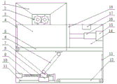
FIG. 1 is a schematic view of the internal structure of a crushing and compressing device for a refuse landfill according to the present invention;
FIG. 2 is a schematic view of a three-dimensional structure of a crushing and compressing device for a refuse landfill according to the present invention;
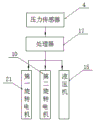
FIG. 3 is a schematic view of the principle structure of a crushing and compressing device for a refuse landfill according to the present invention;
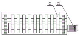
fig. 4 is a schematic top view of a crushing roller set of the crushing and compressing device for the refuse landfill according to the present invention;
in the figure: 1. a waste inlet; 2. a crushing roller set; 3. compressing the bin; 4. a pressure sensor; 5. a shaft-driven bottom plate; 6. a shaft-driven connecting rod; 7. a nut; 8. a slider; 9. a threaded rod; 10. a second rotating electrical machine; 11. a slide rail; 12. a conveyor belt; 13. a waste outlet; 14. a transmission bin; 15. a hydraulic press; 16. a hydraulic lever; 17. a processor; 18. a compression plate; 19. an observation window; 20. a compression device body; 21. a first rotating electrical machine.
Detailed Description
The technical solution in the embodiments of the present invention will be clearly and completely described below with reference to the drawings in the embodiments of the present invention, and it is obvious that the described embodiments are only some embodiments of the present invention, rather than all embodiments, and all other embodiments obtained by a person of ordinary skill in the art without creative work belong to the protection scope of the present invention based on the embodiments of the present invention.
Referring to fig. 1-4, the present invention provides a technical solution: a crushing and compressing device for a refuse landfill comprises a refuse inlet 1, a compressing device body 20 and a transmission bin 14, wherein the upper end of the compressing device body 20 is provided with the refuse inlet 1, the lower end inside the refuse inlet 1 is provided with a crushing roller group 2, one end of the crushing roller group 2 is provided with a first rotating motor 21 in a transmission manner, the lower end of the refuse inlet 1 is provided with a compression bin 3, the lower end of one side surface of the compression bin 3 is provided with a pressure sensor 4, the lower end of the pressure sensor 4 is provided with a shaft-driven bottom plate 5 in a shaft-driven manner, one side of the shaft-driven bottom plate 5 is provided with the transmission bin 14, the upper end inside the transmission bin 14 is fixedly provided with a processor 17, one side surface of the transmission bin 14 is fixedly provided with a hydraulic machine 15, one side of the hydraulic machine 15 is provided with a hydraulic rod 16 in a transmission manner, one end of, the inside lower extreme side fixed surface of compressor unit body 20 is equipped with second rotating electrical machines 10, and the transmission of second rotating electrical machines 10 one side is equipped with threaded rod 9, and threaded rod 9 surface is equipped with nut 7, and the epaxial motion of nut 7 upper end is equipped with the axle and moves connecting rod 6, and compressor unit body 20 side surface is equipped with rubbish export 13, and compressor unit body 20 opposite side surface is equipped with observation window 19.
The crushing roller group 2 consists of two crushing rollers, the surface of each crushing roller is provided with a plurality of crushing cutting blades, and the two crushing rollers are connected through gear engagement.
The nut 7 is connected to the surface of the sliding rail 11 in a sliding mode through the sliding block 8, and the nut 7 is connected with the threaded rod 9 in a threaded mode.
The pressure sensor 4 is electrically connected with the input end of the processor 17, and the second rotating electric machine 10, the hydraulic machine 15 and the first rotating electric machine 21 are electrically connected with the output end of the processor 17.
The processor 17 is a Siemens 6ES7517-3AP00-0AB0 central processing unit, and the pressure sensor 4 is an SDE1-D10-G2-W18-L-P1-M12 pressure sensor.
The surface of the compression device body 20 is provided with a power switch button and a hydraulic press 15 starting button.
The specific principle is as follows: when the garbage compression device is used, garbage to be compressed is put in through the garbage inlet 1, the first rotating motor 21 drives the crushing roller group 2 to crush garbage such as pop cans through the crushing cutting pieces on the surface, the garbage enters the compression bin 3, the garbage capacity in the compression bin 3 is observed through the observation window 19, when the proper capacity is reached, the button is pressed to start the hydraulic press 15, the hydraulic press 15 drives the compression plate 18 to compress the garbage in the compression bin 3 through the hydraulic rod 16, the pressure sensor 4 senses pressure change at the moment, the processor 17 controls the first rotating motor 21 to stop working to prevent the garbage from continuously entering the compression bin 3, when the pressing is completed, the processor 17 controls the compression plate 18 to reset, the pressure sensor 4 senses the pressure to be reduced, the processor 17 controls the second rotating motor 10 to rotate at the moment, the threaded rod 9 drives the nut 7 to move, and accordingly the sliding block 8 slides back and forth on the surface of the sliding rail, the movement is kept stable, the shaft-driven bottom plate 5 is driven to rotate back and forth under the action of the shaft-driven connecting rod 6, and the compressed garbage slides down on the surface of the conveyor belt 12 and is discharged through the garbage outlet 13.
The crushing and compressing device for the refuse landfill site has the advantages that refuse to be compressed is thrown in through the refuse inlet 1, the first rotating motor 21 drives the crushing roller group 2 to crush refuse such as ring-pull cans through the crushing and cutting pieces on the surface, the pressure for compressing the refuse is reduced, the difficulty of compression is reduced due to the fact that the refuse is crushed into small pieces, when the pressing is completed, the processor 17 controls the compression plate 18 to reset, the pressure sensor 4 senses that the pressure is reduced, the processor 17 controls the second rotating motor 10 to rotate at the moment, the threaded rod 9 drives the nut 7 to move, the sliding block 8 slides back and forth on the surface of the sliding rail 11 to keep stable movement, the shaft-driven bottom plate 5 is driven to rotate back and forth under the action of the shaft-driven connecting rod 6, the compressed refuse slides down on the surface of the conveying belt 12 and then is discharged through the refuse outlet 13, the compressed refuse is convenient to discharge, and the compression efficiency is improved, the device does not need to be taken out manually, reduces the labor intensity, has scientific and reasonable structure, is safe and convenient to use, and provides great help for people.
Finally, it should be noted that: although the present invention has been described in detail with reference to the foregoing embodiments, it will be apparent to those skilled in the art that modifications and variations can be made in the embodiments or in part of the technical features of the embodiments without departing from the spirit and the scope of the invention.
Claims (6)
1. A crushing and compressing device for a refuse landfill comprises a refuse inlet (1), a compressing device body (20) and a transmission bin (14), and is characterized in that the upper end of the compressing device body (20) is provided with the refuse inlet (1), the lower end inside the refuse inlet (1) is provided with a crushing roller set (2), one end of the crushing roller set (2) is provided with a first rotating motor (21) in a transmission manner, the lower end of the refuse inlet (1) is provided with a compression bin (3), the lower end of the surface of one side of the compression bin (3) is provided with a pressure sensor (4), the lower end of the pressure sensor (4) is provided with a shaft-driven bottom plate (5) in a shaft-driven manner, one side of the shaft-driven bottom plate (5) is provided with the transmission bin (14), the upper end inside the transmission bin (14) is fixedly provided with a processor (17), the surface of one side of the transmission bin (14) is fixedly provided, the fixed compression board (18) that is equipped with of hydraulic stem (16) one end, the inside lower extreme surface of compressor unit body (20) is equipped with conveyer belt (12), conveyer belt (12) one side is equipped with slide rail (11), slide rail (11) surface slip is equipped with slider (8), the inside lower extreme side fixed surface of compressor unit body (20) is equipped with second rotating electrical machines (10), the transmission of second rotating electrical machines (10) one side is equipped with threaded rod (9), threaded rod (9) surface is equipped with nut (7), the epaxial motion is equipped with axle and moves connecting rod (6) in nut (7), compressor unit body (20) a side surface is equipped with rubbish export (13), compressor unit body (20) opposite side surface is equipped with observation window (19).
2. The crushing and compressing device for the refuse landfill according to claim 1, wherein the crushing roller group (2) is composed of two crushing rollers, each crushing roller is provided with a plurality of crushing cutting blades on the surface, and the two crushing rollers are meshed and connected through gears.
3. The crushing and compressing device for the refuse landfill according to claim 1, wherein the nut (7) is slidably connected to the surface of the sliding rail (11) through a sliding block (8), and the nut (7) is in threaded connection with the threaded rod (9).
4. The crushing and compressing device for the refuse landfill according to claim 1, wherein the pressure sensor (4) is electrically connected with an input end of the processor (17), and the second rotating motor (10), the hydraulic machine (15) and the first rotating motor (21) are electrically connected with an output end of the processor (17).
5. The crushing and compressing device for the refuse landfill according to claim 1, wherein the processor (17) is a Siemens 6ES7517-3AP00-0AB0 central processor, and the pressure sensor (4) is a SDE1-D10-G2-W18-L-P1-M12 pressure sensor.
6. The crushing and compressing device for the refuse landfill according to claim 1, wherein the compressing device body (20) is provided with a power switch button and a hydraulic press (15) start button on the surface.
Priority Applications (1)
| Application Number | Priority Date | Filing Date | Title |
|---|---|---|---|
| CN201921006697.8U CN210303964U (en) | 2019-07-01 | 2019-07-01 | Crushing and compressing device for refuse landfill |
Applications Claiming Priority (1)
| Application Number | Priority Date | Filing Date | Title |
|---|---|---|---|
| CN201921006697.8U CN210303964U (en) | 2019-07-01 | 2019-07-01 | Crushing and compressing device for refuse landfill |
Publications (1)
| Publication Number | Publication Date |
|---|---|
| CN210303964U true CN210303964U (en) | 2020-04-14 |
Family
ID=70148164
Family Applications (1)
| Application Number | Title | Priority Date | Filing Date |
|---|---|---|---|
| CN201921006697.8U Active CN210303964U (en) | 2019-07-01 | 2019-07-01 | Crushing and compressing device for refuse landfill |
Country Status (1)
| Country | Link |
|---|---|
| CN (1) | CN210303964U (en) |
Cited By (3)
| Publication number | Priority date | Publication date | Assignee | Title |
|---|---|---|---|---|
| CN111872014A (en) * | 2020-08-05 | 2020-11-03 | 杭州晋建环保科技有限公司 | Garbage landfill device capable of automatically crushing and compressing garbage |
| CN112026989A (en) * | 2020-08-06 | 2020-12-04 | 上海外高桥造船有限公司 | Marine waste suppression device of ocean passenger ship |
| CN112138772A (en) * | 2020-10-14 | 2020-12-29 | 德清新业建筑产业化有限公司 | Construction waste recovery device for construction |
-
2019
- 2019-07-01 CN CN201921006697.8U patent/CN210303964U/en active Active
Cited By (3)
| Publication number | Priority date | Publication date | Assignee | Title |
|---|---|---|---|---|
| CN111872014A (en) * | 2020-08-05 | 2020-11-03 | 杭州晋建环保科技有限公司 | Garbage landfill device capable of automatically crushing and compressing garbage |
| CN112026989A (en) * | 2020-08-06 | 2020-12-04 | 上海外高桥造船有限公司 | Marine waste suppression device of ocean passenger ship |
| CN112138772A (en) * | 2020-10-14 | 2020-12-29 | 德清新业建筑产业化有限公司 | Construction waste recovery device for construction |
Similar Documents
| Publication | Publication Date | Title |
|---|---|---|
| CN210303964U (en) | Crushing and compressing device for refuse landfill | |
| CN108861188B (en) | Intelligent garbage classification and recovery robot | |
| CN107159683A (en) | Refuse treatment plant | |
| CN212349853U (en) | Environment-friendly garbage compression vacuum packer | |
| CN210753073U (en) | Garbage collection device is used in case and bag production | |
| CN211134928U (en) | Environment-friendly solid waste treatment device | |
| CN212237591U (en) | Environment-friendly equipment for garbage disposal | |
| CN116329248B (en) | Kitchen waste segmented layered hydraulic pulping device and method based on Internet of things | |
| CN211808024U (en) | Industrial waste collection and compression device | |
| CN116060191B (en) | Chemical fiber waste shredder | |
| CN216606604U (en) | Waste treatment device for wood processing | |
| CN215905140U (en) | Intermittent automatic processing device for garbage for tobacco | |
| CN212267878U (en) | Leftover material recovery device for high-efficiency ton-bag flexible container wire drawing machine | |
| CN209752973U (en) | Waste electronic product decomposition and crushing device | |
| CN212348886U (en) | Building engineering residue collector | |
| CN212979319U (en) | Be used for property service rubbish splitter | |
| CN212758821U (en) | Categorised recovery crushing apparatus of paper products | |
| CN212922935U (en) | Garbage classification recycling bin for road | |
| CN218641624U (en) | Intelligent garbage bin of bottle jar and compression of immediately classifying | |
| CN214691471U (en) | Multifunctional garbage can | |
| CN216856811U (en) | Crushing device for solid waste treatment | |
| CN215031298U (en) | Solid waste detection processing device | |
| CN220678637U (en) | Empty packing removing devices of latex gloves | |
| CN219467111U (en) | Waste recovery device for metal processing | |
| CN215477319U (en) | Garbage bin for classification of rubbish with smash compaction function |
Legal Events
| Date | Code | Title | Description |
|---|---|---|---|
| GR01 | Patent grant | ||
| GR01 | Patent grant |