CN210286026U - Refractory material raw materials for production feed arrangement - Google Patents
Refractory material raw materials for production feed arrangement Download PDFInfo
- Publication number
- CN210286026U CN210286026U CN201920617270.5U CN201920617270U CN210286026U CN 210286026 U CN210286026 U CN 210286026U CN 201920617270 U CN201920617270 U CN 201920617270U CN 210286026 U CN210286026 U CN 210286026U
- Authority
- CN
- China
- Prior art keywords
- feeding
- weighing
- solenoid valve
- stirring
- raw materials
- Prior art date
- Legal status (The legal status is an assumption and is not a legal conclusion. Google has not performed a legal analysis and makes no representation as to the accuracy of the status listed.)
- Expired - Fee Related
Links
Images
Abstract
The utility model relates to a refractory material raw materials for production feed arrangement, including the feeding case, upper portion in the feeding incasement is equipped with a plurality of storage hoppers, the storage hopper below all is equipped with the fill of weighing, storage hopper bottom export all links to each other with the import of the top of fighting of weighing through first solenoid valve, it is equipped with weighing sensor on the outer wall of fighting bottom of weighing, it all is equipped with the second solenoid valve to weigh in the export of fighting bottom, be equipped with the controller on the feeding case outer wall, weighing sensor, first and second solenoid valve all are connected with the controller electricity, it is equipped with the conveyer belt to weigh the below level of fighting, be equipped with the discharge gate on the feeding case lateral wall that the conveyer belt tail end corresponds. The utility model discloses a cooperation of a plurality of storage hoppers and the fill of weighing utilizes weighing sensor, solenoid valve and controller to carry out accurate ration ratio to different raw materials simultaneously, again by the common ejection of compact of conveyer belt, reduces the equipment quantity, reduce cost, and the big scheduling problem of ratio error and intensity of labour when avoiding artifical feeding, raises the efficiency and product quality.
Description
Technical Field
The utility model belongs to the technical field of refractory material produces, concretely relates to refractory material raw materials for production feed arrangement.
Background
The refractory material is widely applied to various fields of national economy such as steel, nonferrous metals, glass, cement, ceramics, petrifaction, machinery, boilers, light industry, electric power, military industry and the like, is an essential basic material for ensuring the production operation and the technical development of the industries, and plays an irreplaceable important role in the development of high-temperature industrial production.
In the production of the refractory material, the refractory production raw materials consisting of the aluminum-magnesium ore, the high-aluminum ore or the magnesium-carbon ore and the like are firstly crushed to form ore particles with the diameter within a set range, then auxiliary materials are added and mixed and uniformly stirred, the mixture is delivered to material bins of each press machine, the materials are weighed and delivered to a press machine die to be pressed and formed, and finally, the materials are dried and sintered to form a finished refractory material product. Present refractory material production raw materials is mixing when stirring, generally through artifical feeding, operation intensity of labour is big, on the one hand the feeding process is in open nothing shielding state, can produce a large amount of dust, influence operating environment and staff's healthy on every side, on the other hand the feeding volume of the wayward multiple raw materials, there is the unrestrained condition of raw materials that artificial error leads to in-process also in raw materials transport removal, not only extravagant raw materials, and easily influence the quantitative ratio between the different raw materials, the final finished product quality that leads to refractory material is not good. Application number is 201820884556.5 discloses a refractory material feeding vibrations unloader in the patent, place subaerial agitator tank including a plurality of screw conveyer, a plurality of storage tanks and one, a plurality of first feed inlets, every have been seted up to one side that is close to screw conveyer on the agitator tank a disc type shale shaker and two mounting brackets are all installed to the inside of storage tank, be equipped with the conveying pipeline between disc type shale shaker and the screw conveyer, be located the top install the storage compartment on the mounting bracket, another install the room of weighing on the mounting bracket, the both ends of weighing the room all are linked together through unloading pipeline and disc type shale shaker and storage compartment, the second feed inlet has been seted up on the storage tank. Above-mentioned refractory material feeding vibrations unloader utilizes the room of weighing to carry out accurate ration ratio between the different materials, stirs the mixture again between the different materials for different materials fully mix together, and the ratio error of avoiding artifical feeding to appear is big, intensity of labour big scheduling problem. However, the feeding device firstly uses a plurality of storage boxes for quantitative feeding, then uses a plurality of screw conveyors for respective feeding, uses more equipment, is too high in use and maintenance cost, is not beneficial to the production development of enterprises, is still in an open state when raw materials enter the stirring box, still produces a large amount of dust in the mixing and stirring process, and needs to be improved.
SUMMERY OF THE UTILITY MODEL
In view of this, an object of the utility model is to provide a refractory material raw materials for production feed arrangement, through a plurality of storage hoppers and the cooperation of fighting of weighing, utilize weighing sensor, solenoid valve and controller to carry out accurate ration ratio to different raw materials simultaneously, again by the common ejection of compact of conveyer belt, reduce the equipment quantity, reduce cost and raise the efficiency to the ratio error is big when solving current artifical feeding, intensity of labour is big and when utilizing a plurality of storage tank ration unloading equipment quantity is big, with high costs scheduling problem.
In order to achieve the above object, the utility model adopts the following technical scheme: the utility model provides a refractory material raw materials for production feed arrangement, includes the feeding case, upper portion in the feeding incasement is equipped with a plurality of storage hoppers, the storage hopper below all is equipped with the fill of weighing, storage hopper bottom outlet all links to each other with the import of the fill top of weighing through first solenoid valve, it is equipped with weighing sensor on the outer wall of the fill bottom of weighing, it all is equipped with the second solenoid valve on the export of the fill bottom of weighing, be equipped with the controller on the feeding case outer wall, weighing sensor, first and second solenoid valve all are connected with the controller electricity, the fill below level of weighing is equipped with the conveyer belt, be equipped with the discharge gate on the feeding case lateral wall that the conveyer belt tail end corresponds, the conveyer belt tail end stretches out the.
Preferably, the top of the feeding box is provided with a sealing cover, and one end of the sealing cover is rotatably connected with the top of the feeding box through a rotating shaft arranged on one side of the feeding box.
Preferably, the tail end of the conveying belt is provided with a spiral conveyor which inclines upwards towards the direction far away from the feeding box, the bottom inlet of the spiral conveyor corresponds to the tail end of the conveying belt, a mixing stirrer is arranged below the top outlet of the spiral conveyor, one end of the top of the mixing stirrer is provided with a feeding hopper, the top of the feeding hopper is sealed, and the top outlet of the spiral conveyor is communicated with the top of the feeding hopper through a discharging pipe.
Preferably, an arc-shaped dust cover is arranged above an inlet at the bottom of the screw conveyor, one end of the arc-shaped dust cover is fixedly connected to the outer side wall of the feeding box above the discharge port, and the other end of the arc-shaped dust cover is fixedly connected to the outer shell of the screw conveyor.
Preferably, the mixing stirrer comprises a stirring shell, wherein a stirring shaft is vertically and rotatably arranged in the stirring shell, the top end of the stirring shaft penetrates out of the top of the stirring shell and is fixedly connected with the output end of a stirring driving motor arranged at the top of the stirring shell, a plurality of stirring paddles are arranged on the outer wall of the stirring shaft, and the stirring paddles are uniformly distributed at intervals from top to bottom.
Preferably, a discharge pipe is arranged at the bottom of the stirring shell, a third electromagnetic valve is arranged on the discharge pipe, and the third electromagnetic valve is electrically connected with the controller.
The utility model has the advantages that: the utility model relates to a rationally, compact structure, through a plurality of storage hoppers and the corresponding cooperation of fighting of weighing in the feed box, utilize weighing sensor, first and second solenoid valve and controller can carry out accurate ration ratio to different raw materials simultaneously, again by the common ejection of compact of conveyer belt to screw conveyer, directly carry all the raw materials of joining in marriage to mixing the agitator in stir by a screw conveyer, the equipment quantity that can significantly reduce, reduce the use and the maintenance cost of equipment, and can realize the accurate ratio of automatic ration of raw materials, ratio error and the big scheduling problem of intensity of labour when avoiding artifical feeding, be favorable to raising the efficiency and refractory material's finished product quality. Simultaneously, through the sealed lid in feeding case top, the dust cover of screw conveyer bottom import top and the setting of the sealed feeder hopper in mixed mixer top, make the ration ratio unloading of raw materials, carry the feeding and mix the stirring all be in under the environment sealed relatively, can avoid the dust to surrounding environment and health's harm, guarantee that staff's is healthy.
Drawings
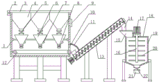
Fig. 1 is a schematic structural diagram of the present invention.
Reference numbers in the figures: 1 is the feeding case, 2 is the pivot, 3 is sealed lid, 4 is the storage hopper, 5 is first solenoid valve, 6 is the weighing hopper, 7 is weighing sensor, 8 is the second solenoid valve, 9 is the controller, 10 is the discharge gate, 11 is the arc dust cover, 12 is the conveyer belt, 13 is screw conveyer, 14 is the unloading pipe, 15 is the feeder hopper, 16 is the (mixing) shaft, 17 is stirring driving motor, 18 is mixing mixer, 19 is the agitator housing, 20 is the stirring rake, 21 is the discharging pipe, 22 is the third solenoid valve.
Detailed Description
The present invention will be described in further detail with reference to the accompanying drawings and specific embodiments:
as shown in FIG. 1, a refractory production raw material feeding apparatus comprises a feeding box 1 serving as a main container for quantitatively proportioning and discharging raw materials. The upper portion in the feeding case 1 is equipped with a plurality of storage hoppers 4 for keep in each refractory's raw materials for production respectively, so that realize quantitative ratio. The specific number of storage hoppers 4 is determined by the number of types of material required. All be equipped with weighing hopper 6 below storage hopper 4 for carry out quantitative weighing to each raw materials, the cooperation realizes the quantitative ratio of raw materials. The bottom outlets of the storage hoppers 4 are connected with the top inlets of the weighing hoppers 6 through first electromagnetic valves 5, weighing sensors 7 are arranged on the outer walls of the bottoms of the weighing hoppers 6, second electromagnetic valves 8 are arranged on the bottom outlets of the weighing hoppers 6, a controller 9 is arranged on the outer wall of the feeding box 1, the weighing sensors 7, the first electromagnetic valves 5 and the second electromagnetic valves 8 are electrically connected with the controller 9, so that when the weighing hopper is used, the first electromagnetic valves 5 can be opened through the controller 9 firstly, each production raw material falls into the corresponding weighing hoppers 6 from the storage hoppers 4, the weighing sensors 7 on the weighing hoppers 6 start to work, the weight signals of the weighing hoppers 6 can be transmitted to the controller 9, the controller 9 receives the signals and compares the signals with the weight set values corresponding to the raw materials, when the weight of each raw material reaches the respective set value, the controller 9 can automatically control the first electromagnetic valves 5 corresponding to each raw material and open the corresponding second electromagnetic valves 8, the raw materials which are proportioned can be discharged quantitatively, automatic quantitative and accurate proportioning of the raw materials is realized, problems of proportioning errors, high labor intensity and the like during manual feeding are avoided, and the improvement of feeding efficiency and the quality of finished products of refractory materials are facilitated. The controller 9 can be a conventional PLC controller on the market. The conveyer belt 12 is horizontally arranged below the weighing hopper 6, the side wall of the feeding box 1 corresponding to the tail end of the conveyer belt 12 is provided with a discharge port 10, and the tail end of the conveyer belt 12 extends out of the discharge port 10, so that the quantitatively-prepared raw materials can fall onto the conveyer belt 12, are driven by the conveyer belt 12 to advance and finally discharge from the feeding box 1 through the discharge port 10, and the raw materials are conveniently conveyed and fed subsequently.
In this embodiment, a screw conveyor 13 is provided at the rear end of the conveyor belt 12, inclined upwards away from the feed box 1, for the lifting conveyance of the material. The bottom inlet of the screw conveyor 13 corresponds to the tail end of the conveyor belt 12, and is used for matching with the conveyor belt 12, so that the proportioned raw materials enter the screw conveyor 13 to be lifted and transported. A mixer 18 is provided below the top outlet of the screw conveyor 13 to mix and stir the raw materials. A hopper 15 is provided at the top end of the mixer 18 for feeding. The top of the feed hopper 15 is sealed, and the top outlet of the screw conveyor 13 is communicated with the top of the feed hopper 15 through the discharge pipe 14, so that the feeding and stirring processes of the mixing stirrer 18 are in a relatively sealed environment, and the dust pollution is reduced. The raw materials that the ratio is good pass through conveyer belt 12 and go out the material jointly, share a screw conveyer 13 again and directly promote to carry and stir in mixing mixer 18, but the equipment quantity that significantly reduces the use and the maintenance cost of equipment, is favorable to the economic benefits of enterprise.
In this embodiment, the top of feeding case 1 is equipped with sealed lid 3 for seal feeding case 1, produce the dust and harm surrounding environment and health on the one hand when can preventing the unloading, on the other hand can avoid the raw materials to keep in storage hopper 4 with the contact of outside air, moisture is to being the influence of likepowder raw materials for production in the reduction outside air, reduces the raw materials caking rate, is favorable to subsequent processing production. One end of the sealing cover 3 is rotatably connected with the top of the feeding box 1 through the rotating shaft 2 arranged on one side of the feeding box 1, so that the feeding box 1 can be opened and closed conveniently, and the raw materials can not enter the sealing cover. The bottom import top of screw conveyer 13 is equipped with arc dust cover 11, and the one end fixed connection of arc dust cover 11 is on the lateral wall of the feeding case 1 of discharge gate 10 top, and other end fixed connection is on screw conveyer 13's shell body for produced dust when getting into screw conveyer 13 blocks the raw materials that the ratio is good, prevents that the dust from loosing outward and influencing surrounding environment and staff. Through the cooperation of the sealing cover 3, the dust cover 11 and the sealed feed hopper 15, the quantitative proportioning, blanking, feeding and mixing of raw materials are all in a relatively sealed environment, the harm of dust to the surrounding environment and the human health can be avoided, and the health of workers is guaranteed.
In this embodiment, the mixing agitator 18 includes an agitator housing 19, and a mixer shaft 16 is vertically and rotatably disposed in the agitator housing 19, the top end of the mixer shaft 16 penetrates through the top of the agitator housing 19 and is fixedly connected with the output end of an agitator driving motor 17 disposed at the top of the agitator housing 19, a plurality of paddles 20 are disposed on the outer wall of the mixer shaft 16, and power is provided through the agitator driving motor 17 to drive the mixer shaft 16 and the paddles 20 to rotate, thereby realizing mixing and agitating the raw materials. The stirring paddles 20 are uniformly distributed at intervals from top to bottom so as to ensure uniform and complete stirring and improve the stirring efficiency and the stirring quality. The bottom of stirring shell 19 is equipped with discharging pipe 21, is equipped with third solenoid valve 22 on the discharging pipe 21, and third solenoid valve 22 is connected with controller 9 electricity for after raw materials misce bene, accessible controller 9 opens third solenoid valve 22, link up discharging pipe 21 and carry out the ejection of compact.
The utility model discloses a use method: the utility model discloses when using, rotate sealed lid 3 earlier, open feeding box 1, send into each raw materials for production of refractory material respectively and keep in each storage hopper 4, first solenoid valve 5 and second solenoid valve 8 all are in the closed condition this moment. And then, the controller 9 opens the first electromagnetic valve 5 to enable each production raw material to fall into the corresponding weighing hopper 6, the weighing sensors 7 on the weighing hoppers 6 start to work, and weight signals of the weighing hoppers 6 are transmitted to the controller 9. The controller 9 receives the signal and compares the signal with a weight set value corresponding to each raw material, when the weight of each raw material reaches the respective set value, the controller 9 automatically controls to close the first electromagnetic valve 5 corresponding to each raw material and open the corresponding second electromagnetic valve 8, so that each raw material can fall onto the conveyor belt 12 in a quantitative manner, is driven by the conveyor belt 12 to advance and is conveyed into the screw conveyor 13, and finally enters the mixing stirrer 18 through the feed hopper 15 after being lifted and conveyed by the screw conveyor 13 to be mixed and stirred. After the mixture is uniformly mixed and stirred, the third electromagnetic valve 22 is opened through the controller 9 to discharge the mixture.
The above description is only for the preferred embodiment of the present invention, and is not intended to limit the present invention, and any modifications, equivalent replacements, improvements, etc. made within the spirit and principle of the present invention should be included within the protection scope of the present invention.
Claims (6)
1. The utility model provides a refractory material raw materials for production feed arrangement, a serial communication port, including the feeding case, upper portion in the feeding case is equipped with a plurality of storage hoppers, the storage hopper below all is equipped with the fill of weighing, storage hopper bottom export all links to each other with the import of the top of fighting of weighing through first solenoid valve, it is equipped with weighing sensor on the outer wall of the bottom of fighting to weigh, it all is equipped with the second solenoid valve on the export of the bottom of fighting of weighing, be equipped with the controller on the feeding case outer wall, weighing sensor, first and second solenoid valve all are connected with the controller electricity, the level of the below of fighting of weighing is equipped with the conveyer belt, be equipped with the discharge gate on the feeding case lateral wall that the conveyer belt tail end corresponds, the conveyer.
2. The refractory production raw material feeding device according to claim 1, wherein a sealing cover is arranged on the top of the feeding box, and one end of the sealing cover is rotatably connected with the top of the feeding box through a rotating shaft arranged on one side of the feeding box.
3. The refractory production raw material feeding device according to claim 1, wherein a screw conveyor is arranged at the tail end of the conveyor belt and inclines upwards towards a direction far away from the feeding box, a bottom inlet of the screw conveyor corresponds to the tail end of the conveyor belt, a mixing stirrer is arranged below a top outlet of the screw conveyor, a feeding hopper is arranged at one end of the top of the mixing stirrer, the top of the feeding hopper is sealed, and the top outlet of the screw conveyor is communicated with the top of the feeding hopper through a discharging pipe.
4. The refractory production raw material feeding device according to claim 3, wherein an arc-shaped dust cover is arranged above the bottom inlet of the screw conveyor, one end of the arc-shaped dust cover is fixedly connected to the outer side wall of the feeding box above the discharge port, and the other end of the arc-shaped dust cover is fixedly connected to the outer shell of the screw conveyor.
5. The refractory production raw material feeding device according to claim 3, wherein the mixing stirrer comprises a stirring shell, a stirring shaft is vertically and rotatably arranged in the stirring shell, the top end of the stirring shaft penetrates through the top of the stirring shell and is fixedly connected with the output end of a stirring driving motor arranged at the top of the stirring shell, a plurality of stirring paddles are arranged on the outer wall of the stirring shaft, and the stirring paddles are uniformly distributed at intervals from top to bottom.
6. The refractory production feedstock feed device of claim 5, wherein the agitator housing has a discharge tube at a bottom thereof, the discharge tube having a third solenoid valve thereon, the third solenoid valve being electrically connected to the controller.
Priority Applications (1)
| Application Number | Priority Date | Filing Date | Title |
|---|---|---|---|
| CN201920617270.5U CN210286026U (en) | 2019-04-30 | 2019-04-30 | Refractory material raw materials for production feed arrangement |
Applications Claiming Priority (1)
| Application Number | Priority Date | Filing Date | Title |
|---|---|---|---|
| CN201920617270.5U CN210286026U (en) | 2019-04-30 | 2019-04-30 | Refractory material raw materials for production feed arrangement |
Publications (1)
| Publication Number | Publication Date |
|---|---|
| CN210286026U true CN210286026U (en) | 2020-04-10 |
Family
ID=70068586
Family Applications (1)
| Application Number | Title | Priority Date | Filing Date |
|---|---|---|---|
| CN201920617270.5U Expired - Fee Related CN210286026U (en) | 2019-04-30 | 2019-04-30 | Refractory material raw materials for production feed arrangement |
Country Status (1)
| Country | Link |
|---|---|
| CN (1) | CN210286026U (en) |
Cited By (3)
| Publication number | Priority date | Publication date | Assignee | Title |
|---|---|---|---|---|
| CN112938359A (en) * | 2021-02-09 | 2021-06-11 | 洲际海峡能源科技有限公司 | Proppant feeding device for oil and gas well fracturing site |
| CN114180314A (en) * | 2021-12-13 | 2022-03-15 | 湖北和诺生物工程股份有限公司 | Closed feeding system |
| CN115288114A (en) * | 2022-08-16 | 2022-11-04 | 福建南方路面机械股份有限公司 | Continuous soil improvement system |
-
2019
- 2019-04-30 CN CN201920617270.5U patent/CN210286026U/en not_active Expired - Fee Related
Cited By (4)
| Publication number | Priority date | Publication date | Assignee | Title |
|---|---|---|---|---|
| CN112938359A (en) * | 2021-02-09 | 2021-06-11 | 洲际海峡能源科技有限公司 | Proppant feeding device for oil and gas well fracturing site |
| CN114180314A (en) * | 2021-12-13 | 2022-03-15 | 湖北和诺生物工程股份有限公司 | Closed feeding system |
| CN114180314B (en) * | 2021-12-13 | 2023-10-24 | 湖北和诺生物工程股份有限公司 | Closed feeding system |
| CN115288114A (en) * | 2022-08-16 | 2022-11-04 | 福建南方路面机械股份有限公司 | Continuous soil improvement system |
Similar Documents
| Publication | Publication Date | Title |
|---|---|---|
| CN210286026U (en) | Refractory material raw materials for production feed arrangement | |
| CN210905994U (en) | Quantitative mixing device is used in powder production | |
| CN211418549U (en) | Batching system is used in refractory material production | |
| CN207174022U (en) | A kind of quantitative filling system of canning line | |
| CN209968178U (en) | Self-service feed proportioning device | |
| CN212309509U (en) | Corundum spinel castable batching device | |
| CN105922581A (en) | 3D printer with automatic raw material weighing and feeding functions | |
| CN111941657A (en) | Production device and use method of high-performance concrete premixed material | |
| CN109384182A (en) | A kind of quantitative filling system of canning line | |
| CN213833769U (en) | Feeding system of submerged arc furnace | |
| CN210726647U (en) | Automatic change fodder production line | |
| CN201227585Y (en) | Automatic feeding blender | |
| CN102514091A (en) | Closed automatic production device for refractory castable | |
| CN202379097U (en) | Castable refractory batching, uniform mixing and automatic packing device | |
| CN213408336U (en) | High-efficient anti waterproofing agent dosing unit that splits | |
| CN209834051U (en) | Stirring and filling integrated machine | |
| CN107803931A (en) | One kind stirring production line | |
| CN208494089U (en) | Proportioner for fertilizer production | |
| CN213995726U (en) | Novel high-efficient chemical fertilizer production machine | |
| CN217450020U (en) | Full-automatic color-selecting, mixing, distributing and feeding system for titanium alloy | |
| CN217093265U (en) | Protein feed proportioning system of fodder | |
| CN220176896U (en) | Liquid fertilizer production equipment | |
| CN212263112U (en) | Mixing arrangement of additive for plastics processing | |
| CN215782924U (en) | Raw materials ratio mixing arrangement is used in refractory castable production | |
| CN216005971U (en) | Vanadium nitride ball making system |
Legal Events
| Date | Code | Title | Description |
|---|---|---|---|
| GR01 | Patent grant | ||
| GR01 | Patent grant | ||
| CF01 | Termination of patent right due to non-payment of annual fee | ||
| CF01 | Termination of patent right due to non-payment of annual fee |
Granted publication date: 20200410 Termination date: 20210430 |