CN210219783U - Urban solid waste smashing and incinerating device - Google Patents
Urban solid waste smashing and incinerating device Download PDFInfo
- Publication number
- CN210219783U CN210219783U CN201921236503.3U CN201921236503U CN210219783U CN 210219783 U CN210219783 U CN 210219783U CN 201921236503 U CN201921236503 U CN 201921236503U CN 210219783 U CN210219783 U CN 210219783U
- Authority
- CN
- China
- Prior art keywords
- exhaust
- jar
- gas treatment
- treatment room
- smashing
- Prior art date
- Legal status (The legal status is an assumption and is not a legal conclusion. Google has not performed a legal analysis and makes no representation as to the accuracy of the status listed.)
- Active
Links
Images

Classifications
-
- Y—GENERAL TAGGING OF NEW TECHNOLOGICAL DEVELOPMENTS; GENERAL TAGGING OF CROSS-SECTIONAL TECHNOLOGIES SPANNING OVER SEVERAL SECTIONS OF THE IPC; TECHNICAL SUBJECTS COVERED BY FORMER USPC CROSS-REFERENCE ART COLLECTIONS [XRACs] AND DIGESTS
- Y02—TECHNOLOGIES OR APPLICATIONS FOR MITIGATION OR ADAPTATION AGAINST CLIMATE CHANGE
- Y02E—REDUCTION OF GREENHOUSE GAS [GHG] EMISSIONS, RELATED TO ENERGY GENERATION, TRANSMISSION OR DISTRIBUTION
- Y02E20/00—Combustion technologies with mitigation potential
- Y02E20/12—Heat utilisation in combustion or incineration of waste
-
- Y—GENERAL TAGGING OF NEW TECHNOLOGICAL DEVELOPMENTS; GENERAL TAGGING OF CROSS-SECTIONAL TECHNOLOGIES SPANNING OVER SEVERAL SECTIONS OF THE IPC; TECHNICAL SUBJECTS COVERED BY FORMER USPC CROSS-REFERENCE ART COLLECTIONS [XRACs] AND DIGESTS
- Y02—TECHNOLOGIES OR APPLICATIONS FOR MITIGATION OR ADAPTATION AGAINST CLIMATE CHANGE
- Y02E—REDUCTION OF GREENHOUSE GAS [GHG] EMISSIONS, RELATED TO ENERGY GENERATION, TRANSMISSION OR DISTRIBUTION
- Y02E20/00—Combustion technologies with mitigation potential
- Y02E20/30—Technologies for a more efficient combustion or heat usage
Landscapes
- Processing Of Solid Wastes (AREA)
Abstract
The utility model discloses a municipal solid waste crushing and burning device, including smashing the jar, burning tower body and exhaust-gas purification case, conveyer and the feed end fixed connection who burns tower body one side are passed through to one side bottom of smashing the jar, the top one side fixed connection that the top discharge port that burns the tower body passes through blast pipe and exhaust-gas purification case, the surface cladding of blast pipe has first heat transfer coil, and exhaust-gas purification case's inside separates into electricity generation room and exhaust-gas treatment room through the baffle, one side swing joint of smashing the jar has the pull board, and the tip fixed mounting of pull board has the magnet body. The device structural design is simple reasonable, and convenient operation is convenient for smash recovery waste metal to rubbish, and the effectual processing of preheating in to the kibbling waste gas of rubbish and the waste gas is retrieved simultaneously, reduces the energy effect, improves and burns efficiency.
Description
Technical Field
The utility model belongs to the technical field of municipal administration, concretely relates to municipal solid waste smashes and burns device.
Background
Along with the development of society, the urbanization rate is also higher and higher, and the rubbish that people who live in the city just also more and more, and these rubbish directly burn on the one hand combustion efficiency is low, consumes a large amount of energy, has some metal object that can retrieve and recycle in the rubbish on the other hand, directly burns relatively extravagantly, and metal object also does not burn well, and the environmental pollution is caused to the direct emission of waste gas to current waste incineration device simultaneously easily, and preheating in the waste gas directly discharges and also causes the energy waste.
SUMMERY OF THE UTILITY MODEL
An object of the utility model is to provide an urban solid waste smashes and burns device is convenient for smash recovery waste metal to rubbish, and the effectual processing of preheating in to the kibbling waste gas of rubbish and waste gas is retrieved simultaneously, reduces the energy effect, improves and burns efficiency, safety and stability.
In order to achieve the above object, the utility model provides a following technical scheme: the utility model provides an urban solid waste smashes burns device, is including smashing jar, burning tower body and exhaust-gas purification case, one side bottom of smashing the jar is passed through conveyer and is burned the feed end fixed connection of tower body one side, the top exhaust port that burns the tower body passes through top one side fixed connection of blast pipe and exhaust-gas purification case, the surface cladding of blast pipe has first heat exchange coil, and exhaust-gas purification case's inside separates into electricity generation room and exhaust-gas treatment room through the baffle, the welding of top one side of exhaust-gas treatment room has the outlet duct, one side swing joint of smashing the jar has the pull board, and the tip fixed mounting of pull board has the magnet body.
Preferably, the top welding of smashing the jar has the feeder hopper, and the bottom of smashing the jar is equipped with and is used for waste water exhaust blow off pipe, the inside top of smashing the jar has two sets of crushing rollers through antifriction bearing fixed mounting, and the positive fixed mounting of smashing the jar has the inverter motor who is connected with the transmission of crushing roller.
Preferably, conveyer includes the pay-off shell, and the inside fixed mounting of pay-off shell has the conveyer belt body, the outside one end fixed mounting of pay-off shell has the step motor who is connected with the transmission of conveyer belt body, and the conveyer belt body is including setting up the horizontal transfer area and the slope conveyer belt of setting in the pay-off shell in the inside bottom of jar of smashing, the surface paste of conveyer belt body has the non-skid protrusions.
Preferably, the back top of electricity generation room is equipped with the pipeline with blast pipe fixed connection, and installs on one side of the inside of pipeline and take turns the body, the bottom of pipeline runs through baffle fixedly connected with connecting pipe, and the vertical setting of connecting pipe is in exhaust-gas treatment room, the inside bottom of electricity generation room is through spring damper fixedly connected with layer board, and top one side fixed mounting of layer board has the gearbox body, the input shaft of gearbox body is passed through belt pulley transmission with the pivot of taking turns the body and is connected, and the generator body who is connected with gearbox body transmission is still installed at the top of layer board.
Preferably, the top fixed mounting of exhaust-gas treatment room has just the motor that just reverses, and just the output shaft of just reversing the motor stretches into the transmission in the exhaust-gas treatment room and is connected with paddle agitator body, the inside top of exhaust-gas treatment room is inlayed and is had ultraviolet lamp, and the inside bottom fixed mounting of exhaust-gas treatment room has second heat exchange coil, the positive from the top down of exhaust-gas treatment room has feed liquor pipe and the drain pipe of taking the rubber buffer in proper order to weld.
Preferably, the connection part of the first heat exchange coil and the exhaust pipe is embedded with a heat conducting fin, and the lower end of the exhaust gas treatment chamber, which is positioned at the exhaust pipe, is provided with a filter bag filled with activated carbon.
Compared with the prior art, the beneficial effects of the utility model are that: the utility model discloses a crushing roller in frequency conversion motor area in the crushing tank can carry out effectual smashing to rubbish, utilizes the magnet body of pull board tip to retrieve metal waste and adsorb when rubbish after smashing falls on the conveyer belt body, and then this internal incineration disposal of tower is sent to burning to rubbish after smashing to the conveyer belt body that step motor drove for msw incineration efficiency.
In addition, when flue gas with high temperature generated in the process of waste incineration enters the waste gas purification box through the exhaust pipe, heat in the flue gas is replaced by the first heat exchange coil pipe and recycled, then the flue gas enters the pipeline to drive the turbine body to rotate, so that the gearbox body is rotated and the rotating speed is changed under the action of the belt pulley, and finally the generator body works to generate electric power.
In addition, the flue gas gets into the reaction solution in the exhaust-gas treatment room through the connecting pipe in to remove dust and take place neutralization and replacement reaction with reaction solution, the paddle agitator body that drives through positive reverse motor can stir the exhaust-gas treatment solution in the exhaust-gas treatment room, the efficiency of carrying out neutralization and replacement reaction to harmful substance in the waste gas is improved, and ultraviolet lamp can carry out the disinfection operation of disinfecting to the gas after the reaction, utilize second heat exchange coil pipe can carry out further replacement and retrieve after letting in reaction solution to flue gas residual heat, the filter bag of filling active carbon can carry out further absorption harmful substance and moisture absorption operation to the waste gas after handling, guarantee that tail gas emission quality is up to standard.
Drawings
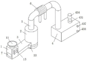
Fig. 1 is a schematic structural view of the present invention;
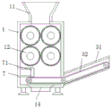
FIG. 2 is a cross-sectional view of the crushing tank of the present invention;
fig. 3 is a sectional view of the exhaust gas purifying box of the present invention.
In the figure: 1 crushing tank, 11 feed hoppers, 12 crushing rollers, 13 variable frequency motors, 14 sewage pipes, 2 incineration tower bodies, 3 conveying devices, 31 feeding shells, 32 conveying belt bodies, 33 stepping motors, 4 waste gas purification boxes, 41 partition plates, 42 power generation chambers, 421 pipelines, 422 turbine bodies, 423 connecting pipes, 424 spring shock absorbers, 425 support plates, 426 generator bodies, 427 gearbox bodies, 428 belt pulleys, 43 waste gas treatment chambers, 431 forward and reverse rotating motors, 432 paddle type stirrer bodies, 433 ultraviolet lamps, gas outlet pipes 434, 435 filter bags, 436 second heat exchange coils, 437 liquid inlet pipes, 438 liquid outlet pipes, 5 exhaust pipes, 6 first heat exchange coils, 7 drawing plates and 71 magnet bodies.
Detailed Description
The technical solutions in the embodiments of the present invention will be described clearly and completely with reference to the accompanying drawings in the embodiments of the present invention, and it is obvious that the described embodiments are only some embodiments of the present invention, not all embodiments. Based on the embodiments in the present invention, all other embodiments obtained by a person skilled in the art without creative work belong to the protection scope of the present invention.
The utility model provides a municipal solid waste crushing and burning device as shown in figures 1-3, including smashing jar 1, burning tower body 2 and exhaust-gas purification case 4, conveyer 3 is passed through to one side bottom of smashing jar 1 and the feed end fixed connection who burns tower body 2 one side, the top exhaust port that burns tower body 2 passes through blast pipe 5 and exhaust-gas purification case 4's top one side fixed connection, the surface cladding of blast pipe 5 has first heat transfer coil 6, and exhaust-gas purification case 4's inside separates into electricity generation room 42 and exhaust-gas treatment room 43 through baffle 41, the welding of top one side of exhaust-gas treatment room 43 has outlet duct 434, one side swing joint who smashes jar 1 has pull board 7, and pull board 7's end fixing installs magnet body 71.
Specifically, the top welding of smashing jar 1 has feeder hopper 11, and the bottom of smashing jar 1 is equipped with and is used for waste water exhaust's blow off pipe 14, there are two sets of crushing rollers 12 on the inside top of smashing jar 1 through antifriction bearing fixed mounting, and every group crushing roller 12 has two of intermeshing, and the positive fixed mounting of smashing jar 1 has inverter motor 13 of being connected with the transmission of crushing roller 12. Waste liquid in the rubbish can be effectively discharged through the waste water discharge sewage discharge pipe 14 and is treated, and the waste can be effectively smashed by the multiple groups of smashing rollers 12 driven by the variable frequency motor 13, so that the smashing efficiency and the smashing quality are improved.
Preferably, conveyer 3 includes pay-off shell 31, and the inside fixed mounting of pay-off shell 31 has conveyer belt body 32, the outside one end fixed mounting of pay-off shell 31 has step motor 33 of being connected with the transmission of conveyer belt body 32, and conveyer belt body 32 is including setting up the horizontal transfer area and the slope conveyer belt of setting in pay-off shell 31 in the inside bottom of jar 1 that smashes, the surface paste of conveyer belt body 32 has the non-slip raised. The horizontal conveyor belt that sets up in the inside bottom of crushing jar 1 through step motor 33 and the conveyer belt body 32 that the slope conveyer belt of setting in pay-off shell 31 is constituteed can effectually carry the rubbish after smashing to burn burning tower body 2, and the surface paste of conveyer belt body 32 has the non-skid raised can improve the stability to rubbish conveying.
Preferably, the top end of the back of the power generation chamber 42 is provided with a pipeline 421 fixedly connected with the exhaust pipe 5, a turbine body 422 is installed on one side of the inside of the pipeline 421, the bottom end of the pipeline 421 penetrates through the partition plate 41 and is fixedly connected with a connecting pipe 423, the connecting pipe 423 is vertically arranged in the exhaust gas treatment chamber 43, the bottom end of the inside of the power generation chamber 42 is fixedly connected with a supporting plate 425 through a spring damper 424, a gearbox body 427 is fixedly installed on one side of the top of the supporting plate 425, an input shaft of the gearbox body 427 is in transmission connection with a rotating shaft of the turbine body 422 through a belt pulley 428, and a generator body 426 in transmission connection with the gearbox body 427 is further installed on the. Can rotate when the flue gas passes through the turbine body 422 in the pipeline 421, thereby realize gearbox body 427 rotation and change the rotational speed under the belt pulley 428 effect, make the work of generator body 426 at last produce electric power, the effectual cushioning effect that plays of layer board 425 at spring damper 424 top when supporting fixed gearbox body 427 and generator body 426, and vertical setting can be guaranteed in the reaction solution that the flue gas got into in the exhaust-gas treatment room 43 at the connecting pipe 423 of exhaust-gas treatment room 43, thereby realize the dust removal of flue gas and take place the neutralization and the replacement reaction.
Preferably, exhaust-gas treatment room 43's top fixed mounting has just reversing motor 431, and just reversing motor 431's output shaft stretches into in exhaust-gas treatment room 43 transmission and is connected with paddle agitator body 432, ultraviolet lamp 433 is inlayed on the inside top of exhaust-gas treatment room 43, and exhaust-gas treatment room 43's inside bottom fixed mounting has second heat transfer coil 436, exhaust-gas treatment room 43 openly from the top down has welded feed liquor pipe 437 and drain pipe 438 of taking the rubber buffer in proper order. Paddle agitator body 432 through positive reverse motor 431 drive can stir the exhaust-gas treatment solution in exhaust-gas treatment room 43, the improvement carries out the efficiency of neutralization displacement reaction to harmful substance in the waste gas, and ultraviolet lamp 433 can carry out the disinfection operation of disinfecting to the gas after the reaction, utilize second heat exchange coil 436 to carry out further replacement and retrieve after the residual heat of flue gas lets in reaction solution, take the reaction solution after the reaction in new reaction solution and the exhaust-gas treatment room 43 of adding in the exhaust-gas treatment room 43 of rubber buffer and drain pipe 438 can be convenient for.
Preferably, a heat conducting fin is embedded at the connection position of the first heat exchange coil 6 and the exhaust pipe 5, and a filter bag 435 filled with activated carbon is installed inside the exhaust gas treatment chamber 43 at the lower end of the exhaust pipe 434. Can improve the heat exchange efficiency and the heat transfer effect of first heat exchange coil 6 to flue gas in the blast pipe 5 through the conducting strip, and the filter bag 435 of filling the active carbon can carry out further absorption harmful substance and moisture absorption operation to the waste gas after handling, guarantees that exhaust emission quality is up to standard.
The electrical components presented in the document are electrically connected with an external master controller and 220V mains, and the master controller can be a conventional known device for controlling a computer and the like.
The working principle is as follows: when the garbage incinerator is used, firstly, household garbage is poured into the crushing tank 1 from the feeding hopper 11, the garbage can be effectively crushed through the crushing roller 12 arranged on the variable frequency motor 13 in the crushing tank 1, the crushed garbage can fall onto the conveyor belt body 32 by utilizing the magnet body 71 arranged at the end part of the pull plate 7, and meanwhile, metal waste, particularly common iron products, can be recycled and adsorbed, then the crushed garbage is conveyed into the incineration tower body 2 by the conveyor belt body 32 driven by the stepping motor 33 for incineration treatment, when high-temperature flue gas generated in garbage incineration enters the waste gas purification box 4 through the exhaust pipe 5, heat in the flue gas is replaced by the first heat exchange coil 6 for recycling, then the flue gas enters the pipeline 421 to drive the turbine body 427 to rotate, so that the gearbox body rotates under the action of the belt pulley 428 and the rotating speed is changed, and finally the generator body 426 works to generate electric power, then the flue gas enters the reaction solution in the waste gas treatment chamber 43 through the connecting pipe 423 for dedusting and neutralization and replacement reaction with the reaction solution, the paddle type stirrer body 432 driven by the forward and reverse rotating motor 431 can stir the waste gas treatment solution in the waste gas treatment chamber 43, the efficiency of neutralization and replacement reaction on harmful substances in the waste gas is improved, the ultraviolet lamp 433 can perform sterilization and disinfection operation on the reacted gas, the second heat exchange coil 436 can be used for introducing the residual heat of the flue gas into the reaction solution for further replacement and recovery, the filter bag 435 filled with active carbon can perform further harmful substance adsorption and moisture absorption operation on the treated waste gas, the emission quality of the tail gas is ensured to reach the standard, and the finally treated flue gas is discharged from the gas outlet pipe 434, the device has simple and reasonable structural design and convenient operation, and is convenient for crushing and recovering waste metals from garbage, simultaneously, the waste gas and the waste gas after garbage crushing are effectively treated and recycled, the energy effect is reduced, the incineration efficiency is improved, the safety and the stability are realized, the application range is wide, and the popularization is facilitated.
Finally, it should be noted that: although the present invention has been described in detail with reference to the foregoing embodiments, it will be apparent to those skilled in the art that modifications and variations can be made in the embodiments or in part of the technical features of the embodiments without departing from the spirit and the scope of the invention.
Claims (6)
1. The utility model provides an urban solid waste smashes incineration device, includes crushing jar, burns tower body and exhaust-gas purification case, its characterized in that: smash one side bottom of jar and burn the feed end fixed connection of tower body one side through conveyer, the top one side fixed connection of top that the top exhaust port of burning the tower body passes through blast pipe and exhaust-gas purification case, the surface cladding of blast pipe has first heat transfer coil pipe, and exhaust-gas purification case's inside separates into electricity generation room and exhaust-gas treatment room through the baffle, the welding of exhaust-gas treatment room's top one side has the outlet duct, one side swing joint of smashing the jar has the pull board, and the tip fixed mounting of pull board has the magnet body.
2. The municipal solid waste crushing and incinerating device according to claim 1, wherein: the top welding of smashing the jar has the feeder hopper, and the bottom of smashing the jar is equipped with and is used for waste water exhaust blow off pipe, there are two sets of crushing rollers on the inside top of smashing the jar through antifriction bearing fixed mounting, and the positive fixed mounting who smashes the jar has the inverter motor who is connected with the transmission of crushing roller.
3. The municipal solid waste crushing and incinerating device according to claim 2, wherein: conveyer includes the pay-off shell, and the inside fixed mounting of pay-off shell has the conveyer belt body, the outside one end fixed mounting of pay-off shell has the step motor who is connected with the transmission of conveyer belt body, and the conveyer belt body is including setting up the horizontal transfer area and the slope conveyer belt of setting in the pay-off shell in crushing jar inside bottom, the surface paste of conveyer belt body has the non-skid raised.
4. The municipal solid waste crushing and incinerating device according to claim 3, wherein: the back top of electricity generation room is equipped with the pipeline with blast pipe fixed connection, and installs on one side of the inside of pipeline and take turns the body, the bottom of pipeline runs through baffle fixedly connected with connecting pipe, and the vertical setting of connecting pipe is in exhaust-gas treatment room, spring damper fixedly connected with layer board is passed through to the inside bottom of electricity generation room, and top one side fixed mounting of layer board has the gearbox body, the input shaft of gearbox body passes through belt pulley drive with the pivot of taking turns the body to be connected, and the generator body of being connected with gearbox body transmission is still installed at the top of layer board.
5. The municipal solid waste crushing and incinerating device according to claim 4, wherein: the top fixed mounting of exhaust-gas treatment room has just the motor that just reverses, and just the output shaft of just reversing the motor stretches into the transmission in the exhaust-gas treatment room and is connected with paddle agitator body, the inside top of exhaust-gas treatment room is inlayed and is had ultraviolet lamp, and the inside bottom fixed mounting of exhaust-gas treatment room has second heat exchange coil, the positive from the top down of exhaust-gas treatment room has feed liquor pipe and the drain pipe of taking the rubber buffer in proper order to weld.
6. The municipal solid waste crushing and incinerating device according to claim 5, wherein: the junction of first heat exchange coil and blast pipe is inlayed and is had the conducting strip, and the inside of exhaust-gas treatment room is located the lower extreme of outlet duct and installs the filter bag of packing active carbon.
Priority Applications (1)
| Application Number | Priority Date | Filing Date | Title |
|---|---|---|---|
| CN201921236503.3U CN210219783U (en) | 2019-08-01 | 2019-08-01 | Urban solid waste smashing and incinerating device |
Applications Claiming Priority (1)
| Application Number | Priority Date | Filing Date | Title |
|---|---|---|---|
| CN201921236503.3U CN210219783U (en) | 2019-08-01 | 2019-08-01 | Urban solid waste smashing and incinerating device |
Publications (1)
| Publication Number | Publication Date |
|---|---|
| CN210219783U true CN210219783U (en) | 2020-03-31 |
Family
ID=69919190
Family Applications (1)
| Application Number | Title | Priority Date | Filing Date |
|---|---|---|---|
| CN201921236503.3U Active CN210219783U (en) | 2019-08-01 | 2019-08-01 | Urban solid waste smashing and incinerating device |
Country Status (1)
| Country | Link |
|---|---|
| CN (1) | CN210219783U (en) |
Cited By (2)
| Publication number | Priority date | Publication date | Assignee | Title |
|---|---|---|---|---|
| CN111450961A (en) * | 2020-04-23 | 2020-07-28 | 张书香 | Garbage crushing and power generation integrated system |
| CN111594849A (en) * | 2020-06-03 | 2020-08-28 | 那玉金 | High-efficient incineration equipment of msw incineration processing |
-
2019
- 2019-08-01 CN CN201921236503.3U patent/CN210219783U/en active Active
Cited By (2)
| Publication number | Priority date | Publication date | Assignee | Title |
|---|---|---|---|---|
| CN111450961A (en) * | 2020-04-23 | 2020-07-28 | 张书香 | Garbage crushing and power generation integrated system |
| CN111594849A (en) * | 2020-06-03 | 2020-08-28 | 那玉金 | High-efficient incineration equipment of msw incineration processing |
Similar Documents
| Publication | Publication Date | Title |
|---|---|---|
| CN107388253A (en) | The consumer waste incineration device and its application method of a kind of environmentally friendly Anti-blockage | |
| CN210219783U (en) | Urban solid waste smashing and incinerating device | |
| CN104128349B (en) | The equipment that a kind of house refuse produces fuel oil, combustion gas or/and fuel gas generation | |
| CN105523699A (en) | Sludge drying and carbonizing device and technology | |
| CN212006536U (en) | Turnover type drying device based on household garbage treatment | |
| CN205664386U (en) | Incinerator for refuse treatment | |
| CN205619341U (en) | Environment -friendly refuse treatment burns burning furnace convenient to wash | |
| CN108689579A (en) | A kind of continuous compound catenary mud drying device | |
| CN109012975A (en) | A kind of environment-friendly garbage improvement reuse means convenient for discharge | |
| CN104819474B (en) | Efficient smoke-free carbonization device | |
| CN213207856U (en) | Harmless incinerator for garbage treatment | |
| CN204648265U (en) | High effective smokeless gas carbon gasifying device | |
| CN108534143A (en) | A kind of safe and efficient Environmental-protection garbage controlling device | |
| CN213202800U (en) | Sludge drying and carbonizing device | |
| CN108861214B (en) | Residential area smokeless garbage can for treating garbage by using electric energy | |
| CN210345469U (en) | Energy-saving floater treatment device | |
| CN113354247A (en) | Sludge coupling efficient power generation device | |
| CN209797735U (en) | Municipal sludge pyrolysis treatment device | |
| CN112625703A (en) | Environment-friendly biomass gasification stove | |
| CN108126972B (en) | Integrated crushing treatment device for kitchen waste | |
| CN111928258A (en) | Environment-friendly energy-saving equipment with purification device and purification method | |
| CN209291157U (en) | Conveying device is used in a kind of burning of transport of refuse | |
| CN216716229U (en) | Built-in steam pipe type waste heat utilization device for garbage treatment | |
| CN211600731U (en) | Garbage incineration equipment for environmental protection | |
| CN110566975A (en) | Sludge combustion system of waste incineration power plant |
Legal Events
| Date | Code | Title | Description |
|---|---|---|---|
| GR01 | Patent grant | ||
| GR01 | Patent grant |