Eel and loach belly dissecting and boning device
Technical Field
The utility model relates to a eel loach cuts open tripe and removes bone device belongs to eel loach processing equipment technical field.
Background
Eel and loach are taken as one of daily delicacies of dining tables, and are deeply favored by people due to the characteristics of rich nutritive value and delicious taste. In order to meet the taste of people, various food processing enterprises take eel and loach as basic raw materials, carry out industrial deep processing on the basic raw materials, and research and develop various types of instant food. In the industrial processing process of the eels and the loaches, the eels and the loaches need to be subjected to a plurality of steps of belly cutting, bone picking, cleaning and the like. At present, various devices have been developed in the market, which can mechanically complete the eel belly cutting work, but the bone removing work of eels and loaches still needs to be manually completed, so that the problems of high labor intensity and low working efficiency exist, and the production and use requirements of enterprises cannot be met; therefore, there is a need to develop a device for cutting open the belly and removing bones, which can mechanically complete the operations of cutting open the belly and removing bones of eels and loaches, so as to solve the problems existing in the prior artificial bone removal.
Disclosure of Invention
The utility model aims to provide a: the structure is compact and the design is ingenious; the eel and loach belly cutting and bone removing device solves the problems of high labor intensity and low working efficiency in the existing eel and loach belly cutting and bone removing processing.
The technical scheme of the utility model is that:
an eel and loach belly cutting and boning device comprises a frame, an extrusion conveying chain, a guide bottom plate, a boning disc cutter, a boning motor and a belly cutting device; the method is characterized in that: a guide bottom plate is fixedly arranged on the rack in an inclined manner; an extrusion conveying chain is arranged above the guide bottom plate through a driving roller and a driven roller; the extrusion conveying chain is arranged in parallel with the guide bottom plate; one end of the driving roller is connected with a conveying motor arranged on the rack through a transmission belt; two sides of the extrusion conveying chain are symmetrically and obliquely provided with two sets of deboning disc cutters through deboning motors; the deboning circular knife is positioned below the guide bottom plate; the boning disc cutters penetrate through the guide bottom plate and form a V-shaped structure with the adjacent boning disc cutters; and a belly cutting device is arranged on the rack at one end of the extrusion conveying chain.
The belly cutting device consists of a guide pipe, an extrusion conveying toothed disc, a toothed disc motor, a belly cutting motor and a belly cutting knife; two groups of sliding seats are symmetrically and slidably arranged on the rack through transverse sliding rails; the sliding seat is provided with an extrusion conveying chain wheel through a chain wheel motor; the chain wheel motors are connected with each other through an elastic pull rope; a guide pipe is fixedly arranged between the extrusion conveying crankshafts; one end of the guide pipe is connected with the guide bottom plate through the horizontal guide plate; a flattening block is fixedly arranged on the horizontal guide plate; a part of the extrusion conveying chain wheel extends to the interior of the guide pipe through the guide pipe; a belly cutting knife is arranged on the machine frame below the guide tube through a belly cutting motor; the upper part of the belly cutting knife passes through the guide tube and then extends into the guide tube; the dissecting tripe knife extending to the inner part of the guide pipe is positioned between the extrusion conveying crankshafts.
The flattening block is in a nose wing shape.
The extrusion conveying chain consists of a chain body and an extrusion block; a plurality of extrusion blocks are uniformly and fixedly arranged on the chain body; the extrusion block is an integrated structure made of plastic products; the outer surface of the extrusion block is provided with an extrusion groove with a V-shaped section.
The utility model has the advantages that:
this eel loach dissects tripe and removes bone device compact structure, design benefit can carry out the operation of dissecting the tripe of eel loach, removing the bone in succession mechanization, has solved current eel, loach and dissects the problem that intensity of labour who has in the tripe, the processing of removing the bone is big and work efficiency is low from this, has satisfied the needs of enterprise plant use.
Drawings
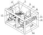
Fig. 1 is a schematic view of an axial measurement structure of the present invention;
fig. 2 is a schematic view of the structure of the present invention;
fig. 3 is a schematic top view of the present invention;
FIG. 4 is a schematic view of the structure of FIG. 3 in the direction A-A;
FIG. 5 is a schematic view of the structure in the direction B-B in FIG. 3;
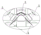
FIG. 6 is an enlarged view of the structure at C in FIG. 5;
FIG. 7 is a schematic structural view of the extrusion conveying chain and the extrusion block of the present invention;
fig. 8 is an enlarged schematic view of the structure at D in fig. 2.
In the figure: 1. the automatic bone removing machine comprises a rack, 2, an extrusion conveying chain, 3, a guide bottom plate, 4, a bone removing disc cutter, 5, a bone removing motor, 6, a bone removing device, 7, a driving roller, 8, a driven roller, 9, a chain body, 10, an extrusion block, 11, an extrusion groove, 12, a transmission belt, 13, a conveying motor, 14, a guide pipe, 15, an extrusion conveying disc, 16, a disc motor, 17, a bone removing motor, 18, a bone removing knife, 19, a transverse sliding rail, 20, a sliding seat, 21, an elastic pull rope, 22, a horizontal guide plate, 23 and a flattening block.
Detailed Description
The eel and loach belly cutting and boning device comprises a frame 1, an extrusion conveying chain 2, a guide bottom plate 3, a boning disc cutter 4, a boning motor 5 and a belly cutting device 6 (see the attached figures 1, 2 and 3 in the specification).
A guide bottom plate 3 (see the attached figure 2 in the specification) is fixedly arranged on the frame 1 in an inclined manner; an extrusion conveying chain 2 is arranged above the guide bottom plate 3 through a driving roller 7 and a driven roller 8; the extrusion conveying chain 2 and the guide bottom plate 3 are arranged in parallel; one end of the driving roller 7 is connected with a conveying motor 13 (see the attached figure 2 in the specification) arranged on the frame 1 through a driving belt 12. Therefore, when the conveying motor 13 works, the driving belt 12 and the driving roller 7 can drive the extrusion conveying chain 2 to rotate clockwise.
The extrusion conveying chain 2 is composed of a chain body 9 and an extrusion block 10 (see the description and the attached figure 7); a plurality of extrusion blocks 10 are uniformly and fixedly arranged on the chain body 9; the extrusion block 10 is a one-piece structure made of plastic. The extrusion conveyor chain 2 is mounted on the drive roller 7 and the driven roller 8 by a chain body 9.
When the eel loach that finishes dissecting the tripe passes through from direction bottom plate 3 during work like this, pivoted extrusion conveying chain 2 can be carried the eel loach through extrusion piece 10, makes it slide down along direction bottom plate 3.
The outer surface of the extrusion block 10 is provided with an extrusion groove 11 having a V-shaped cross-section. The purpose of providing the extrusion groove 11 is: firstly, the extrusion block 10 limits the eel and loach passing through the guide bottom plate 3 through the extrusion groove 11, so as to prevent the eel and loach from slipping; secondly, the extrusion block 10 can extrude and convey the eel and the loach through the V-shaped inclined plane of the extrusion groove 11, so that the eel and the loach can meet the requirement of conveying the eel and the loach with various specifications and diameters; thirdly, the extrusion groove 11 limits the eel and the loach through the V-shaped inclined surface, so that the eel and the loach move along the central line of the guide bottom plate 3 all the time, and the rotary boning cutter disc 4 achieves the purpose of accurately removing the eel and the loach spines.
Two sides of the extrusion conveying chain 2 are symmetrically and obliquely provided with two sets of deboning disc cutters 4 through a deboning motor 5; the deboning circular knife 4 is positioned below the guide bottom plate 3; the boning disc cutters 4 penetrate through the guide base plate 3 and form a V-shaped structure with the adjacent boning disc cutters 4 (see the attached figure 6 in the specification). The aim of the boning disk cutter 4 is as follows: in the process that the eel and loach slide downwards along the guide bottom plate 3 in a mode that the extrusion conveying chain 2 conveys the eel and the loach in an extrusion mode, the rotary boning disc cutter 4 can cut the spine and other parts of the eel and loach, and therefore the purpose of boning the eel and the loach is achieved.
A belly cutting device 6 is arranged on the frame 1 at one end of the extrusion conveying chain 2 (see the attached figures 1 and 2 in the specification).
The belly cutter 6 consists of a guide tube 14, an extrusion conveying chain wheel 15, a chain wheel motor 16, a belly cutting motor 17 and a belly cutting knife 18.
Two groups of sliding seats 20 are symmetrically and slidably arranged on the frame 1 through transverse sliding rails 19; the slide 20 is provided with a squeezing conveying chain wheel 15 (see the description and the attached figure 4) through a chain wheel motor 16; when the two groups of chain wheel motors 16 work, the respective extrusion conveying chain wheels 15 can be driven to rotate in opposite directions, so that the purpose of conveying the eel and the loach by the extrusion conveying chain wheels 15 in a double-roller conveying mode can be achieved.
The chain wheel motors 16 are connected with each other through an elastic pull rope 21 (see the description and the attached figure 1); under the effect of elasticity stay cord 21, have the trend of drawing close each other all the time between the chain wheel motor 16, so can ensure that different specification diameters's eel loach passes through between the extrusion conveying chain wheel 15, extrusion conveying chain wheel 15 can have certain pressure and eel loach contact, so can reach the purpose that the extrusion conveyed eel loach promptly, be unlikely to again to extrude when carrying between the chain wheel 15 pressure too big, the emergence of bad eel problem of extrusion.
A guide pipe 14 is fixedly arranged between the extrusion conveying crankshafts 15 (see the attached figure 1 in the specification); one end of the guide tube 14 is connected to the guide base plate 3 through a horizontal guide plate 22; a flattening block 23 is fixedly arranged on the horizontal guide plate 21 (see the specification and the attached figure 8);
the flattening block 23 is of a nose wing shape, so that the flattening block 23 is arranged to aim at: so that the eel loach that finishes dissecting enters into the in-process of direction bottom plate 3 through horizontal guide board 22, the exhibition piece 23 can be from the middle part extrusion completion eel loach that dissects the tripe, makes it enter into on the direction bottom plate 3 that is the state of flattening to be convenient for subsequent bone removal cutting disc 4 can be from the inside completion "bone removal" action of eel loach.
A part of the pressing feed chain wheel 15 extends through the guide tube 14 to the inside thereof; so arranged (see the description and figure 4). So that the eel and loach entering the guide pipe 14 can be smoothly output in a manner that the rotating extrusion conveying chain wheel 15 can be conveyed by extrusion.
A belly cutting knife 18 is arranged on the frame 1 below the guide pipe 14 through a belly cutting motor 17; the upper part of the belly cutting knife 18 extends into the guiding tube 14 after passing through the guiding tube; a cutting blade 18 extending into the guide tube 14 is positioned between the extrusion feed crankset 15 (see figure 4 of the specification). The purpose of so setting is: so that the rotary belly cutting knife 18 can smoothly complete the belly cutting work of the eel and the loach in the process of extruding and conveying the eel and the loach by the extruding and conveying crankset 15.
When the eel and loach belly cutting and boning device works, the conveying motor 13, the boning motor 5, the chain wheel motor 16 and the belly cutting motor 17 are started firstly; when the conveying motor 13 works, the driving belt 12 and the driving roller 7 can drive the extrusion conveying chain 2 to rotate clockwise. When the deboning motor 5 works, the deboning circular knife 4 can be driven to rotate; when the chain wheel motor 16 works, the extrusion conveying chain wheel 15 can be driven to synchronously rotate; the dissecting motor 17 can drive the dissecting knife 18 to rotate synchronously when working.
After the belly cutting and bone removing device is started, the eel and the loach to be processed are fed into the guide tube 14 in a head feeding mode; after the eel and loach to be processed enter the guide tube 14, the rotary extrusion conveying chain wheel 15 conveys the eel and loach to the horizontal guide plate 22 in an extrusion conveying mode; the rotary belly cutting knife 18 can complete the belly cutting of the eel and the loach in the process.
The eel loaches with the dissected belly enter the guide bottom plate 3 along the horizontal guide plate 22 under the conveying action of the extrusion conveying chain wheel 15, and in the process, the flattening block 23 can extrude the eel loaches with the dissected belly from the middle part to enable the eel loaches to enter the guide bottom plate 3 in a flattened state.
Subsequently, eel loaches in a flat state entering the guide bottom plate 3 slide down smoothly along the guide bottom plate 3 under the action of extrusion conveying of the rotary extrusion conveying chain 2, the spine and other parts of the eel loaches are cut by the rotary bone-picking disc cutter 4 in the process, so that the bone-removing operation is completed, the eel loaches with bones removed later output the bone-removing device for ripping the belly along the guide bottom plate 3, the eel loaches with the belly ripped and removed by the bone-removing device are all completed, and the eel loaches can enter the next working cycle.
This eel loach dissects tripe and removes bone device compact structure, design benefit can carry out the operation of dissecting the tripe of eel loach, removing the bone in succession mechanization, has solved current eel, loach and dissects the problem that intensity of labour who has in the tripe, the processing of removing the bone is big and work efficiency is low from this, has satisfied the needs of enterprise plant use.