CN210150242U - Standardized and modularized bearing and positioning device - Google Patents
Standardized and modularized bearing and positioning device Download PDFInfo
- Publication number
- CN210150242U CN210150242U CN201920906734.4U CN201920906734U CN210150242U CN 210150242 U CN210150242 U CN 210150242U CN 201920906734 U CN201920906734 U CN 201920906734U CN 210150242 U CN210150242 U CN 210150242U
- Authority
- CN
- China
- Prior art keywords
- group
- bearing
- bearing wheels
- top plate
- sliding block
- Prior art date
- Legal status (The legal status is an assumption and is not a legal conclusion. Google has not performed a legal analysis and makes no representation as to the accuracy of the status listed.)
- Active
Links
Images


Abstract
The utility model relates to a can standardize modular bear positioner for the standardized tray conveying system transfer line body module who establishes on the basis of standard aluminium alloy. The device comprises an upper top plate, a lower top plate and a guide rod supported between the upper top plate and the lower top plate, wherein one end of the upper surface of the lower top plate is provided with an integrated universal support module consisting of at least 2 component units; the other end of the upper surface of the lower top plate is provided with a driving system, and the driving system is connected with one end of the integrated universal supporting module; the core component of the jacking bearing is subjected to standardized and modularized design, so that most of the components can be universally used in certain size ranges without redesigning and manufacturing, the batch manufacturing is facilitated, the design time can be greatly shortened in the design process, the processing period can be effectively shortened when a standard module is utilized, and the manufacturing efficiency is improved; the modular design core component has higher commonality, has shortened production cycle, has reduced the design mistake risk.
Description
Technical Field
The utility model relates to a can standardize modular bear positioner is applied to the standardized tray conveying system transfer line body module of establishing on the standard aluminium alloy basis.
Background
Load bearing positioning in a production-compliant process often requires different sized designs for different workpieces. In a standardized, modular delivery system, there is a need for a rapid response to various requirements. In this condition, if the modular design is not performed, the manufacture, design and production will be subject to time and the risk of instability during the manufacture, assembly and design will be increased if the dimensions are different for each design.
In the current industry, a special design mode is mostly adopted to meet the requirement during press mounting or leakage test on a non-standard production line. In the manufacturing process, the structure is roughly divided into three types. The first is to use a wedge block mode, a cylinder is horizontally arranged to push staggered wedge blocks, so that the upper floatable wedge blocks move upwards, and inclined surface contact between the wedge blocks after moving upwards and the wedge blocks pushed by the cylinder is converted into plane contact for resisting upper pressurizing load; secondly, a horizontally arranged cylinder is used for pushing a hinge shaft in the middle of the herringbone staggered connecting rod device which deflects for 90 degrees, so that the folding form of the connecting rod is changed into the vertical form, and the self-locking property of the connecting rod device is utilized for resisting the upper pressurizing load; and thirdly, a double-cylinder design is adopted, the first cylinder is arranged perpendicular to the conveying plane and used for lifting the load tray, the second cylinder is horizontally arranged and used for pushing the solid cushion block after lifting, and the solid cushion block is supported between the upper top plate and the lower supporting seat of the load-bearing tray and used for resisting an upper pressurizing load.
The above prior art has the disadvantage that it is not possible to achieve a modular and standardized design and therefore does not solve the problem in this respect, achieving the desired effect.
Disclosure of Invention
In order to solve the technical problem, the utility model discloses a core component that technical scheme bore the jacking carries out standardization, modular design, and provides a modular positioner that bears that can standardize for most part among them can be general in some size scope, and need not redesign system.
In order to realize the purpose, the utility model discloses the technical scheme who adopts is: a bearing and positioning device capable of being standardized and modularized comprises an upper top plate, a lower top plate and a guide rod supported between the upper top plate and the lower top plate, wherein one end of the upper surface of the lower top plate is provided with an integrated universal supporting module consisting of at least 2 component units; the other end of the upper surface of the lower top plate is provided with a driving system, and the driving system is connected with one end of the integrated universal supporting module;
the 2 component units comprise 2 upper supporting blocks, 2 lower supporting blocks and 1 common sliding block wheel set;
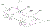
the common sliding block wheel set is of a four-wheel structure and comprises a sliding block, a first group of bearing wheels and a second group of bearing wheels which are arranged at one end of the sliding block, and a third group of bearing wheels and a fourth group of bearing wheels which are arranged at the other end of the sliding block; the position of a sliding block between the second group of bearing wheels and the third group of bearing wheels is a connecting beam part;
the connecting beam part can change the length dimension;
a group of upper supporting blocks and a group of lower supporting blocks are arranged on the sliding block parts at the positions of the first group of bearing wheels and the second group of bearing wheels in a matched manner; a group of upper supporting blocks and a group of lower supporting blocks are arranged on the sliding block parts at the positions of the third group of bearing wheels and the fourth group of bearing wheels in a matched manner;
the upper supporting block and the lower supporting block are universal parts;
the first group of bearing wheels and the third group of bearing wheels are respectively provided with 2 bearing wheels, the two groups of bearing wheels are on the same horizontal plane, and the bottoms of the wheels are lower than the bottom surface of the sliding block; the second group of bearing wheels and the fourth group of bearing wheels are respectively provided with 2 bearing wheels, the group of bearing wheels are on the same horizontal plane, and the top of each bearing wheel is higher than the top of the sliding block;
the upper supporting blocks are fixedly connected through bolts arranged on the upper top plate, the bolts are embedded in the supporting columns on the surface of the upper top plate, and the number of the supporting columns is 2; the lower support block is fixedly connected to the lower top plate through a bolt;
the upper supporting block is of a wedge block structure with an inclined surface and a reverse inclined surface, and a plane is arranged between the inclined surface and the reverse inclined surface; grooves are symmetrically formed in the upper surface of the lower support block;
the top end of the guide rod is fixedly connected to the upper top plate through a bolt, a pillar is arranged on the upper surface of the upper top plate and corresponds to the top end of the guide rod, the bolt is arranged in the pillar, a linear bearing is arranged at the bottom end of the guide rod, and the guide rod and the linear bearing are fixed on the lower top plate;
the guide rod limiting block is fixed on the cushion block through bolts, and the cushion block is fixedly connected to the lower top plate through bolts at two ends.
The driving system comprises an air cylinder, an air cylinder mounting plate is arranged between one end of a telescopic rod of the air cylinder and the air cylinder, the air cylinder and the air cylinder mounting plate are fixed through a bolt, and the bottom end of the air cylinder mounting plate is fixedly connected to the lower top plate through a bolt; the other end of the cylinder telescopic rod is a cylinder catcher;
a groove-shaped connecting structure is arranged at one end of the common sliding block wheel set, which is positioned at the sliding block position of the first group of bearing wheels; the cylinder catcher is connected in the groove-shaped connecting structure of the sliding block in a sliding manner, so that the cylinder catcher can conveniently slide up and down in the groove-shaped connecting structure;
the utility model discloses a general type of integral type supports the module and adopts the design of four-wheel structure, and the carrier block acts on the both ends of slider wheelset respectively when supporting about making, provides great lifting surface area, can support the pressure of bigger load, simultaneously, can satisfy the in service behavior of bigger tray. Up to 700mm is a standard pallet of nominal size.
For higher applicable commonality, the utility model discloses a general type of integral type supports module can carry out size change, can follow four wheels double bracing and develop into six rounds of three supports or even more, but the design is unchangeable, and the upper and lower supporting shoe is all general.
The specific working process adopting the technical scheme is as follows:
(1) the second group of bearing wheels and the fourth group of bearing wheels of the slider wheel set respectively push the upper supporting block with the inclined plane above to move upwards under the directional action of the guide rod, and simultaneously, the first group of bearing wheels and the third group of bearing wheels horizontally move on the plane of the lower supporting block; in the motion process, the sliding friction is converted into rolling friction by the bearing wheel, so that the motion resistance is reduced, and long-term maintenance is not needed;
(2) when the second group of bearing wheels and the fourth group of bearing wheels of the sliding block wheel set respectively reach the plane through the inclined planes of the upper supporting blocks, the tray for bearing and positioning reaches the highest point, and the cylinder continues to eject forwards;
(3) when the second group of bearing wheels and the fourth group of bearing wheels of the sliding block wheel set respectively pass through the plane of the upper supporting block, the second group of bearing wheels and the fourth group of bearing wheels enter a reverse inclined plane, and at the same time, the first group of bearing wheels and the third group of bearing wheels of the sliding block wheel set simultaneously enter a reverse inclined plane groove of the lower supporting plate; in the process, the upper supporting block and the sliding block wheel set fall down in the vertical direction; finally, the plane part of the upper supporting block, the plane part of the sliding block wheel set and the lower supporting block are contacted and closed; at the moment, additional pressure is added to the load tray, and the pressure is transmitted to the bottom surface of the bearing and positioning from the mutually contacted plate surfaces; this structure has the greatest supporting effect at this time.
(4) When the sliding block wheel set returns, the air cylinder pulls back the sliding block wheel set, four groups of bearing wheels of the sliding block wheel set respectively push reverse slopes of the upper supporting block and the lower supporting block, so that the effect of separating each contact surface can be achieved, and at the moment, sliding friction between steel contact surfaces can be avoided greatly in theory when the sliding block wheel set is pulled; when the cylinder rod is completely retracted, the bearing is positioned to return to the low position, and one action cycle is completed.
Compared with the prior art, the utility model uses rolling friction to replace the previous sliding friction, designs a drop point at the highest lifting position, converts the bearing contact into surface-surface contact between metal blocks instead of applying pressure on the wheel shaft, and utilizes the bearing wheels with different heights to match the inclined planes of the upper and lower supporting blocks to separate the upper and lower supporting blocks outwards when the sliding block wheel set retreats, thereby effectively avoiding the defects caused by sliding friction; and when each part leans against, can play more reliable pressure-bearing effect.
Adopt the produced beneficial effect of technical scheme of the utility model is:
the core component of the jacking bearing is subjected to standardized and modularized design, so that most of the components can be universally used in certain size ranges without redesigning and manufacturing, the batch manufacturing is facilitated, the design time can be greatly shortened in the design process, the processing period can be effectively shortened when a standard module is utilized, and the manufacturing efficiency is improved; the modular design core component has higher commonality, has shortened production cycle, has reduced the design mistake risk.
Drawings
Fig. 1 is a schematic structural diagram of the positioning device of the present invention.
Fig. 2 is an assembly view of the integrated universal support module of the positioning device of the present invention.
Fig. 3 is a perspective view of fig. 2.
Fig. 4 is a block diagram of the slider wheel set in fig. 2.
FIG. 5 is a view showing the structure of the upper supporting block of FIG. 3
Fig. 6 is a lower support block pattern of fig. 3.
Fig. 7 is a state diagram when the second group of bearing wheels and the fourth group of bearing wheels of the slider wheel set reach the upper support block bevel.
FIG. 8 is a view of the second and fourth sets of bearing wheels of the slider wheel set riding over the support block ramp to the flat surface.
FIG. 9 is a view of the second and fourth sets of bearing wheels of the slider wheel set as they pass through the plane of the support block and into the reverse slope.
In the figure, 01, bolts M8 × 25, 02, supports, 03, an upper top plate, 04, guide rods, 05, linear bearings, 06, guide rod limiting blocks, 07, bolts M8 × 20, 08, bolts M8 × 16,09, slider wheel sets, 10, a lower support block, 10-1, a lower support block groove, 11, a cylinder connector, 12, bolts M6 × 20,13, an upper support block, 14, bolts M8 × 35,15, a cylinder, 16, a mounting plate positioning pin, 19, bolts M5 × 16,20, a cylinder mounting plate, 21, a lower top plate, 09-1, a slider, 09-2, a first group of bearing wheels, 09-3, a second group of bearing wheels, 09-4, a third group of bearing wheels, 09-5, a fourth group of bearing wheels, 09-6, a groove type connecting structure, 09-a connecting beam.
Detailed Description
The present invention will be further explained with reference to the following examples and drawings, but the present invention is not limited to the following examples.
As shown in fig. 1 to 9, a standardized and modularized bearing and positioning device includes an upper top plate 03, a lower top plate 21, and a guide rod 04 supported between the upper top plate 03 and the lower top plate 21, wherein one end of the upper surface of the lower top plate 21 is provided with an integrated general type supporting module composed of at least 2 component units; the other end of the upper surface of the lower top plate 21 is provided with a driving system, and the driving system is connected with one end of the integrated universal supporting module;
the design of four wheels makes upper and lower bearing block act on the both ends of slider wheelset respectively when supporting, provides great lifting surface, can support the pressure of bigger load, simultaneously, can satisfy the in service behavior of bigger tray. Up to 700mm is a standard pallet of nominal size.
The 2 assembly units comprise 2 upper supporting blocks 13, 2 lower supporting blocks 10 and 1 common sliding block wheel set 09;
the common sliding block wheel set 09 is of a four-wheel structure and comprises a sliding block 09-1, a first group of bearing wheels 09-2 and a second group of bearing wheels 09-3 which are arranged at one end of the sliding block 09-1, and a third group of bearing wheels 09-4 and a fourth group of bearing wheels 09-5 which are arranged at the other end of the sliding block 09-1; the position of a sliding block between the second group of bearing wheels 09-3 and the third group of bearing wheels 09-4 is a part of a connecting beam 09-a;
the connecting beam 09-a part can change the length dimension;
a group of upper supporting blocks 13 and a group of lower supporting blocks 10 are arranged on the sliding block parts at the positions of the first group of bearing wheels 09-2 and the second group of bearing wheels 09-3 in a matched manner; a group of upper supporting blocks 13 and lower supporting blocks 10 are arranged on the sliding block parts at the positions of the third group of bearing wheels 09-4 and the fourth group of bearing wheels 09-5 in a matched manner;
the upper support block 13 and the lower support block 10 are universal parts;
the first group of bearing wheels and the third group of bearing wheels are respectively provided with 2 bearing wheels, the two groups of bearing wheels are on the same horizontal plane, and the bottoms of the wheels are lower than the bottom surface of the sliding block; the second group of bearing wheels and the fourth group of bearing wheels are respectively provided with 2 bearing wheels, the group of bearing wheels are on the same horizontal plane, and the top of each bearing wheel is higher than the top of the sliding block;
the upper supporting blocks 13 are fixedly connected through bolts 14 arranged on the upper top plate 03, the bolts 14 are embedded in the pillars 02 on the surface of the upper top plate, and the number of the pillars 02 is 2; the lower supporting block 10 is fixedly connected to the lower top plate 21 through a bolt 08;
the upper supporting block 13 is a wedge block structure with an inclined surface and a reverse inclined surface, and a plane is arranged between the inclined surface and the reverse inclined surface; grooves 10-1 are symmetrically formed in the upper surface of the lower support block 10;
the top end of the guide rod 04 is fixedly connected to the upper top plate 03 through a bolt 01, a support column 02 is arranged on the upper surface of the upper top plate 03 corresponding to the top end of the guide rod 04, the bolt 01 is arranged in the support column 02, a linear bearing 05 is arranged at the bottom end of the guide rod 04, and the guide rod 04 and the linear bearing 05 are fixed on the lower top plate 21;
a guide rod limiting block 06 is further arranged at a position, corresponding to the guide rod 04, of the lower surface of the lower top plate 21, a cushion block is arranged between the guide rod limiting block 06 and the lower surface of the lower top plate 21, the guide rod limiting block 06 is fixed on the cushion block through a bolt 07, and the cushion block is fixedly connected to the lower top plate 21 through bolts 19 at two ends;
the driving system comprises an air cylinder 15, an air cylinder mounting plate 20 is arranged between one end of a telescopic rod of the air cylinder 15 and the air cylinder 15, the air cylinder 15 and the air cylinder mounting plate 20 are fixed through a bolt, and the bottom end of the air cylinder mounting plate 20 is fixedly connected to a lower top plate 21 through a bolt 12; the other end of the cylinder telescopic rod is a cylinder catcher 11;
one end of the common sliding block wheel set, which is positioned at the sliding block position of the first group of bearing wheels 09-2, is provided with a groove type connecting structure 09-6; the cylinder catcher 11 is connected in a sliding manner in the groove-shaped connecting structure 09-6 of the sliding block, so that the cylinder catcher 11 can slide up and down in the groove-shaped connecting structure 09-6 conveniently;
the specific working process is as follows:
(1) the cylinder 15 transversely pushes the slider wheel set 09 moving on the lower support block 10, the second group of bearing wheels 09-3 and the fourth group of bearing wheels 09-5 of the slider wheel set 09 respectively push the upper support block 13 with the inclined surface above to move upwards under the directional action of the guide rod 04, and simultaneously, the first group of bearing wheels 09-2 and the third group of bearing wheels 09-4 horizontally move on the plane of the lower support block 10; in the motion process, the sliding friction is converted into rolling friction by the bearing wheel, so that the motion resistance is reduced, and long-term maintenance is not needed;
(2) when the second group of bearing wheels 09-3 and the fourth group of bearing wheels 09-5 of the sliding block wheel set 09 reach the plane through the inclined surfaces of the upper supporting blocks 13 respectively, the tray for bearing and positioning reaches the highest point, and the air cylinder 15 continues to eject forwards;
(3) when the second group of bearing wheels 09-3 and the fourth group of bearing wheels 09-5 of the sliding block wheel set 09 respectively pass through the plane of the upper supporting block 13, the second group of bearing wheels 09-3 and the fourth group of bearing wheels 09-5 enter a reverse inclined plane, and at the same time, the first group of bearing wheels 09-2 and the third group of bearing wheels 09-4 of the sliding block wheel set simultaneously enter a reverse inclined plane groove of the lower supporting block 10; in the process, the upper supporting block 13 and the sliding block wheel set 09 both fall in the vertical direction; finally, the plane part of the upper support block 13, the plane part of the slider wheel set 09 and the lower support block 10 are contacted and closed; at the moment, additional pressure is added to the load tray, and the pressure is transmitted to the bottom surface of the bearing and positioning from the mutually contacted plate surfaces; this structure has the greatest supporting effect at this time.
(4) When the sliding block wheel set 09 is pulled back, the air cylinder 15 pulls back the sliding block wheel set 09, four groups of bearing wheels of the sliding block wheel set 09 respectively push reverse inclined planes of the upper supporting block 13 and the lower supporting block 10, so that the effect of separating each contact surface can be achieved, and at the moment, sliding friction between steel contact surfaces can be avoided greatly in theory when the sliding block wheel set is pulled; when cylinder rod 15 is fully retracted, the load bearing position returns to the low position, completing one cycle of action.
Example two:
on the basis of the first embodiment, the slider wheel set adopts a six-wheel structure, the upper and lower supporting blocks which are universal are correspondingly matched according to the number of the bearing wheel sets, other structures are the same as the first embodiment, and the working principle is the same as the first embodiment.
On the basis of embodiment two, the slider wheelset adopts eight wheeled structures even more, and the design form is inconvenient, and upper and lower supporting shoe all can be general, all belongs to above all the utility model discloses a technical scheme's protection category.
Claims (9)
1. A can standardize modular bearing positioner which characterized in that: the device comprises an upper top plate, a lower top plate and a guide rod supported between the upper top plate and the lower top plate, wherein one end of the upper surface of the lower top plate is provided with an integrated universal supporting module consisting of at least 2 component units; and the other end of the upper surface of the lower top plate is provided with a driving system, and the driving system is connected with one end of the integrated universal supporting module.
2. A standardisable modular load-bearing locator device according to claim 1 wherein: the 2 component units include 2 upper supporting blocks, 2 lower supporting blocks and 1 common slider wheel set.
3. A standardisable modular load-bearing locator device according to claim 2 wherein: the common sliding block wheel set is of a four-wheel structure and comprises a sliding block, a first group of bearing wheels and a second group of bearing wheels which are arranged at one end of the sliding block, and a third group of bearing wheels and a fourth group of bearing wheels which are arranged at the other end of the sliding block; and the position of the sliding block between the second group of bearing wheels and the third group of bearing wheels is a connecting beam part.
4. A standardisable modular load-bearing locator device according to claim 3 wherein: the connecting beam portion may vary in length dimension.
5. A standardisable modular load-bearing positioning device according to claim 3 or 4, characterised in that: a group of upper supporting blocks and a group of lower supporting blocks are arranged on the sliding block parts at the positions of the first group of bearing wheels and the second group of bearing wheels in a matched manner; and a group of upper supporting blocks and a group of lower supporting blocks are arranged on the sliding block parts at the positions of the third group of bearing wheels and the fourth group of bearing wheels in a matched manner.
6. A standardisable modular load-bearing locator device according to claim 5 wherein: the upper supporting block and the lower supporting block are universal parts.
7. A standardisable modular load-bearing locator device according to claim 5 wherein: the first group of bearing wheels and the third group of bearing wheels are respectively provided with 2 bearing wheels, the two groups of bearing wheels are on the same horizontal plane, and the bottoms of the wheels are lower than the bottom surface of the sliding block; the second group of bearing wheels and the fourth group of bearing wheels are respectively provided with 2 bearing wheels, the bearing wheels are on the same horizontal plane, and the top of each bearing wheel is higher than the top surface of the sliding block.
8. A standardisable modular load-bearing locator device according to claim 1 wherein: the driving system comprises an air cylinder, an air cylinder mounting plate is arranged between one end of a telescopic rod of the air cylinder and the air cylinder, the air cylinder and the air cylinder mounting plate are fixed through a bolt, and the bottom end of the air cylinder mounting plate is fixedly connected to the lower top plate through a bolt; the other end of the cylinder telescopic rod is a cylinder catcher.
9. A standardisable modular load-bearing locator device according to claim 2 wherein: a groove-shaped connecting structure is arranged at one end of the common sliding block wheel set, which is positioned at the sliding block position of the first group of bearing wheels; the cylinder catcher is connected in the groove-shaped connecting structure of the sliding block in a sliding mode, and the cylinder catcher can conveniently slide up and down in the groove-shaped connecting structure.
Priority Applications (1)
| Application Number | Priority Date | Filing Date | Title |
|---|---|---|---|
| CN201920906734.4U CN210150242U (en) | 2019-06-17 | 2019-06-17 | Standardized and modularized bearing and positioning device |
Applications Claiming Priority (1)
| Application Number | Priority Date | Filing Date | Title |
|---|---|---|---|
| CN201920906734.4U CN210150242U (en) | 2019-06-17 | 2019-06-17 | Standardized and modularized bearing and positioning device |
Publications (1)
| Publication Number | Publication Date |
|---|---|
| CN210150242U true CN210150242U (en) | 2020-03-17 |
Family
ID=69763121
Family Applications (1)
| Application Number | Title | Priority Date | Filing Date |
|---|---|---|---|
| CN201920906734.4U Active CN210150242U (en) | 2019-06-17 | 2019-06-17 | Standardized and modularized bearing and positioning device |
Country Status (1)
| Country | Link |
|---|---|
| CN (1) | CN210150242U (en) |
Cited By (1)
| Publication number | Priority date | Publication date | Assignee | Title |
|---|---|---|---|---|
| CN110155695A (en) * | 2019-06-17 | 2019-08-23 | 大连德欣新技术工程有限公司 | Can standard and modular carrying positioning device |
-
2019
- 2019-06-17 CN CN201920906734.4U patent/CN210150242U/en active Active
Cited By (2)
| Publication number | Priority date | Publication date | Assignee | Title |
|---|---|---|---|---|
| CN110155695A (en) * | 2019-06-17 | 2019-08-23 | 大连德欣新技术工程有限公司 | Can standard and modular carrying positioning device |
| CN110155695B (en) * | 2019-06-17 | 2024-03-26 | 大连德欣新技术工程有限公司 | Standardized modularized bearing and positioning device |
Similar Documents
| Publication | Publication Date | Title |
|---|---|---|
| CN210150242U (en) | Standardized and modularized bearing and positioning device | |
| CN201372181Y (en) | Slim-type scissor hydraulic lifting platform | |
| CN106586527A (en) | Positioning trolley and carrying gripper matched with positioning trolley | |
| CN110155695B (en) | Standardized modularized bearing and positioning device | |
| CN210365852U (en) | Modular positioning device capable of bearing additional pressure loading | |
| CN114497858A (en) | Tray, module processing method and battery | |
| CN110155694B (en) | Modular positioning device capable of bearing additional pressure loading | |
| WO1987007870A1 (en) | Articulated-lever cutting and forming press | |
| CN115676688B (en) | Step-by-step elevating equipment | |
| CN217867940U (en) | Synchronous jacking mechanism and AGV trolley with same | |
| CN203159133U (en) | Hydraulic lifting pallet | |
| CN106428105A (en) | Traverse moving type hydraulic rerailer | |
| DE102020133542B4 (en) | Handling system and handling device for handling workpiece pallets and machine tool with handling system | |
| CN111069513B (en) | Quick die changing device and method for forging press | |
| CN110842502B (en) | Semi-automatic plate spring assembling equipment | |
| CN210456511U (en) | Novel automobile tire stopper | |
| CN102729029B (en) | Bearing press mounting device | |
| CN111842760A (en) | Movable workbench device and method for rapidly converting stress system thereof | |
| CN218965689U (en) | Full-automatic assembly device for intelligent furniture component | |
| CN207918279U (en) | The double group walking mechanism carrying toolings of crane | |
| CN212047438U (en) | Universal jig trolley for various engines of automobile | |
| CN213104257U (en) | Compression spring shaft-mounted seat device applied to spring press | |
| CN212740624U (en) | Lifting device for lifting wheel set frame | |
| CN220664741U (en) | Cargo fastening lifting device | |
| CN110978926B (en) | Multistage non-independent suspension system |
Legal Events
| Date | Code | Title | Description |
|---|---|---|---|
| GR01 | Patent grant | ||
| GR01 | Patent grant |