CN210099564U - Scrap discharge device for machine tool workbench - Google Patents
Scrap discharge device for machine tool workbench Download PDFInfo
- Publication number
- CN210099564U CN210099564U CN201920354105.5U CN201920354105U CN210099564U CN 210099564 U CN210099564 U CN 210099564U CN 201920354105 U CN201920354105 U CN 201920354105U CN 210099564 U CN210099564 U CN 210099564U
- Authority
- CN
- China
- Prior art keywords
- frame
- fixed
- groove
- plate
- chip
- Prior art date
- Legal status (The legal status is an assumption and is not a legal conclusion. Google has not performed a legal analysis and makes no representation as to the accuracy of the status listed.)
- Active
Links
Images


Abstract
The utility model discloses a lathe workstation piece eduction gear relates to machining technical field. The utility model comprises a frame, wherein the inner surface of the frame is rotationally connected with a turning plate; one end of the frame is communicated with a falling groove; the bottom end of the falling groove is communicated with a chip groove; a notch is formed on one surface of the turning plate; a first clamping plate is fixed on one end face of the turning plate; two adjacent turning plates are clamped with the notch through the first clamping plate; a second clamping plate is fixed on the inner side of the frame; the second clamping plate is clamped with one of the turning plates through the notch. The utility model discloses a plurality of side by side and the board that turns over of mutual joint, turn over the board slope when rotating the swinging boom, make the piece in proper order through hang plate, whereabouts groove and chip groove to discharge from the chip outlet through auger blade, the clastic clearance of lathe workstation of being convenient for, labour saving and time saving has reduced intensity of labour, and simple structure, easily manufacturing.
Description
Technical Field
The utility model belongs to the technical field of machining, especially, relate to a lathe workstation piece eduction gear.
Background
Machine tools are machines for manufacturing machines, also called machine tools or machine tools, which are conventionally referred to as machine tools for short. Generally, the machining method is divided into a metal cutting machine, a forging machine, a woodworking machine and the like. However, for parts with high precision requirements and fine surface roughness requirements, the final machining is generally carried out by cutting on a machine tool. The machine tool plays an important role in the construction of national economy modernization.
The conventional machine tool generally cleans the workbench by manual work when processing chips, particularly a large-scale machine tool, and workers need to enter a machine tool shield for cleaning, so that the operation is inconvenient, and the labor intensity of the workers is increased.
SUMMERY OF THE UTILITY MODEL
An object of the utility model is to provide a lathe workstation piece eduction gear has solved the artifical clearance operation of current lathe workstation surface piece problem inconvenient, that artifical intensity of labour is high.
In order to solve the technical problem, the utility model discloses a realize through following technical scheme:
the utility model relates to a scrap discharge device of a machine tool workbench, which comprises a frame, wherein a turnover plate is rotationally connected to the inner surface of the frame; one end of the frame is communicated with a falling groove; the bottom end of the falling groove is communicated with a chip groove;
a notch is formed in one surface of the turning plate; a first clamping plate is fixed on one end face of the turning plate; two adjacent turning plates are clamped with the notch through a first clamping plate;
a second clamping plate is fixed on the inner side of the frame; the second clamping plate is clamped with one of the turning plates through the notch.
Furthermore, a first fluted disc is fixed on one side surface of the turning plate; the peripheral side surface of the first fluted disc is engaged with and drives a transmission belt; a second fluted disc is meshed and driven on the inner surface of the transmission belt; one side of the second gear plate penetrates through the frame and is fixed with a rotating arm.
Furthermore, a servo motor is fixed at one end of the chip groove; one end of the servo motor rotating shaft penetrates through the chip groove and is fixed with the auger blade through the coupler.
Further, an inclined plate is fixed at the bottom of the falling groove; and a first support frame is fixed at the bottom of the inclined plate.
Furthermore, a second support frame is fixed at the bottom of the chip removal groove; the bottom of the chip groove is communicated with a chip outlet.
The utility model discloses following beneficial effect has:
the utility model discloses a plurality of side by side and the board that turns over of mutual joint, turn over the board slope when rotating the swinging boom, make the piece in proper order through hang plate, whereabouts groove and chip groove to discharge from the chip outlet through auger blade, the clastic clearance of lathe workstation of being convenient for, labour saving and time saving has reduced intensity of labour, and simple structure, easily manufacturing.
Of course, it is not necessary for any particular product to achieve all of the above-described advantages at the same time.
Drawings
In order to more clearly illustrate the technical solutions of the embodiments of the present invention, the drawings used in the description of the embodiments will be briefly introduced below, and it is obvious that the drawings in the following description are only some embodiments of the present invention, and it is obvious for those skilled in the art that other drawings can be obtained according to these drawings without creative efforts.
Fig. 1 is a schematic structural view of a scrap discharge device for a machine tool workbench according to the present invention;
FIG. 2 is a vertical cross-sectional view of a machine tool table debris extraction device;
FIG. 3 is a transverse cross-sectional view of a machine tool table chip evacuation device;
FIG. 4 is an enlarged view taken at A in FIG. 3;
FIG. 5 is a schematic structural view of the turning plate;
in the drawings, the components represented by the respective reference numerals are listed below:
the automatic scrap removing device comprises a frame 1, a turning plate 2, a falling groove 3, a scrap discharging groove 4, a notch 5, a first clamping plate 6, a first fluted disc 7, a first fluted disc 8, a transmission belt 9, a second fluted disc 10, a rotating arm 11, a servo motor 12, a packing auger blade 12, an inclined plate 13, a first support frame 14, a second support frame 15, a scrap discharging opening 16 and a second clamping plate 17.
Detailed Description
The technical solutions in the embodiments of the present invention will be described clearly and completely with reference to the accompanying drawings in the embodiments of the present invention, and it is obvious that the described embodiments are only some embodiments of the present invention, not all embodiments. Based on the embodiments of the present invention, all other embodiments obtained by a person of ordinary skill in the art without creative efforts belong to the protection scope of the present invention.
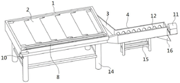
Referring to fig. 1-5, the utility model relates to a scrap discharge device for a machine tool workbench, which comprises a frame 1, wherein a plurality of turning plates 2 are rotatably connected on the inner surface of the frame 1; one end of the frame 1 is communicated with a falling groove 3; the bottom end of the falling groove 3 is communicated with a chip groove 4;
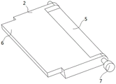
a notch 5 is arranged on one surface of the turning plate 2; a first clamping plate 6 is fixed on one end face of the turning plate 2; two adjacent turning plates 2 are clamped with the notch 5 through a first clamping plate 6;
a second clamping plate 17 is fixed on the inner side of the frame 1; the second clamping plate 17 is clamped with one of the turning plates 2 through the notches 5.
As shown in fig. 3, a first fluted disc 7 is fixed on one side of the turning plate 2; a transmission belt 8 is meshed and driven on the peripheral side surfaces of the first fluted discs; a second gear disc 9 is meshed and driven on the inner surface of the transmission belt 8; one side of the second fluted disc 9 penetrates through the frame 1 and is fixed with a rotating arm 10.
As shown in fig. 1, a servo motor 11 is fixed at one end of the chip groove 4; one end of the rotating shaft of the servo motor 11 penetrates through the chip groove 4 and is fixed with the auger blade 12 through the coupler.
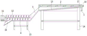
Wherein, as shown in fig. 2, the bottom of the falling chute 3 is fixed with an inclined plate 13; the bottom of the inclined plate 13 is fixed with a first supporting frame 14.
As shown in fig. 1, a second support frame 15 is fixed at the bottom of the chip groove 4; the bottom of the chip groove 4 is communicated with a chip outlet 16.
One specific application of this embodiment is: two adjacent turning plates 2 pass through notch 5 and the mutual joint of first cardboard 6, lathe during operation, the piece falls on a plurality of workstation surfaces that turn over the board 2 and constitute, rotate swinging boom 10, swinging boom 10 drives second fluted disc 9 and 8 meshing transmissions of drive belt, drive belt 8 drives first fluted disc 7 and makes and turn over board 2 upset, the piece falls hang plate 13 and falls to chip groove 4 through falling groove 3 from two adjacent clearances that turn over between the board 2, servo motor 11 drives auger blade 12 and carries the piece and discharge through chip outlet 16.
In the description herein, references to the description of "one embodiment," "an example," "a specific example," etc., mean that a particular feature, structure, material, or characteristic described in connection with the embodiment or example is included in at least one embodiment or example of the invention. In this specification, the schematic representations of the terms used above do not necessarily refer to the same embodiment or example. Furthermore, the particular features, structures, materials, or characteristics described may be combined in any suitable manner in any one or more embodiments or examples.
The preferred embodiments of the present invention disclosed above are intended only to help illustrate the present invention. The preferred embodiments are not intended to be exhaustive or to limit the invention to the precise embodiments disclosed. Obviously, many modifications and variations are possible in light of the above teaching. The embodiments were chosen and described in order to best explain the principles of the invention and its practical applications, to thereby enable others skilled in the art to best understand the invention for and utilize the invention. The present invention is limited only by the claims and their full scope and equivalents.
Claims (5)
1. A machine tool table chip evacuation device comprising a frame (1), characterized in that:
the inner surface of the frame (1) is rotatably connected with a plurality of turning plates (2); one end of the frame (1) is communicated with a falling groove (3); the bottom end of the falling groove (3) is communicated with a chip groove (4);
a notch (5) is formed in one surface of the turning plate (2); a first clamping plate (6) is fixed on one end face of the turning plate (2); two adjacent turning plates (2) are clamped with the notches (5) through first clamping plates (6);
a second clamping plate (17) is fixed on the inner side of the frame (1); the second clamping plate (17) is clamped with one of the turning plates (2) through the notch (5).
2. The machine tool workbench debris extraction apparatus of claim 1, wherein a first toothed disc (7) is fixed to one side of each of said plurality of flaps (2); a transmission belt (8) is meshed and driven on the peripheral side surfaces of the first fluted discs; a second fluted disc (9) is meshed and driven on the inner surface of the transmission belt (8); one side of the second fluted disc (9) penetrates through the frame (1) and is fixed with a rotating arm (10).
3. The machine tool workbench debris extraction device of claim 1, wherein a servo motor (11) is fixed at one end of the chip groove (4); one end of the rotating shaft of the servo motor (11) penetrates through the chip groove (4) and is fixed with the auger blade (12) through the coupler.
4. A machine tool table debris extraction device according to claim 1, wherein the bottom of the drop chute (3) is secured to a sloping plate (13); a first supporting frame (14) is fixed at the bottom of the inclined plate (13).
5. The machine tool workbench scrap discharge apparatus in accordance with claim 1, wherein a second support frame (15) is fixed at the bottom of said chip discharge groove (4); the bottom of the chip groove (4) is communicated with a chip outlet (16).
Priority Applications (1)
| Application Number | Priority Date | Filing Date | Title |
|---|---|---|---|
| CN201920354105.5U CN210099564U (en) | 2019-03-20 | 2019-03-20 | Scrap discharge device for machine tool workbench |
Applications Claiming Priority (1)
| Application Number | Priority Date | Filing Date | Title |
|---|---|---|---|
| CN201920354105.5U CN210099564U (en) | 2019-03-20 | 2019-03-20 | Scrap discharge device for machine tool workbench |
Publications (1)
| Publication Number | Publication Date |
|---|---|
| CN210099564U true CN210099564U (en) | 2020-02-21 |
Family
ID=69534172
Family Applications (1)
| Application Number | Title | Priority Date | Filing Date |
|---|---|---|---|
| CN201920354105.5U Active CN210099564U (en) | 2019-03-20 | 2019-03-20 | Scrap discharge device for machine tool workbench |
Country Status (1)
| Country | Link |
|---|---|
| CN (1) | CN210099564U (en) |
Cited By (2)
| Publication number | Priority date | Publication date | Assignee | Title |
|---|---|---|---|---|
| CN112719341A (en) * | 2020-12-24 | 2021-04-30 | 襄阳易日自动化设备有限公司 | Multi-spindle drilling machine capable of recycling waste materials |
| CN113681306A (en) * | 2021-08-12 | 2021-11-23 | 晟光科技股份有限公司 | Numerical control CNC processing corner processing apparatus |
-
2019
- 2019-03-20 CN CN201920354105.5U patent/CN210099564U/en active Active
Cited By (2)
| Publication number | Priority date | Publication date | Assignee | Title |
|---|---|---|---|---|
| CN112719341A (en) * | 2020-12-24 | 2021-04-30 | 襄阳易日自动化设备有限公司 | Multi-spindle drilling machine capable of recycling waste materials |
| CN113681306A (en) * | 2021-08-12 | 2021-11-23 | 晟光科技股份有限公司 | Numerical control CNC processing corner processing apparatus |
Similar Documents
| Publication | Publication Date | Title |
|---|---|---|
| CN204397361U (en) | Machined workbench | |
| CN210099564U (en) | Scrap discharge device for machine tool workbench | |
| CN108381274B (en) | Automatic processing machine tool with multi-track lane feeding | |
| CN211029207U (en) | Automatic cleaning device of machine tool workbench | |
| CN211803989U (en) | Drilling machine for plate processing | |
| CN105945584B (en) | A kind of brake disc processing unit (plant) | |
| CN105881023A (en) | Equipment for machining disc type workpieces | |
| CN212577530U (en) | Precision machine tool flexible to operate | |
| CN211361578U (en) | Chip removal device of gantry machining center | |
| CN211539534U (en) | Industrial automation has transport structure's equipment of polishing that punches | |
| CN112222446A (en) | Precision machine tool flexible to operate | |
| CN217799049U (en) | High-precision numerical control machining center for metal product production and machining | |
| CN218015947U (en) | Numerically-controlled drilling machine with self-cleaning function | |
| CN214351134U (en) | Turnover device for machining of machine tool parts | |
| CN211840157U (en) | Novel numerical control lathe device capable of automatically feeding and discharging | |
| CN211991882U (en) | Machine tool for machining | |
| CN208163212U (en) | A kind of automatic chip removal mechanism for numerical control fixed-girder planer-type milling machine | |
| CN105563228A (en) | Automatic service system for machine tool | |
| CN211890007U (en) | Prevent accumulational lathe material collecting device | |
| CN214213086U (en) | Two-shaft automatic machine tool feeding and discharging robot | |
| CN214445398U (en) | Utilize multistation milling cutter grinding machine of manipulator material loading | |
| CN216913105U (en) | Material moving and receiving device for boring and milling machine | |
| CN220388802U (en) | Dust removal cleaning device of vertical milling machine | |
| CN212527002U (en) | Scraping device for chain chip cleaner of machine tool | |
| CN211615026U (en) | Milling equipment for machining planet wheel |
Legal Events
| Date | Code | Title | Description |
|---|---|---|---|
| GR01 | Patent grant | ||
| GR01 | Patent grant | ||
| TR01 | Transfer of patent right |
Effective date of registration: 20210507 Address after: No. 100, Shanghai Songjiang District fluang Chang Road, Shanghai Patentee after: SHANGHAI HORNGSHIUE INDUSTRIAL Co.,Ltd. Address before: 221000 Jiangsu city of Xuzhou Province Academy of Quanshan District Road No. 26 Patentee before: JIANGSU JIANZHU INSTITUTE |
|
| TR01 | Transfer of patent right |