CN210079632U - Garbage disposal mechanical equipment - Google Patents
Garbage disposal mechanical equipment Download PDFInfo
- Publication number
- CN210079632U CN210079632U CN201920551114.3U CN201920551114U CN210079632U CN 210079632 U CN210079632 U CN 210079632U CN 201920551114 U CN201920551114 U CN 201920551114U CN 210079632 U CN210079632 U CN 210079632U
- Authority
- CN
- China
- Prior art keywords
- bevel gear
- rotating shaft
- groups
- sets
- motor
- Prior art date
- Legal status (The legal status is an assumption and is not a legal conclusion. Google has not performed a legal analysis and makes no representation as to the accuracy of the status listed.)
- Expired - Fee Related
Links
Images


Landscapes
- Processing Of Solid Wastes (AREA)
Abstract
The utility model discloses a refuse treatment mechanical equipment, the on-line screen storage device comprises a base, the compression storehouse is installed to the upper end of base, and the upper end in compression storehouse is provided with broken storehouse, the pan feeding mouth has been seted up to the upper end in broken storehouse, the inside upper end fixed mounting in broken storehouse has first motor, and the lower extreme of first motor is provided with first conical gear, the right-hand member fixedly connected with third motor of lead screw, the third motor is installed on the operation panel. The utility model discloses a be provided with two sets of broken wheel pair rubbish and carry out breakage earlier, the table volume that makes rubbish diminishes, the surface area increase, become more efficient when making landfill degradation and burning, through being provided with two sets of extrusion pieces, can compress the rubbish of broken completion, the volume that makes rubbish is littleer, be convenient for storage and transportation, the space that the occupation was stacked to rubbish has been saved greatly, go on simultaneously through smashing and compression, make the refuse treatment process become more swift, greatly increased work efficiency.
Description
Technical Field
The utility model relates to a mechanical equipment technical field specifically is a refuse treatment mechanical equipment.
Background
Rubbish is the solid waste who produces in human daily life and the production, and most refuse handling machinery is though a great variety at present, but generally can not the efficient carry out work, and rubbish if not carry out the breakage earlier, directly uses the mode of landfill or burning to handle, and the treatment effeciency is extremely low, secondly when rubbish has been handled the back, piles up to deposit and need occupy very big place, very extravagant space. To this end we propose a mechanical waste treatment plant to solve the above mentioned problems.
SUMMERY OF THE UTILITY MODEL
An object of the utility model is to provide a refuse treatment mechanical equipment to the work efficiency who proposes in solving above-mentioned background is not enough, and rubbish needs to carry out the breakage, the big problem of rubbish occupation space.
In order to achieve the above object, the utility model provides a following technical scheme: a garbage treatment mechanical device comprises a base, wherein a compression bin is installed at the upper end of the base, a crushing bin is arranged at the upper end of the compression bin, a feeding opening is formed in the upper end of the crushing bin, a first motor is fixedly installed at the upper end inside the crushing bin, a first bevel gear is arranged at the lower end of the first motor and meshed with a second bevel gear, the second bevel gear is fixedly installed on a first rotating shaft, the left end and the right end of the first rotating shaft are installed on the inner wall of the crushing bin through bearings, a third bevel gear is arranged on the first rotating shaft and meshed with a fourth bevel gear, the fourth bevel gear is fixedly installed on a second rotating shaft, the upper end and the lower end of the second rotating shaft are rotatably connected with the inner wall of the crushing bin through bearings, and a crushing wheel is fixedly installed on the second rotating shaft, the upper end of the compression bin is fixedly provided with a second motor, the lower end of the second motor is fixedly provided with a fifth bevel gear, the fifth bevel gear is meshed with a sixth bevel gear, the sixth bevel gear is fixedly arranged on a third rotating shaft, the left end and the right end of the third rotating shaft are rotatably connected with the inner wall of the compression bin through bearings, the third rotating shaft is fixedly provided with a seventh bevel gear, the seventh bevel gear is meshed with an eighth bevel gear, the lower end of the eighth bevel gear is connected with the upper end of a rotary disc through a fixed shaft, the rotary disc is fixedly arranged in the compression bin, the right side of the lower end of the rotary disc is hinged with a first connecting rod, the right end of the first connecting rod is hinged with the left end of a second connecting rod, the right end of the second connecting rod is hinged with an extrusion block, the lower end of the compression bin is provided with a discharge port, and the lower side of the discharge port is hinged with a, the right-hand member of first branch links to each other with the left end of loop bar is articulated, and the left end of loop bar articulates there is second branch, the lower extreme of second branch links to each other with the fixed block is articulated, the inside cover of loop bar right-hand member is equipped with the lead screw, the right-hand member fixedly connected with third motor of lead screw, the third motor is installed on the operation panel.
Preferably, the third bevel gear, the fourth bevel gear, the second rotating shaft and the crushing wheel are provided with two sets, the two sets of third bevel gears are installed on the first rotating shaft, the two sets of fourth bevel gears are installed on the two sets of second rotating shafts respectively, the two sets of third bevel gears and the two sets of fourth bevel gears are meshed with each other in a pairwise mode, the two sets of second rotating shafts are installed on the two sets of crushing wheels respectively, and the two sets of crushing wheels are meshed with each other.
Preferably, the seventh bevel gear, the eighth bevel gear, the rotating discs, the first connecting rods, the second connecting rods and the extrusion blocks are provided with two groups, the two groups of seventh bevel gears are all installed on the third rotating shaft, the two groups of seventh bevel gears and the two groups of eighth bevel gears are meshed with each other pairwise, the two groups of eighth bevel gears are installed on the two groups of rotating discs respectively, the first connecting rods are installed at the lower ends of the two groups of rotating discs respectively, the second connecting rods are installed on the two groups of first connecting rods respectively, and the two groups of second connecting rods are hinged to the two groups of extrusion blocks respectively.
Preferably, the compression bin is internally provided with a sliding chute, the inner side size of the sliding chute is equal to the outer side size of the extrusion block, and the extrusion block and the compression bin are in a sliding connection structure through the sliding chute.
Preferably, the lower extreme in compression storehouse has seted up square hole, the inboard size in square hole equals with the outside size of discharge gate, and the right-hand member of discharge gate passes through the pivot and installs the lower extreme in compression storehouse, the discharge gate sets up to rotating-structure.
Preferably, the right end of the inside of the loop bar is provided with a nut, the nut is matched with the screw rod, and the loop bar forms a telescopic structure through the nut and the screw rod.
Compared with the prior art, the beneficial effects of the utility model are that: according to the garbage disposal mechanical equipment, the garbage is firstly crushed by the two groups of crushing wheels, so that the surface volume of the garbage is reduced, the surface area is increased, and the garbage landfill degradation and combustion efficiency is improved; the two groups of extrusion blocks can compress the crushed garbage, so that the volume of the garbage is smaller, the garbage is convenient to store and transport, and the space occupied by stacking the garbage is greatly saved; through smashing and compressing simultaneously, make the refuse treatment process become more swift, greatly increased work efficiency.
Description of the drawings:
in order to more clearly illustrate the embodiments of the present invention or the technical solutions in the prior art, the drawings used in the description of the embodiments or the prior art will be briefly described below, it is obvious that the drawings in the following description are only some embodiments of the present invention, and for those skilled in the art, other drawings can be obtained according to these drawings without creative efforts.
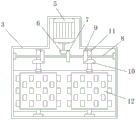
FIG. 1 is a schematic sectional view of the front view of the structure of the present invention;
FIG. 2 is a schematic side view of the structure of the present invention;
fig. 3 is a schematic bottom sectional view of the structure of fig. 1 at a-a according to the present invention;
fig. 4 is a schematic top sectional view of the structure at B-B in fig. 1 according to the present invention.
In the figure: 1. a base; 2. compressing the bin; 3. a crushing bin; 4. a feeding port; 5. a first motor; 6. a first bevel gear; 7. a second bevel gear; 8. a first rotating shaft; 9. a third bevel gear; 10. a fourth bevel gear; 11. a second rotating shaft; 12. a crushing wheel; 13. a second motor; 14. a fifth bevel gear; 15. a sixth bevel gear; 16. a third rotating shaft; 17. a seventh bevel gear; 18. an eighth bevel gear; 19. a turntable; 20. a first connecting rod; 21. a second connecting rod; 22. extruding the block; 23. a discharge port; 24. a first support bar; 25. a loop bar; 26. a second support bar; 27. a fixed block; 28. a screw rod; 29. a third motor; 30. an operation platform.
The specific implementation mode is as follows:
the technical solutions in the embodiments of the present invention will be described clearly and completely with reference to the accompanying drawings in the embodiments of the present invention, and it is obvious that the described embodiments are only some embodiments of the present invention, not all embodiments. Based on the embodiments in the present invention, all other embodiments obtained by a person skilled in the art without creative work belong to the protection scope of the present invention.
Referring to fig. 1-4, the present invention provides an embodiment: a garbage disposal mechanical device comprises a base 1, a compression bin 2 is installed at the upper end of the base 1, a crushing bin 3 is arranged at the upper end of the compression bin 2, a feeding port 4 is formed at the upper end of the crushing bin 3, a first motor 5 is fixedly installed at the upper end inside the crushing bin 3, a first bevel gear 6 is arranged at the lower end of the first motor 5, the first bevel gear 6 is meshed with a second bevel gear 7, the second bevel gear 7 is fixedly installed on a first rotating shaft 8, the left end and the right end of the first rotating shaft 8 are both installed on the inner wall of the crushing bin 3 through bearings, a third bevel gear 9 is arranged on the first rotating shaft 8, the third bevel gear 9 is meshed with a fourth bevel gear 10, the fourth bevel gear 10 is fixedly installed on a second rotating shaft 11, the upper end and the lower end of the second rotating shaft 11 are both rotatably connected with the inner wall of the crushing bin 3 through bearings, a crushing wheel 12 is fixedly installed on the second rotating shaft 11, the structure enables the device to crush garbage, increases the surface area of the garbage, enables the garbage to be more easily buried, degraded or burned, and greatly increases the garbage treatment efficiency;
a second motor 13 is fixedly installed at the upper end of the compression bin 2, a fifth bevel gear 14 is fixedly installed at the lower end of the second motor 13, the fifth bevel gear 14 is meshed with a sixth bevel gear 15, the sixth bevel gear 15 is fixedly installed on a third rotating shaft 16, the left end and the right end of the third rotating shaft 16 are rotatably connected with the inner wall of the compression bin 2 through bearings, a seventh bevel gear 17 is fixedly installed on the third rotating shaft 16, the seventh bevel gear 17 is meshed with an eighth bevel gear 18, the lower end of the eighth bevel gear 18 is connected with the upper end of a rotating disc 19 through a fixed shaft, the rotating disc 19 is fixedly installed inside the compression bin 2, a first connecting rod 20 is hinged to the right side of the lower end of the rotating disc 19, the right end of the first connecting rod 20 is hinged to the left end of a second connecting rod 21, an extrusion block 22 is hinged to the right end of the second connecting rod 21, the seventh bevel gear 17, the eighth bevel gear 18, the turntable 19, the first connecting rod 20, the second connecting rod 21 and the extrusion block 22 are all provided with two groups, two groups of seventh bevel gears 17 are all arranged on the third rotating shaft 16, two groups of seventh bevel gears 17 and two groups of eighth bevel gears 18 are meshed with each other in pairs, and two groups of eighth bevel gears 18 are respectively arranged on two groups of turntables 19, the lower ends of the two groups of turntables 19 are respectively provided with a first connecting rod 20, and the two groups of first connecting rods 20 are respectively provided with a second connecting rod 21, the two groups of second connecting rods 21 are respectively hinged with two groups of extrusion blocks 22, the interior of the compression bin 2 is provided with a sliding chute, the inner side dimension of the sliding chute is equal to the outer side dimension of the extrusion blocks 22, the extrusion blocks 22 and the compression bin 2 are in a sliding connection structure through the sliding chute, the structure can compress the crushed garbage, so that the size of the garbage is reduced, the garbage is easier to transport, and the placement space is saved;
the lower end of the compression bin 2 is provided with a discharge hole 23, the lower side of the discharge hole 23 is hinged with a first support rod 24, the right end of the first support rod 24 is hinged with the left end of a sleeve rod 25, the left end of the sleeve rod 25 is hinged with a second support rod 26, the lower end of the second support rod 26 is hinged with a fixed block 27, a screw rod 28 is sleeved inside the right end of the sleeve rod 25, the right end of the screw rod 28 is fixedly connected with a third motor 29, the third motor 29 is installed on an operating platform 30, the lower end of the compression bin 2 is provided with a square hole, the inner side size of the square hole is equal to the outer side size of the discharge hole 23, the right end of the discharge hole 23 is installed at the lower end of the compression bin 2 through a rotating shaft, the discharge hole 23 is arranged in a rotating structure, the right end inside the sleeve rod 25 is provided with a screw nut, the screw nut is matched with the, the workpiece can be taken out more easily, so that the working steps are simpler, and the working efficiency is improved.
The working principle is as follows: when the garbage crusher is used, a switch of a first motor 5 on an operation table 30 is firstly turned on, the first motor 5 can drive a second bevel gear 7 to rotate through a first bevel gear 6, the first rotating shaft 8 can be driven to rotate by the second bevel gear 7 because the second bevel gear 7 is arranged on a first rotating shaft 8, then two groups of third bevel gears 9 on the first rotating shaft 8 can drive two groups of fourth bevel gears 10 which are respectively meshed to rotate, two groups of second rotating shafts 11 can rotate along with the two groups of fourth bevel gears 10, two groups of crushing wheels 12 which are arranged on the two groups of second rotating shafts 11 start to rotate, at the moment, garbage is poured into the garbage crusher from a material inlet 4, the garbage can fall into a crushing bin 3, the two groups of crushing wheels 12 can crush the garbage, the crushed garbage can fall into a compression bin 2 and is accumulated inside the compression bin 2, after the garbage is crushed, the size of the garbage is reduced, the surface of the garbage is enlarged, when the garbage is filled or burned, the degradation speed is accelerated, so that the garbage treatment efficiency is improved;
then the switch of the first motor 5 is turned off, the switch of the second motor 13 on the operation table 30 is turned on, at this time, the second motor 13 starts to work, the fifth bevel gear 14 installed on the second motor 13 drives the sixth bevel gear 15 to start to rotate, and at the same time, because the sixth bevel gear 15 is installed on the third rotating shaft 16, the third rotating shaft 16 is driven by the sixth bevel gear 15, so that the two sets of seventh bevel gears 17 on the third rotating shaft 16 start to rotate, because the second set of seventh bevel gears 17 are respectively engaged with the two sets of eighth bevel gears 18 in pairs, the two sets of eighth bevel gears 18 start to rotate, and simultaneously drive the two sets of rotating discs 19 respectively connected with the two sets of eighth bevel gears 18 to rotate, when the two sets of rotating discs 19 rotate, the two sets of first connecting rods 20 respectively connected to the two sets of rotating discs 19 respectively pull the two sets of second connecting rods 21, and then the two sets of second connecting rods 21 drive the two sets of squeezing blocks 22 to move, the two groups of extrusion blocks 22 extrude the garbage, and the garbage pile is compressed by reciprocating work, so that the size of the garbage pile is reduced, the garbage pile is easier to store or transport, the space is saved, and the working efficiency is greatly improved;
after rubbish compression finishes, close the switch of second motor 13, open the switch of third motor 29 on the operation panel 30, third motor 29 can drive lead screw 28 and rotate this moment, because of the inside screw that is provided with of loop bar 25 that is connected with lead screw 28, so loop bar 25 can be along with the rotation of lead screw 28 and shrink backward, loop bar 25 articulated first branch 24 and second branch 26 can be by the pulling backward afterwards, then first branch 24 can stimulate discharge gate 23 downwards, make the rubbish of compressed along with discharge gate 23 roll-off, make it can be collected by the manual work, this device is full mechanization, make refuse treatment become more convenient and fast, greatly increased work efficiency, do above the utility model discloses a whole theory of works.
It is obvious to a person skilled in the art that the invention is not restricted to details of the above-described exemplary embodiments, but that it can be implemented in other specific forms without departing from the spirit or essential characteristics of the invention. The present embodiments are therefore to be considered in all respects as illustrative and not restrictive, the scope of the invention being indicated by the appended claims rather than by the foregoing description, and all changes which come within the meaning and range of equivalency of the claims are therefore intended to be embraced therein. Any reference sign in a claim should not be construed as limiting the claim concerned.
Claims (6)
1. A refuse treatment mechanical device, comprising a base (1), characterized in that: the upper end of the base (1) is provided with a compression bin (2), the upper end of the compression bin (2) is provided with a crushing bin (3), the upper end of the crushing bin (3) is provided with a feeding hole (4), the upper end inside the crushing bin (3) is fixedly provided with a first motor (5), the lower end of the first motor (5) is provided with a first bevel gear (6), the first bevel gear (6) is meshed with a second bevel gear (7), the second bevel gear (7) is fixedly arranged on a first rotating shaft (8), the left end and the right end of the first rotating shaft (8) are both arranged on the inner wall of the crushing bin (3) through bearings, the first rotating shaft (8) is provided with a third bevel gear (9), the third bevel gear (9) is meshed with a fourth bevel gear (10), and the fourth bevel gear (10) is fixedly arranged on a second rotating shaft (11), the upper end and the lower end of a second rotating shaft (11) are rotatably connected with the inner wall of a crushing bin (3) through bearings, a crushing wheel (12) is fixedly mounted on the second rotating shaft (11), a second motor (13) is fixedly mounted at the upper end of a compression bin (2), a fifth bevel gear (14) is fixedly mounted at the lower end of the second motor (13), the fifth bevel gear (14) is meshed with a sixth bevel gear (15), the sixth bevel gear (15) is fixedly mounted on a third rotating shaft (16), the left end and the right end of the third rotating shaft (16) are rotatably connected with the inner wall of the compression bin (2) through bearings, a seventh bevel gear (17) is fixedly mounted on the third rotating shaft (16), the seventh bevel gear (17) is meshed with an eighth bevel gear (18), the lower end of the eighth bevel gear (18) is connected with the upper end of a rotating shaft (19) through a fixing shaft, the rotary table (19) is fixedly arranged in the compression bin (2), the right side of the lower end of the rotary table (19) is hinged with a first connecting rod (20), the right end of the first connecting rod (20) is hinged with the left end of the second connecting rod (21), the right end of the second connecting rod (21) is hinged with an extrusion block (22), the lower end of the compression bin (2) is provided with a discharge hole (23), and the lower side of the discharge port (23) is hinged with a first supporting rod (24), the right end of the first supporting rod (24) is hinged with the left end of the loop bar (25), the left end of the loop bar (25) is hinged with a second supporting bar (26), the lower end of the second supporting bar (26) is hinged with a fixed block (27), the inside cover of loop bar (25) right-hand member is equipped with lead screw (28), the right-hand member fixedly connected with third motor (29) of lead screw (28), third motor (29) are installed on operation panel (30).
2. A waste disposal plant according to claim 1, wherein: third bevel gear (9), fourth bevel gear (10), second pivot (11) and broken wheel (12) all are provided with two sets ofly, two sets of third bevel gear (9) are all installed on first pivot (8), two sets of fourth bevel gear (10) are installed respectively on two sets of second pivot (11), two liang of intermeshing of two sets of third bevel gear (9) and two sets of fourth bevel gear (10), install respectively on two sets of broken wheels (12) on two sets of second pivots (11), and two sets of broken wheel (12) intermeshing.
3. A waste disposal plant according to claim 1, wherein: the novel extrusion device is characterized in that the seventh bevel gear (17), the eighth bevel gear (18), the rotary table (19), the first connecting rod (20), the second connecting rod (21) and the extrusion block (22) are arranged in two groups, the two groups of seventh bevel gears (17) are arranged on the third rotary shaft (16), the two groups of seventh bevel gears (17) and the two groups of eighth bevel gears (18) are meshed with each other in a pairwise mode, the two groups of eighth bevel gears (18) are arranged on the two groups of rotary tables (19) respectively, the first connecting rods (20) are arranged at the lower ends of the two groups of rotary tables (19) respectively, the second connecting rods (21) are arranged on the two groups of first connecting rods (20) respectively, and the two groups of second connecting rods (21) are connected with the two groups of extrusion blocks (22) in.
4. A waste disposal plant according to claim 1, wherein: the compression bin (2) is internally provided with a sliding groove, the inner side size of the sliding groove is equal to the outer side size of the extrusion block (22), and the extrusion block (22) is in a sliding connection structure with the compression bin (2) through the sliding groove.
5. A waste disposal plant according to claim 1, wherein: the lower extreme in compression storehouse (2) has been seted up square hole, the inboard size in square hole equals with the outside size of discharge gate (23), and the lower extreme in compression storehouse (2) is installed through the pivot to the right-hand member of discharge gate (23), discharge gate (23) set up to rotating-structure.
6. A waste disposal plant according to claim 1, wherein: the right-hand member of loop bar (25) inside is provided with the screw, and screw and lead screw (28) mutually support, loop bar (25) constitute extending structure through screw and lead screw (28).
Priority Applications (1)
| Application Number | Priority Date | Filing Date | Title |
|---|---|---|---|
| CN201920551114.3U CN210079632U (en) | 2019-04-22 | 2019-04-22 | Garbage disposal mechanical equipment |
Applications Claiming Priority (1)
| Application Number | Priority Date | Filing Date | Title |
|---|---|---|---|
| CN201920551114.3U CN210079632U (en) | 2019-04-22 | 2019-04-22 | Garbage disposal mechanical equipment |
Publications (1)
| Publication Number | Publication Date |
|---|---|
| CN210079632U true CN210079632U (en) | 2020-02-18 |
Family
ID=69475297
Family Applications (1)
| Application Number | Title | Priority Date | Filing Date |
|---|---|---|---|
| CN201920551114.3U Expired - Fee Related CN210079632U (en) | 2019-04-22 | 2019-04-22 | Garbage disposal mechanical equipment |
Country Status (1)
| Country | Link |
|---|---|
| CN (1) | CN210079632U (en) |
Cited By (2)
| Publication number | Priority date | Publication date | Assignee | Title |
|---|---|---|---|---|
| CN111659697A (en) * | 2020-05-25 | 2020-09-15 | 生态环境部华南环境科学研究所 | Compaction processing apparatus of industry organic solid waste material resource utilization |
| CN112191298A (en) * | 2020-09-25 | 2021-01-08 | 安徽省恒金矿业有限公司 | Low-consumption energy-saving limestone crushing device |
-
2019
- 2019-04-22 CN CN201920551114.3U patent/CN210079632U/en not_active Expired - Fee Related
Cited By (3)
| Publication number | Priority date | Publication date | Assignee | Title |
|---|---|---|---|---|
| CN111659697A (en) * | 2020-05-25 | 2020-09-15 | 生态环境部华南环境科学研究所 | Compaction processing apparatus of industry organic solid waste material resource utilization |
| CN111659697B (en) * | 2020-05-25 | 2021-07-20 | 生态环境部华南环境科学研究所 | Compaction processing apparatus of industry organic solid waste material resource utilization |
| CN112191298A (en) * | 2020-09-25 | 2021-01-08 | 安徽省恒金矿业有限公司 | Low-consumption energy-saving limestone crushing device |
Similar Documents
| Publication | Publication Date | Title |
|---|---|---|
| CN210146646U (en) | House construction is with building rubbish compressor arrangement | |
| CN210079632U (en) | Garbage disposal mechanical equipment | |
| CN108262141A (en) | A kind of building waste fast-crushing device | |
| CN112407675A (en) | Intelligent kitchen waste treatment device capable of being efficiently recycled | |
| CN212975291U (en) | Broken packing all-in-one of domestic waste | |
| CN209254860U (en) | A kind of waste paper packing apparatus | |
| CN213198921U (en) | Broken compaction device of rubbish | |
| CN210474114U (en) | Movable fallen leaf crushing compressor | |
| CN212237591U (en) | Environment-friendly equipment for garbage disposal | |
| CN117161061A (en) | Urban household garbage crushing, screening and forming treatment system | |
| CN210936416U (en) | Industrial waste handles with categorised compression baling equipment of being convenient for | |
| CN214488268U (en) | Solid waste handles with packing compressor arrangement | |
| CN213316784U (en) | Garbage crushing equipment for garbage classification | |
| CN212979319U (en) | Be used for property service rubbish splitter | |
| CN212651961U (en) | Torsion type processor for auxiliary crushing treatment of canned garbage | |
| CN113249166A (en) | Edible oil squeezing equipment and edible oil squeezing process | |
| CN208512749U (en) | A kind of building waste fast-crushing device | |
| CN207025429U (en) | A kind of bulk organic automatic garbage crushing device | |
| CN217803480U (en) | Fluid pressure type rubbish compressor arrangement with automatic edulcoration structure | |
| CN218516821U (en) | Weaving equipment convenient to collect waste material | |
| CN220361245U (en) | Vertical organic waste treatment device | |
| CN212221299U (en) | Garbage transporting device for garbage power generation | |
| CN221310925U (en) | Garbage crushing device | |
| CN214211713U (en) | Garbage disposal device for building | |
| CN113509987B (en) | Garbage environment-friendly treatment equipment |
Legal Events
| Date | Code | Title | Description |
|---|---|---|---|
| GR01 | Patent grant | ||
| GR01 | Patent grant | ||
| CF01 | Termination of patent right due to non-payment of annual fee | ||
| CF01 | Termination of patent right due to non-payment of annual fee |
Granted publication date: 20200218 Termination date: 20210422 |