CN210045065U - Stench waste gas treatment device - Google Patents
Stench waste gas treatment device Download PDFInfo
- Publication number
- CN210045065U CN210045065U CN201920310338.5U CN201920310338U CN210045065U CN 210045065 U CN210045065 U CN 210045065U CN 201920310338 U CN201920310338 U CN 201920310338U CN 210045065 U CN210045065 U CN 210045065U
- Authority
- CN
- China
- Prior art keywords
- fixed
- treatment device
- deodorization
- gas treatment
- ring
- Prior art date
- Legal status (The legal status is an assumption and is not a legal conclusion. Google has not performed a legal analysis and makes no representation as to the accuracy of the status listed.)
- Expired - Fee Related
Links
Images


Landscapes
- Treating Waste Gases (AREA)
Abstract
The utility model discloses an odor waste gas treatment device, be fixed with the retainer plate on the inner wall of cartridge filter, evenly be fixed with four threaded rods on the retainer plate, the top alternate of threaded rod has the clamping ring, be fixed with the nut on the threaded rod in the clamping ring outside, accompany a plurality of layers of gauze between clamping ring and the retainer plate, the inner welding of cartridge filter has the adsorption tank of cuboid structure, set up the fixed slot of two sets of slopes on the both sides inner wall of adsorption tank, all insert in the fixed slot and be equipped with the active carbon adsorption plate, the adsorption tank communicates in a deodorization section of thick bamboo through the air duct that is equipped with, the top center department of a deodorization section of thick bamboo is fixed with the motor. Has the advantages that: through being connected with the adsorption tank on the cartridge filter, be connected with the deodorization section of thick bamboo in one side of adsorption tank, filter earlier particulate impurity, improve gas quality, then eliminate hydrogen sulfide through absorption and chemical reaction, sulfur dioxide is odorous gaseous, and the hierarchical treatment is more accurate, is favorable to thoroughly eliminating odorous gas.
Description
Technical Field
The utility model relates to a waste gas treatment technical field specifically is a device is administered to stench waste gas.
Background
The waste gas refers to toxic and harmful gas discharged by human in the production and living process. Especially chemical plants, steel plants, pharmaceutical plants, coking plants, oil refineries and the like, and living waste gas brought by human life, the discharged waste gas has large smell, contains a large amount of sulfur dioxide, hydrogen sulfide, hydrocarbon and the like, seriously pollutes the environment and affects the human health.
The stench waste gas treatment device that uses at present is single to having the gas treatment mode of smell, and the structure is complicated, and the level of being inconvenient for filters particulate impurity, and is difficult to the quick replacement filter screen, causes the filter screen to block up easily, and the effective improvement of being inconvenient for still sends the stench after the discharge, seriously influences the surrounding gas environment.
SUMMERY OF THE UTILITY MODEL
The utility model aims to provide a: aiming at the problems existing at present, the malodorous waste gas treatment device is provided.
In order to realize the purpose, the utility model discloses a technical scheme is:
a malodorous waste gas treatment device comprises a cylindrical filter cartridge, a filter device and a purification device, wherein the filter device is arranged in the filter cartridge, the filter device comprises a fixed ring, a pressing ring, threaded rods and a plurality of gauzes, the fixed ring is fixed on the inner wall of the filter cartridge, four threaded rods are uniformly fixed on the fixed ring, the pressing ring is inserted at the top end of each threaded rod, nuts are fixed on the threaded rods outside the pressing ring, a plurality of layers of gauzes are clamped between the pressing ring and the fixed ring for rapidly replacing particle impurities with different apertures, an adsorption box with a cuboid structure is welded at the inner end of the filter cartridge, two groups of inclined fixed slots are formed on the inner walls of two sides of the adsorption box, activated carbon adsorption plates are inserted in the fixed slots and used for adsorbing odor gas, and the purification device is arranged at the other side of the adsorption box, purifier includes a deodorization section of thick bamboo and motor, the adsorption tank through the air duct that is equipped with communicate in the deodorization section of thick bamboo, the top center department of deodorization section of thick bamboo is fixed with the motor for purify, stir simultaneously, improve reaction rate and thoroughness.
Preferably, the output end of the motor extends into the deodorizing cylinder and is welded with a stirring rod.
Preferably, a motor switch is arranged at the center of the outer wall of the deodorization cylinder, and the motor switch is electrically connected with the motor.
Preferably, the upper part and the lower part of the motor switch and the deodorization cylinder are respectively communicated with a reaction liquid injection pipe and a drain pipe.
Preferably, a filter screen is fixed at the inner end of the drain pipe and positioned on the deodorizing cylinder.
Preferably, the filter cylinder and the deodorization cylinder are respectively communicated with an air inlet pipe and an air outlet pipe.
Preferably, the gas guide pipe is provided with a valve, a hydrogen sulfide detector and a sulfur dioxide detector.
Preferably, the fixing ring, the pressing ring and the gauze are all of circular structures, and the fixing ring and the pressing ring are both hollow.
Since the technical scheme is used, the beneficial effects of the utility model are that: through be connected with the adsorption tank on the cartridge filter, be connected with the deodorization section of thick bamboo in one side of adsorption tank, filter particle impurity earlier, improve gas quality, then eliminate hydrogen sulfide through absorption and chemical reaction, sulfur dioxide is odorous gaseous, the layering is administered, the more precision, be favorable to thoroughly eliminating odorous gas, but through be provided with quick replacement and the gauze of dismantling in the cartridge filter, be used for containing the granule size in the gas and carrying out quick replacement, filterable more careful, through be provided with active carbon adsorption plate and reaction liquid respectively in adsorption tank and deodorization box, adopt physics and two kinds of processing methods of chemistry, absorb odor gas and conversion, be convenient for thoroughly deodorize.
Drawings
Fig. 1 is a schematic view of the overall structure of the present invention;
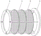
FIG. 2 is a schematic structural view of the filtering apparatus of the present invention;
fig. 3 is a schematic view of the connection structure of the filter cartridge and the adsorption box of the present invention;
fig. 4 is a schematic structural view of the inner wall of the adsorption box of the present invention.
In the figure: 1. a filter cartridge; 2. an adsorption tank; 3. a stationary ring; 4. pressing a ring; 5. a threaded rod; 6. a screen; 7. an activated carbon adsorption plate; 8. a deodorizing cylinder; 9. a motor; 10. a stirring rod; 11. a motor switch; 12. a reaction liquid injection pipe; 13. a drain pipe; 14. filtering with a screen; 15. an air duct; 16. an exhaust pipe; 17. an air inlet pipe.
Detailed Description
In order to make the purpose, technical solution and advantages of the embodiments of the present invention clearer, the accompanying drawings in the embodiments of the present invention are combined below to clearly and completely describe the technical solution in the embodiments of the present invention, and it is obvious that the described embodiments are some embodiments of the present invention, rather than all embodiments, based on the embodiments in the present invention, all other embodiments obtained by a person of ordinary skill in the art without creative work belong to the scope of the present invention.
Referring to fig. 1-4, the utility model provides a technical scheme, a malodorous waste gas treatment device, comprising a cylindrical filter cartridge 1, a filtering device and a purifying device, wherein the filtering device is arranged inside the filter cartridge 1, the filtering device comprises a fixed ring 3, a clamping ring 4, a threaded rod 5 and a plurality of gauzes 6, the fixed ring 3 is fixed on the inner wall of the filter cartridge 1, four threaded rods 5 are uniformly fixed on the fixed ring 3, the clamping ring 4 is inserted on the top end of the threaded rod 5, a nut is fixed on the threaded rod 5 outside the clamping ring 4, a plurality of layers of gauzes 6 are fixed between the clamping ring 4 and the fixed ring 3, the absorbing box 2 with a cuboid structure is welded at the inner end of the filter cartridge 1, two groups of inclined fixed grooves are arranged on the inner walls at two sides of the absorbing box 2, an active carbon absorbing plate 7 is inserted in the fixed grooves, the absorbing box is convenient to be replaced and fixed, the purifying device is, purifier includes a deodorization section of thick bamboo 8 and motor 9, and adsorption tank 2 communicates in a deodorization section of thick bamboo 8 through the air duct 15 that is equipped with, and the top center department of a deodorization section of thick bamboo 8 is fixed with motor 9 for the stirring improves reaction efficiency.
Preferably, the output end of the motor 9 extends into the interior of the deodorizing cylinder 8 and is welded with a stirring rod 10 for stirring.
Preferably, the center of the outer wall of the deodorizing cylinder 8 is provided with a motor switch 11, and the motor switch 11 is electrically connected with the motor 9, so that the control is convenient.
Preferably, a reaction liquid injection pipe 12 and a drain pipe 13 are respectively communicated with the upper and lower sides of the motor switch 11 and the deodorization cylinder 8, and used for injecting and discharging the reaction liquid.
Preferably, a screen 14 is fixed to the inner end of the drain pipe 13 and on the deodorizing tank 8 to prevent clogging of the drain pipe 13 due to crystal deposition.
Preferably, the filter cartridge 1 and the deodorizing cartridge 8 are respectively communicated with an intake pipe 17 and an exhaust pipe 16 for intake and exhaust.
Preferably, the gas guide tube 15 is provided with a valve, a hydrogen sulfide detector and a sulfur dioxide detector for detecting the concentration.
Preferably, the fixing ring 3, the pressing ring 4 and the gauze 6 are all of circular structures, and the fixing ring 3 and the pressing ring 4 are both hollow, so that ventilation is facilitated.
In this embodiment, the operation process and the deodorization principle of the malodorous waste gas treatment device are as follows:
the operation process is as follows:
step one, adding a sodium hydroxide solution into the deodorizing cylinder 8, wherein the solubility of the sodium hydroxide solution can be increased progressively according to the content of hydrogen sulfide and sulfur dioxide in the waste gas, inserting the activated carbon adsorption plate 7 into a fixed groove in the adsorption box 2, and connecting a pipeline for discharging the waste gas to the air inlet pipe 17.
Step two: and opening a valve on the gas guide pipe 15, and observing the concentration content information detected on the hydrogen sulfide detector and the sulfur dioxide detector.
The deodorization principle is as follows: waste gas enters a filter cylinder 1 and is filtered by a gauze 6, the aperture size of the gauze 6 is selected according to the particle size, when the filter is replaced, a nut on a threaded rod 5 is detached, the gauze 6 with proper aperture is moved to the outermost side and is tightly attached to the inner wall of a clamping ring 4, then the nut is screwed for fixing, after the impurity is filtered, the waste gas absorbs partial fine particles, carbon monoxide, sulfur dioxide, hydrogen sulfide and other harmful odor gases by an active carbon adsorption plate 7, the absorbed waste gas enters a sodium hydroxide solution by an air duct 15, the sulfur dioxide, the hydrogen sulfide and the hydrogen sulfide react with each other to generate sodium sulfite sediment and sodium sulfide crystals respectively, a motor 9 is started to drive a stirring rod 10 to stir in the chemical reaction process, the reaction efficiency is improved, meanwhile, the thorough reaction is facilitated, the generated crystals are remained in the sodium hydroxide solution, and the odor-removed gas is discharged by an exhaust pipe, when the sodium hydroxide solution is saturated, the solubility of the sodium hydroxide solution begins to decrease, and then a valve on the drain pipe 13 is opened to drain the low-concentration solution for replacement.
The above description is only for the specific embodiments of the present invention, but the protection scope of the present invention is not limited thereto, and any person skilled in the art can easily think of the changes or substitutions within the technical scope of the present invention, and all should be covered within the protection scope of the present invention. Therefore, the protection scope of the present invention shall be subject to the protection scope of the claims.
Claims (8)
1. The utility model provides a device is administered to stench waste gas, includes cartridge filter (1), filter equipment and the purifier of cylinder structure, its characterized in that: the filter device is arranged in the filter cartridge (1) and comprises a fixed ring (3), a clamping ring (4), threaded rods (5) and a plurality of gauzes (6), the fixed ring (3) is fixed on the inner wall of the filter cartridge (1), the four threaded rods (5) are uniformly fixed on the fixed ring (3), the clamping ring (4) is inserted at the top end of the threaded rods (5), nuts are fixed on the threaded rods (5) outside the clamping ring (4), a plurality of layers of gauzes (6) are clamped between the clamping ring (4) and the fixed ring (3), the adsorption tank (2) with a cuboid structure is welded at the inner end of the filter cartridge (1), two groups of inclined fixed grooves are formed in the inner walls of the two sides of the adsorption tank (2), and an activated carbon adsorption plate (7) is inserted in each fixed groove, the opposite side of adsorption box (2) is provided with purifier, purifier includes a deodorization section of thick bamboo (8) and motor (9), adsorption box (2) through air duct (15) that are equipped with communicate in deodorization section of thick bamboo (8), the top center department of deodorization section of thick bamboo (8) is fixed with motor (9).
2. The malodorous exhaust gas treatment device as claimed in claim 1, wherein: the output end of the motor (9) extends into the interior of the deodorization cylinder (8) and is welded with a stirring rod (10).
3. The malodorous exhaust gas treatment device as claimed in claim 2, wherein: the deodorization device is characterized in that a motor switch (11) is arranged at the center of the outer wall of the deodorization cylinder (8), and the motor switch (11) is electrically connected with the motor (9).
4. The malodorous exhaust gas treatment device as claimed in claim 3, wherein: the upper part and the lower part of the motor switch (11) are respectively communicated with a reaction liquid injection pipe (12) and a drain pipe (13) which are positioned on the deodorization cylinder (8).
5. The malodorous exhaust gas treatment device as claimed in claim 4, wherein: the inner end of the drain pipe (13) is positioned on the deodorizing cylinder (8) and is fixed with a filter screen (14).
6. The malodorous exhaust gas treatment device as claimed in claim 1, wherein: the filter cartridge (1) and the deodorization cylinder (8) are respectively communicated with an air inlet pipe (17) and an air outlet pipe (16).
7. The malodorous exhaust gas treatment device as claimed in claim 1, wherein: and the gas guide pipe (15) is provided with a valve, a hydrogen sulfide detector and a sulfur dioxide detector.
8. The malodorous exhaust gas treatment device as claimed in claim 1, wherein: the fixing ring (3), the pressing ring (4) and the gauze (6) are both of circular structures, and the fixing ring (3) and the pressing ring (4) are both of hollow shapes.
Priority Applications (1)
| Application Number | Priority Date | Filing Date | Title |
|---|---|---|---|
| CN201920310338.5U CN210045065U (en) | 2019-03-12 | 2019-03-12 | Stench waste gas treatment device |
Applications Claiming Priority (1)
| Application Number | Priority Date | Filing Date | Title |
|---|---|---|---|
| CN201920310338.5U CN210045065U (en) | 2019-03-12 | 2019-03-12 | Stench waste gas treatment device |
Publications (1)
| Publication Number | Publication Date |
|---|---|
| CN210045065U true CN210045065U (en) | 2020-02-11 |
Family
ID=69378715
Family Applications (1)
| Application Number | Title | Priority Date | Filing Date |
|---|---|---|---|
| CN201920310338.5U Expired - Fee Related CN210045065U (en) | 2019-03-12 | 2019-03-12 | Stench waste gas treatment device |
Country Status (1)
| Country | Link |
|---|---|
| CN (1) | CN210045065U (en) |
Cited By (3)
| Publication number | Priority date | Publication date | Assignee | Title |
|---|---|---|---|---|
| CN111437695A (en) * | 2020-04-14 | 2020-07-24 | 福建省浩氧环境科技有限公司 | VOC waste gas treatment device and use method thereof |
| CN114432850A (en) * | 2021-12-29 | 2022-05-06 | 南通全昂等离子体科技有限公司 | Plasma deodorization exhaust treatment system with multi-stage filtration function |
| CN116651155A (en) * | 2023-07-20 | 2023-08-29 | 江苏民生重工有限公司 | Tail gas absorbing device of chemical industry benzyl alcohol production for environmental protection |
-
2019
- 2019-03-12 CN CN201920310338.5U patent/CN210045065U/en not_active Expired - Fee Related
Cited By (3)
| Publication number | Priority date | Publication date | Assignee | Title |
|---|---|---|---|---|
| CN111437695A (en) * | 2020-04-14 | 2020-07-24 | 福建省浩氧环境科技有限公司 | VOC waste gas treatment device and use method thereof |
| CN114432850A (en) * | 2021-12-29 | 2022-05-06 | 南通全昂等离子体科技有限公司 | Plasma deodorization exhaust treatment system with multi-stage filtration function |
| CN116651155A (en) * | 2023-07-20 | 2023-08-29 | 江苏民生重工有限公司 | Tail gas absorbing device of chemical industry benzyl alcohol production for environmental protection |
Similar Documents
| Publication | Publication Date | Title |
|---|---|---|
| CN210045065U (en) | Stench waste gas treatment device | |
| CN201067664Y (en) | Cleaning treatment device for discharging waste gas | |
| CN212396201U (en) | Chemical gas recovery and purification device | |
| CN111895428A (en) | Decarbonization device for industrial waste gas treatment | |
| CN111701353A (en) | Mechanical cutting tail gas processing apparatus | |
| CN110280117B (en) | Centrifugal oxidation method and micro-nano bubble VOCs (volatile organic chemicals) processing system | |
| CN104587786B (en) | A kind of chemical industry and pharmaceuticals industry catalytic converter | |
| CN108543404A (en) | A kind of injection molding machine emission-control equipment of avoidable secondary pollution | |
| CN108579346B (en) | Waste gas multistage filtration processing apparatus | |
| CN217220825U (en) | Cylindrical continuous motion adsorption bed separator | |
| CN116262189A (en) | Cylindrical continuous motion adsorbent bed separator for waste gas treatment | |
| CN211659684U (en) | Chemical filtering and high-energy ion photocatalysis combined deodorization device | |
| CN207856604U (en) | A kind of organic waste gas treatment device | |
| CN208493655U (en) | A kind of efficient exhaust gas processing device | |
| RU2536749C2 (en) | Integrated device to clean exhaust gases of marine engine | |
| CN220360980U (en) | Microorganism absorption, decomposition and deodorization device | |
| CN104667688B (en) | A kind of industrial waste-gas purifier | |
| CN217677145U (en) | Flue gas desulfurization effluent treatment plant | |
| CN219072566U (en) | Exhaust gas treatment device | |
| CN111151090A (en) | Comprehensive treatment method for waste water and waste gas | |
| CN213348367U (en) | Chemical industry tail gas purification absorbing device | |
| CN217312598U (en) | Novel combined biological deodorization device | |
| RU2311948C1 (en) | Filter-absorber for purifying of air from toxic substances | |
| CN220554586U (en) | Filtering device for chemistry and chemical industry | |
| CN220609571U (en) | Waste gas collecting and treating device |
Legal Events
| Date | Code | Title | Description |
|---|---|---|---|
| GR01 | Patent grant | ||
| GR01 | Patent grant | ||
| CF01 | Termination of patent right due to non-payment of annual fee |
Granted publication date: 20200211 |
|
| CF01 | Termination of patent right due to non-payment of annual fee |