CN210028773U - Double-layer classification garbage truck carriage - Google Patents
Double-layer classification garbage truck carriage Download PDFInfo
- Publication number
- CN210028773U CN210028773U CN201822010154.5U CN201822010154U CN210028773U CN 210028773 U CN210028773 U CN 210028773U CN 201822010154 U CN201822010154 U CN 201822010154U CN 210028773 U CN210028773 U CN 210028773U
- Authority
- CN
- China
- Prior art keywords
- sewage
- garbage
- layer
- plate
- compression
- Prior art date
- Legal status (The legal status is an assumption and is not a legal conclusion. Google has not performed a legal analysis and makes no representation as to the accuracy of the status listed.)
- Expired - Fee Related
Links
- 239000010813 municipal solid waste Substances 0.000 title claims abstract description 157
- 239000010865 sewage Substances 0.000 claims abstract description 195
- 238000007906 compression Methods 0.000 claims abstract description 84
- 230000006835 compression Effects 0.000 claims abstract description 82
- 230000007246 mechanism Effects 0.000 claims abstract description 57
- 238000005192 partition Methods 0.000 claims abstract description 9
- 239000010410 layer Substances 0.000 claims description 111
- 239000010720 hydraulic oil Substances 0.000 claims description 29
- 239000011229 interlayer Substances 0.000 claims description 10
- 239000010806 kitchen waste Substances 0.000 claims description 10
- 230000009471 action Effects 0.000 claims description 5
- 238000004140 cleaning Methods 0.000 claims description 4
- 230000000087 stabilizing effect Effects 0.000 claims description 4
- 230000007613 environmental effect Effects 0.000 abstract description 3
- 239000002699 waste material Substances 0.000 abstract description 2
- 238000004064 recycling Methods 0.000 description 5
- 239000003381 stabilizer Substances 0.000 description 5
- 239000007788 liquid Substances 0.000 description 3
- 238000000034 method Methods 0.000 description 3
- 238000000926 separation method Methods 0.000 description 3
- 238000010586 diagram Methods 0.000 description 2
- 238000001914 filtration Methods 0.000 description 2
- 239000008187 granular material Substances 0.000 description 2
- 239000011148 porous material Substances 0.000 description 2
- 230000008569 process Effects 0.000 description 2
- 239000007787 solid Substances 0.000 description 2
- 230000009286 beneficial effect Effects 0.000 description 1
- 230000008859 change Effects 0.000 description 1
- 238000007599 discharging Methods 0.000 description 1
- 230000000694 effects Effects 0.000 description 1
- 238000005516 engineering process Methods 0.000 description 1
- 238000007789 sealing Methods 0.000 description 1
- 235000015192 vegetable juice Nutrition 0.000 description 1
Images


Abstract
The utility model relates to a double-deck categorised garbage truck carriage belongs to environmental protection equipment technical field. The utility model comprises a box body, an upper layer garbage compression mechanism, a lower layer garbage compression mechanism, a sewage treatment system and a sewage collection device; the box body is divided into an upper recoverable garbage collection layer and a lower kitchen garbage collection layer through a compartment partition plate; be equipped with upper garbage entry on the box top cap, be equipped with lower floor's rubbish entry on the carriage baffle, upper garbage entry, lower floor's rubbish entry are in same vertical direction, and it has the apron to articulate on the lower floor's rubbish entry. The utility model has simple structure and easy realization; can realize that waste classification collects and improve the utilization space of dustbin through the compression board. The sewage collection is realized, and the pollution to the environment is reduced. Meanwhile, the treatment of sewage is facilitated, and the secondary pollution to the environment during sewage treatment is reduced.
Description
Technical Field
The utility model relates to a double-deck categorised garbage truck carriage belongs to environmental protection equipment technical field.
Background
With the continuous progress of social economy and technology, the environment protection problem is more concerned by the whole society. In view of environmental protection and garbage disposal, garbage classification has become a trend, and various classified garbage cans gradually enter people's lives. Nowadays, household garbage is mainly divided into recyclable garbage and non-recyclable garbage. Statistics shows that the kitchen waste accounts for 80-90% of the ratio of the unrecoverable waste to the kitchen waste in the living area. Therefore, the garbage can in the living area is mainly divided into two types. The existing single-compartment garbage truck is mainly used, the equipment is used for mixing, collecting and treating garbage, and as part of the garbage still has use value, the existing scheme is not beneficial to resource recycling and also does not accord with sustainable development and observation. In addition, the kitchen waste containing sewage has a liquid leakage phenomenon in the carriage, so that the sewage leaks out when the vehicle travels, and secondary pollution is caused to the environment.
Disclosure of Invention
The to-be-solved technical problem of the utility model is: the utility model provides a double-deck categorised garbage truck carriage is categorised with two kinds of rubbish, collects two-layer about respectively. The resource is saved, and the harm is reduced. For the kitchen waste with a large amount of sewage at the lower layer, two layers of filter plates are arranged at the tail part of the carriage to separate solid from liquid, and a sewage collecting device is designed to prevent sewage from leaking and cause secondary pollution to the environment.
The utility model adopts the technical scheme that: a double-layer classification garbage truck carriage comprises a box body, an upper-layer garbage compression mechanism, a lower-layer garbage compression mechanism, a sewage treatment system 4 and a sewage collection device;
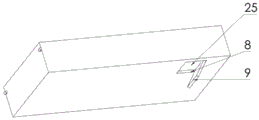
the box body is divided into an upper recoverable garbage collection layer 2 and a lower kitchen garbage collection layer 3 which are arranged at the upper layer and the lower layer through a carriage partition plate 8; be equipped with upper garbage entry 1 on the box top cap, be equipped with lower floor's rubbish entry 25 on the carriage baffle 8, upper garbage entry 1, lower floor's rubbish entry 25 are articulated on the same vertical direction, lower floor's rubbish entry 25 has apron 9.
Furthermore, the upper layer garbage inlet 1 and the lower layer garbage inlet 25 are close to the side of the carriage, so that garbage is easy to pour into the carriage.
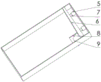
Furthermore, the upper-layer garbage compression mechanism comprises a hydraulic oil cylinder I5, a compression plate I6 and a telescopic rod I7;
the hydraulic oil cylinder I5 is arranged at one end of the upper recyclable garbage collection layer 2, and the hydraulic oil cylinder I5 is connected with the compression plate I6 through the telescopic rod I7;
the upper garbage compression mechanism controls the telescopic motion of the telescopic rod I7 through the hydraulic oil cylinder I5 to control the compression motion of the compression plate I6.
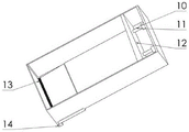
Further, the lower-layer garbage compression mechanism comprises a hydraulic oil cylinder II 10, a telescopic rod II 11 and a compression plate II 12;
the hydraulic oil cylinder II 10 is arranged at one end of the lower kitchen waste collection layer 3, and the hydraulic oil cylinder II 10 is connected with the compression plate II 12 through the telescopic rod II 11;
and the lower-layer garbage compression mechanism controls the telescopic motion of the telescopic rod II 11 through the hydraulic oil cylinder II 10 to control the compression motion of the compression plate II 12.
Further, the compression plate I6 is designed to be wedge-shaped, wherein the thickness of one end of the compression plate I6 close to the lower layer garbage inlet 25 is larger than that of the other end.
Further, the compression plate II 12 is designed to be wedge-shaped, wherein the thickness of one end, close to the lower layer garbage inlet 25, of the compression plate I6 is larger than that of the other end.
Further, the sewage treatment system 4 comprises a filter plate I13, a sewage converging channel 23 and a filter plate II 24; 3 afterbody on lower floor's kitchen garbage collection layer is fixed to filter I13, and sewage conflux passageway 23 is the slope type passageway of a height from left to right, fixes below filter I13, and filter II 24 passes through the screw connection to be fixed at the tail of sewage conflux passageway 23 the right.
Further, the sewage collecting device comprises a sewage baffle 14, a sewage baffle placing mechanism 15, a sewage baffle placing interlayer 16 and a sewage collecting box 17;
the sewage baffle 14 is detachably arranged above the filter plate II 24 through the sewage baffle placing mechanism 15 and is used for preventing sewage from flowing out through the filter plate II 24 when the sewage collecting box 17 is treated so as to cause secondary pollution; meanwhile, a sewage baffle placing interlayer 16 for placing the sewage baffle 14 at ordinary times is arranged on the carriage body, so that the carriage is convenient for workers to operate;
the sewage baffle placing mechanism 15 is arranged on the side wall of the tail part of the sewage converging channel 23 of the sewage treatment system 4, and the sewage baffle placing interlayer 16 is arranged on the side surface of one end of the sewage converging channel 23 of the sewage treatment system 4; the sewage collecting box 17 is arranged at the lower part of a filter plate II 24 of the sewage treatment system 4.
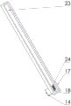
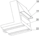
Further, the sewage baffle placing mechanism 15 is L-shaped, and when the sewage baffle placing mechanism is vertical, an upper-layer sewage scraper 18, a lower-layer sewage scraper 20 and a brush 19 are fixed on the back surface of the L-shaped; so that when the sewage baffle 14 is drawn out from the sewage baffle placing mechanism 15, the sewage scraper 18 at the upper layer, the sewage scraper 20 at the lower layer and the brush 19 perform basic cleaning work on the sewage baffle 14, and the sewage is prevented from flowing out along with the drawing-out of the sewage baffle 14 to cause secondary pollution to the environment.
Further, the sewage baffle placing mechanism 15 is a detachable device; when the sewage treatment system is vertical, the sliding block 22 is arranged on the L-shaped bottom surface, and the sliding block 22 is in sliding connection with the sliding groove 26 on the side wall of the tail part of the sewage converging channel 23 of the sewage treatment system 4;
the outer side of the sewage baffle placing mechanism 15 is ensured to keep the position unchanged when the garbage compartment works through the stabilizing frame 21, and the upper-layer sewage scraper 18, the lower-layer sewage scraper 20 and the hairbrush 19 are cleaned or replaced by disassembling the sewage baffle placing mechanism 15;
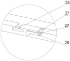
the stabilizer 21 comprises a movable cylinder 27 and a handle 28; the movable cylinder 27 is fixedly connected with the handle 28 and located outside the movable cylinder 27, and a baffle 29 is arranged on the side wall of the tail part of the sewage converging channel 23 and used for preventing the movable cylinder 27 from sliding out under the action of an outward acting force, when the handle 28 is rotated, the movable cylinder 27 is driven to rotate on the side wall of the tail part of the sewage converging channel 23, and the handle 28 is rotated to block the sewage baffle placing mechanism 15 to prevent the sewage baffle placing mechanism from sliding out.
The utility model has the advantages that:
1. the utility model discloses a double-deck categorised garbage truck carriage controls through the compression board to the kitchen garbage layer to the apron that makes baffle department opens and is closed, and then realizes the categorised collection of rubbish.
2. The wedge-shaped compression plates of each layer work, so that the whole compartment space is utilized to the maximum.
3. The sewage collecting system with the double-layer filter plate designed at the tail of the kitchen waste layer improves the solid-liquid separation capacity and is provided with a sewage baffle, so that when a sewage discharge point is reached and a sewage collecting box is manually dumped, sewage leakage is prevented, and secondary pollution is caused to the environment. The whole process is simple to operate and high in practicability.
Drawings
Fig. 1 is a schematic view of the external structure of the car body of the present invention;
FIG. 2 is a schematic view of the recyclable garbage layer of the present invention 1;
FIG. 3 is a schematic view of the recyclable garbage layer of the present invention shown in FIG. 2;
FIG. 4 is a schematic view of the structure of the kitchen waste collection layer of the present invention;
FIG. 5 is a schematic view of the sewage treatment system of the present invention;
FIG. 6 is a schematic view of the sewage collecting device of the present invention;
FIG. 7 is a schematic structural view of a sewage baffle placing mechanism in the sewage collecting device of the present invention;
FIG. 8 is a schematic view of a part of the structure of the stabilizer and the sewage baffle placement mechanism of the present invention;
FIG. 9 is a schematic view of the structure of the stabilizer, the baffle and the chute of the present invention;
FIG. 10 is a schematic view of the stabilizer of the present invention;
fig. 11 is a schematic diagram of a simple structure in application of the present invention.
The various reference numbers in FIGS. 1-11: 1-upper layer garbage inlet, 2-upper layer recoverable garbage collection layer, 3-lower layer kitchen garbage collection layer, 4-sewage treatment system, 5-hydraulic oil cylinder I, 6-compression plate I, 7-telescopic rod I, 8-carriage partition plate, 9-cover plate, 10-hydraulic oil cylinder II, 11-telescopic rod II, 12-compression plate II, 13-filter plate I, 14-sewage baffle, 15-sewage baffle placing mechanism, 16-sewage baffle placing interlayer, 17-sewage collection box, 18-upper layer sewage scraper, 19-hairbrush, 20-lower layer sewage scraper, 21-stabilizing frame, 22-slide block, 23-sewage converging channel, 24-filter plate II, 25-lower layer garbage inlet and 26-chute, 27-movable cylinder, 28-handle, 29-baffle.
Detailed Description
The present invention will be further described with reference to the accompanying drawings and specific embodiments.
Example 1: as shown in fig. 1-11, a double-layer classification garbage truck carriage comprises a box body, an upper layer garbage compression mechanism, a lower layer garbage compression mechanism, a sewage treatment system 4 and a sewage collection device;
the box body is divided into an upper recoverable garbage collection layer 2 and a lower kitchen garbage collection layer 3 which are arranged at the upper layer and the lower layer through a carriage partition plate 8; be equipped with upper garbage entry 1 on the box top cap, be equipped with lower floor's rubbish entry 25 on the carriage baffle 8, upper garbage entry 1, lower floor's rubbish entry 25 are articulated on the same vertical direction, lower floor's rubbish entry 25 has apron 9.
Furthermore, the upper layer garbage inlet 1 and the lower layer garbage inlet 25 are close to the side of the carriage, so that garbage is easy to pour into the carriage.
Furthermore, the upper-layer garbage compression mechanism comprises a hydraulic oil cylinder I5, a compression plate I6 and a telescopic rod I7;
the hydraulic oil cylinder I5 is arranged at one end of the upper recyclable garbage collection layer 2, and the hydraulic oil cylinder I5 is connected with the compression plate I6 through the telescopic rod I7;
the upper garbage compression mechanism controls the telescopic motion of the telescopic rod I7 through the hydraulic oil cylinder I5 to control the compression motion of the compression plate I6.
Further, the lower-layer garbage compression mechanism comprises a hydraulic oil cylinder II 10, a telescopic rod II 11 and a compression plate II 12;
the hydraulic oil cylinder II 10 is arranged at one end of the lower kitchen waste collection layer 3, and the hydraulic oil cylinder II 10 is connected with the compression plate II 12 through the telescopic rod II 11;
and the lower-layer garbage compression mechanism controls the telescopic motion of the telescopic rod II 11 through the hydraulic oil cylinder II 10 to control the compression motion of the compression plate II 12.
Further, the compression plate I6 is designed to be wedge-shaped, wherein the thickness of one end of the compression plate I6 close to the lower layer garbage inlet 25 is larger than that of the other end.
Further, the compression plate II 12 is designed to be wedge-shaped, wherein the thickness of one end, close to the lower layer garbage inlet 25, of the compression plate I6 is larger than that of the other end.
Further, the sewage treatment system 4 comprises a filter plate I13, a sewage converging channel 23 and a filter plate II 24; 3 afterbody on lower floor's kitchen garbage collection layer is fixed to filter I13, and sewage conflux passageway 23 is the slope type passageway of a height from left to right, fixes below filter I13, and filter II 24 passes through the screw connection to be fixed at the tail of sewage conflux passageway 23 the right.
Further, the sewage collecting device comprises a sewage baffle 14, a sewage baffle placing mechanism 15, a sewage baffle placing interlayer 16 and a sewage collecting box 17;
the sewage baffle 14 is detachably arranged above the filter plate II 24 through the sewage baffle placing mechanism 15 and is used for preventing sewage from flowing out through the filter plate II 24 when the sewage collecting box 17 is treated so as to cause secondary pollution; meanwhile, a sewage baffle placing interlayer 16 for placing the sewage baffle 14 at ordinary times is arranged on the carriage body, so that the carriage is convenient for workers to operate;
the sewage baffle placing mechanism 15 is arranged on the side wall of the tail part of the sewage converging channel 23 of the sewage treatment system 4, and the sewage baffle placing interlayer 16 is arranged on the side surface of one end of the sewage converging channel 23 of the sewage treatment system 4; the sewage collecting box 17 is arranged at the lower part of a filter plate II 24 of the sewage treatment system 4.
Further, the sewage baffle placing mechanism 15 is L-shaped, and when the sewage baffle placing mechanism is vertical, an upper-layer sewage scraper 18, a lower-layer sewage scraper 20 and a brush 19 are fixed on the back surface of the L-shaped; so that when the sewage baffle 14 is drawn out from the sewage baffle placing mechanism 15, the sewage scraper 18 at the upper layer, the sewage scraper 20 at the lower layer and the brush 19 perform basic cleaning work on the sewage baffle 14, and the sewage is prevented from flowing out along with the drawing-out of the sewage baffle 14 to cause secondary pollution to the environment.
Further, the sewage baffle placing mechanism 15 is a detachable device; when the sewage treatment system is vertical, the sliding block 22 is arranged on the L-shaped bottom surface, and the sliding block 22 is in sliding connection with the sliding groove 26 on the side wall of the tail part of the sewage converging channel 23 of the sewage treatment system 4;
the outer side of the sewage baffle placing mechanism 15 is ensured to keep the position unchanged when the garbage compartment works through the stabilizing frame 21, and the upper-layer sewage scraper 18, the lower-layer sewage scraper 20 and the hairbrush 19 are cleaned or replaced by disassembling the sewage baffle placing mechanism 15;
the stabilizer 21 comprises a movable cylinder 27 and a handle 28; the movable cylinder 27 is fixedly connected with the handle 28 and located outside the movable cylinder 27, and a baffle 29 is arranged on the side wall of the tail part of the sewage converging channel 23 and used for preventing the movable cylinder 27 from sliding out under the action of an outward acting force, when the handle 28 is rotated, the movable cylinder 27 is driven to rotate on the side wall of the tail part of the sewage converging channel 23, and the handle 28 is rotated to block the sewage baffle placing mechanism 15 to prevent the sewage baffle placing mechanism from sliding out.
The utility model discloses a working process is:
the whole box body is divided into an upper layer and a lower layer through a compartment partition plate 8, the upper layer collects recoverable garbage (plastic, paper and the like), and the lower layer collects kitchen garbage (sewage containing vegetable juice);
when the garbage recycling vehicle is used for recycling garbage, kitchen garbage is poured into the carriage box body from the upper garbage inlet 1, at the moment, the kitchen garbage enters the lower kitchen garbage collection layer 3 because the cover plate 9 at the position of the carriage partition plate 8 is in a natural falling state, the hydraulic oil cylinder II 10 works, the telescopic motion of the telescopic rod II 11 is controlled through the hydraulic oil cylinder II 10 to control the compression motion of the compression plate II 12 (the garbage compression ratio is improved), and the kitchen garbage is pushed to the tail part of the carriage; at this moment, the cover plate 9 is pushed to be flat due to the operation of the compression plate II 12, so that the lower-layer kitchen waste carriage is in a sealing state, at this moment, the compression plate II 12 is pushed to the lower side of the cover plate 9 to enable the cover plate 9 to be stable and immobile, the maximum length of the extension rod II 11 is formed when the compression plate II 12 is pushed to the lower side of the cover plate 9, and when the compression plate II 12 is pushed, garbage collected at the back sequentially pushes the garbage of the previous wave to move towards the tail of the carriage.
At the moment, recoverable rubbish is poured into the compartment body from the upper-layer rubbish inlet 1, the cover plate 9 is closed at the moment, recoverable rubbish is poured into the upper-layer recoverable rubbish collection layer 2 naturally, the compression plate I6 runs, the telescopic motion of the telescopic rod I7 is controlled through the hydraulic oil cylinder I5, the compression motion of the compression plate I6 is pushed to the tail portion of the compartment, the compression plate I6 returns to the original position, the compression plate II 12 also starts to move at the moment and returns to the original position, the cover plate 9 returns to the natural falling state along with the movement of the compression plate II 12, and one-time movement is completed.
When the rubbish volume of retrieving is enough many times to rubbish is under the compression effect of compression board, and 3 inevitable sewage that have in lower floor's kitchen garbage collection layer are in the railway carriage or compartment body to rubbish, because the railway carriage or compartment body design is for having an inclination, make sewage can flow to the carriage afterbody, the utility model discloses the double-deck categorised garbage truck railway carriage or compartment body is equipped with filter I13 at the afterbody, makes large-scale solid and sewage separation, and the sewage that is mingled with the small-size granule gets into sewage and converges passageway 23 through the filtration pore, flows into the position of filter II 24, and the hole of filter II 24 is far less than the hole of filter I13 for small-size granule and sewage separation, sewage pass through filtration pore entering sewage collecting box.
After the garbage recycling truck finishes one-time work, the garbage recycling truck arrives at a garbage disposal plant, and the recyclable garbage and the kitchen garbage are respectively discharged from the tail outlet (the tail outlet is an openable movable hinged door) of each layer of carriage through the garbage truck self-discharging device. The sewage collection tank 17 will dispose of the sewage by manual operation. At this moment, the worker firstly puts the sewage baffle 14, place the intermediate layer 16 from the sewage baffle and go out and take out, insert from sewage baffle placement mechanism 15, make sewage temporarily kept off at sewage confluence passageway 23, change sewage collecting box 17 again, sewage just can not leak when changing the collecting box like this, cause secondary pollution to the environment, sewage collecting box 17 is changed and is accomplished the back, the worker takes out sewage baffle 14, sewage baffle 14 is under the preliminary cleaning action of upper sewage scraper blade 18, brush 19, lower floor's sewage scraper blade 20, can not have sewage when taking out, thereby can not cause secondary pollution to the environment yet.
Because the design is being close to the position of avris for the convenience of collection in upper garbage entry 1 and lower floor's rubbish entry 25 that design, if can cause the dustbin opposite side space to utilize inadequately when designing for straight compression board compression then, the compression board design is the wedge, can make rubbish at compression board propulsion in-process, from upper garbage entry 1 and lower floor's rubbish entry 25 fall recoverable rubbish collection layer 2, the rubbish on 3 avris in kitchen garbage collection layer is easily pushed to the opposite side, space utilization is improved.
Hinged cover plates 9 are arranged at the garbage inlets 25 on the upper layer and the lower layer of the compartment partition plate 8, and the layer position of garbage entering the box body is controlled through the cover plates 9. For example, the cover plate 9 is in a natural falling state at ordinary times, and the garbage can directly reach the lower kitchen garbage collection layer 3 after entering the box. The compression plate II 12 works to push the garbage to one side of the tail part of the box body, and meanwhile, the cover plate 9 can be lifted under the action of the movement of the compression plate II 12, so that the lower-layer garbage inlet 25 is closed. Recoverable rubbish is poured into this moment, and rubbish only can reach recoverable rubbish collection layer 2 in upper strata, and then accomplishes rubbish classification and collects, the utility model discloses can use on the garbage truck, as the carriage of garbage truck, simple application schematic diagram is shown in figure 11.
While the present invention has been particularly shown and described with reference to the preferred embodiments, it will be understood by those skilled in the art that various changes in form and details may be made therein without departing from the spirit and scope of the invention.
Claims (10)
1. The utility model provides a double-deck categorised garbage truck carriage which characterized in that: comprises a box body, an upper layer garbage compression mechanism, a lower layer garbage compression mechanism, a sewage treatment system (4) and a sewage collection device;
the box body is divided into an upper recoverable garbage collection layer (2) and a lower kitchen garbage collection layer (3) through a carriage partition plate (8); the upper layer garbage inlet (1) is arranged on the top cover of the box body, the lower layer garbage inlet (25) is arranged on the compartment partition plate (8), the upper layer garbage inlet (1) and the lower layer garbage inlet (25) are arranged in the same vertical direction, and the lower layer garbage inlet (25) is hinged with the cover plate (9).
2. The double-deck classification garbage truck carriage as claimed in claim 1, characterized in that: the upper layer garbage inlet (1) and the lower layer garbage inlet (25) are close to the side of the carriage, and garbage is easily poured into the carriage.
3. The double-deck classification garbage truck carriage as claimed in claim 1, characterized in that:
the upper-layer garbage compression mechanism comprises a hydraulic oil cylinder I (5), a compression plate I (6) and a telescopic rod I (7);
the hydraulic oil cylinder I (5) is arranged at one end of the upper recoverable garbage collection layer (2), and the hydraulic oil cylinder I (5) is connected with the compression plate I (6) through a telescopic rod I (7);
the upper-layer garbage compression mechanism controls the telescopic motion of the telescopic rod I (7) through the hydraulic oil cylinder I (5) to control the compression motion of the compression plate I (6).
4. The double-deck classification garbage truck carriage as claimed in claim 1, characterized in that:
the lower-layer garbage compression mechanism comprises a hydraulic oil cylinder II (10), a telescopic rod II (11) and a compression plate II (12);
the hydraulic oil cylinder II (10) is arranged at one end of the lower kitchen waste collection layer (3), and the hydraulic oil cylinder II (10) is connected with the compression plate II (12) through the telescopic rod II (11);
and the lower-layer garbage compression mechanism controls the telescopic motion of the telescopic rod II (11) through the hydraulic oil cylinder II (10) to control the compression motion of the compression plate II (12).
5. The double-deck classification garbage truck carriage as claimed in claim 3, characterized in that: the compression plate I (6) is designed into a wedge shape, wherein the thickness of one end, close to the lower-layer garbage inlet (25), of the compression plate I (6) is larger than that of the other end of the compression plate I.
6. The double-deck classification garbage truck carriage as claimed in claim 4, characterized in that: the compression plate II (12) is designed to be wedge-shaped, wherein the thickness of one end, close to the lower-layer garbage inlet (25), of the compression plate II (12) is larger than that of the other end of the compression plate II.
7. The double-deck classification garbage truck carriage as claimed in claim 1, characterized in that:
the sewage treatment system (4) comprises a filter plate I (13), a sewage converging channel (23) and a filter plate II (24); filter I (13) are fixed in lower floor kitchen garbage collection layer (3) afterbody, and sewage converges passageway (23) and is the slope type passageway of a height from left to right low, fixes below filter I (13), and filter II (24) are fixed at sewage passageway (23) afterbody on the right through the screw connection.
8. The double-deck classification garbage truck carriage as claimed in claim 1, characterized in that:
the sewage collecting device comprises a sewage baffle (14), a sewage baffle placing mechanism (15), a sewage baffle placing interlayer (16) and a sewage collecting box (17);
the sewage baffle (14) is detachably arranged above the filter plate II (24) through the sewage baffle placing mechanism (15) and is used for preventing sewage from flowing out through the filter plate II (24) when the sewage collecting box (17) is treated to cause secondary pollution; meanwhile, a sewage baffle plate placing interlayer (16) for placing the sewage baffle plate (14) at ordinary times is arranged on the carriage body, so that the carriage is convenient for workers to operate;
the sewage baffle placing mechanism (15) is arranged on the side wall of the tail part of the sewage converging channel (23) of the sewage treatment system (4), and the sewage baffle placing interlayer (16) is arranged on the side surface of one end of the sewage converging channel (23) of the sewage treatment system (4); the sewage collecting box (17) is arranged at the lower part of a filter plate II (24) of the sewage treatment system (4).
9. The double-deck classification garbage truck carriage of claim 8, characterized in that:
the sewage baffle placing mechanism (15) is L-shaped, and when the sewage baffle placing mechanism is vertical, an upper-layer sewage scraper (18), a lower-layer sewage scraper (20) and a brush (19) are fixed on the back surface of the L-shaped; when the sewage baffle plate (14) is drawn out from the sewage baffle plate placing mechanism (15), the upper layer sewage scraper blade (18), the lower layer sewage scraper blade (20) and the brush (19) perform basic cleaning work on the sewage baffle plate (14), and the sewage is prevented from flowing out along with the drawing-out of the sewage baffle plate (14) to cause secondary pollution to the environment.
10. The double-deck classification garbage truck carriage as claimed in claim 9, characterized in that:
the sewage baffle placing mechanism (15) is a detachable device; when the device is vertical, a sliding block (22) is arranged on the L-shaped bottom surface, and the sliding block (22) is in sliding connection with a sliding groove (26) on the side wall of the tail part of a sewage converging channel (23) of the sewage treatment system (4);
the outer side of the sewage baffle placing mechanism (15) ensures that the position of the garbage compartment is kept unchanged when the garbage compartment works through a stabilizing frame (21), and the upper-layer sewage scraper blade (18), the lower-layer sewage scraper blade (20) and the brush (19) are cleaned or replaced by disassembling the sewage baffle placing mechanism (15);
the stabilizing frame (21) comprises a movable cylinder (27) and a handle (28); the movable cylinder (27) is fixedly connected with the handle (28); the baffle plate (29) is arranged on the side wall of the tail of the sewage converging channel (23) and used for preventing the movable cylinder (27) from sliding out under the action of an outward acting force, when the handle (28) is rotated, the movable cylinder (27) is driven to rotate on the side wall of the tail of the sewage converging channel (23), and the handle (28) is rotated to block the sewage baffle plate placing mechanism (15) to prevent the sewage baffle plate placing mechanism from sliding out.
Priority Applications (1)
| Application Number | Priority Date | Filing Date | Title |
|---|---|---|---|
| CN201822010154.5U CN210028773U (en) | 2018-12-03 | 2018-12-03 | Double-layer classification garbage truck carriage |
Applications Claiming Priority (1)
| Application Number | Priority Date | Filing Date | Title |
|---|---|---|---|
| CN201822010154.5U CN210028773U (en) | 2018-12-03 | 2018-12-03 | Double-layer classification garbage truck carriage |
Publications (1)
| Publication Number | Publication Date |
|---|---|
| CN210028773U true CN210028773U (en) | 2020-02-07 |
Family
ID=69342670
Family Applications (1)
| Application Number | Title | Priority Date | Filing Date |
|---|---|---|---|
| CN201822010154.5U Expired - Fee Related CN210028773U (en) | 2018-12-03 | 2018-12-03 | Double-layer classification garbage truck carriage |
Country Status (1)
| Country | Link |
|---|---|
| CN (1) | CN210028773U (en) |
Cited By (2)
| Publication number | Priority date | Publication date | Assignee | Title |
|---|---|---|---|---|
| CN109573417A (en) * | 2018-12-03 | 2019-04-05 | 昆明理工大学 | A kind of classifying refuse vehicle compartment with sewage treatment function |
| CN111532633A (en) * | 2020-05-08 | 2020-08-14 | 孙茂峰 | Garbage compression device of garbage truck |
-
2018
- 2018-12-03 CN CN201822010154.5U patent/CN210028773U/en not_active Expired - Fee Related
Cited By (2)
| Publication number | Priority date | Publication date | Assignee | Title |
|---|---|---|---|---|
| CN109573417A (en) * | 2018-12-03 | 2019-04-05 | 昆明理工大学 | A kind of classifying refuse vehicle compartment with sewage treatment function |
| CN111532633A (en) * | 2020-05-08 | 2020-08-14 | 孙茂峰 | Garbage compression device of garbage truck |
Similar Documents
| Publication | Publication Date | Title |
|---|---|---|
| CN109573417B (en) | Classification garbage truck carriage with sewage treatment function | |
| CN205076336U (en) | Categorised compression garbage truck | |
| CN210028773U (en) | Double-layer classification garbage truck carriage | |
| CN214320380U (en) | Garbage disposal device | |
| CN113148474A (en) | Energy-saving and environment-friendly kitchen garbage classification equipment | |
| CN211935779U (en) | Sewage solid waste collection device | |
| CN112108491A (en) | Environment-friendly refuse handling installation | |
| CN207242613U (en) | A kind of kitchen garbage collector | |
| CN103144343B (en) | Vertical quantitative pre-compaction large trash compactor | |
| CN210012676U (en) | Kitchen waste oil purification treatment device | |
| CN215884935U (en) | A device for rubbish solid-liquid separation | |
| CN214688083U (en) | Garbage leachate collector | |
| CN214289945U (en) | Environment-friendly refuse handling installation | |
| CN210100784U (en) | Efficient domestic waste treatment equipment | |
| CN204568568U (en) | Improved type cram packer | |
| CN210280158U (en) | Kitchen waste regenerating device | |
| CN105668072B (en) | A kind of minitype waste processing equipment | |
| CN208261518U (en) | A kind of environment-friendly type solid waste processing unit | |
| CN111347704A (en) | Efficient domestic waste treatment equipment | |
| CN105540117A (en) | Extrusion type environmental sanitation processing vehicle | |
| CN213651939U (en) | Hand propelled meal kitchen oil water separator | |
| CN210883650U (en) | Passenger compartment solid-liquid garbage classification box | |
| CN210208064U (en) | Kitchen waste treatment system | |
| CN204368831U (en) | A kind of garbage truck box body back door with filtering and draining device | |
| CN219567640U (en) | Kitchen waste sewage treatment device |
Legal Events
| Date | Code | Title | Description |
|---|---|---|---|
| GR01 | Patent grant | ||
| GR01 | Patent grant | ||
| CF01 | Termination of patent right due to non-payment of annual fee | ||
| CF01 | Termination of patent right due to non-payment of annual fee |
Granted publication date: 20200207 Termination date: 20201203 |